DD4UT2DFace Held Wireless Microphone
Shure Incorporated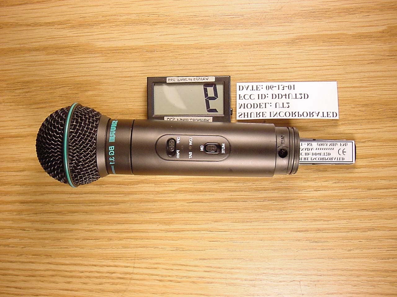
Click to zoom
Application Details
- Equipment Class
- TNF - Licensed Non-Broadcast Transmitter Held to Face
- Date of Grant
- Jul 25, 2001
- Application Purpose
- Original Equipment
- Date of Application
- Jul 25, 2001
- Equipment Note
- Face Held Wireless Microphone
- Frequency Range
- 560.00000000 - 599.00000000
- Company
- Shure Incorporated
- Country
- United States
Documents & Files
Document Text
Text extracted from the exhibit documents filed with the FCC. Open a document above to read the original.
Users Manual
ENGLISH THE TWO MINUTE USER’S GUIDE 2:00 The instructions on this page will help you get your UT Series system up and running in minutes. For more detailed instructions, read the section of this manual that applies to your system. RECEIVER SETUP 1. Connect the supplied ac power adapter to the DC INPUT connector on the back of the receiver. Insert the adapter’s cable into the power cable retainer on the bottom of the unit. Plug the adapter into a wall socket or other electrical outlet. The green POWER light on the receiver will glow. 2. If you are using The Guitarist-UHF, connect the receiver output to a guitar am- plifier using any standard guitar cable. If you are using The Vocal Artist-UHF, The Headset-UHF, or The Presenter-UHF, connect the receiver output to an audio mixer using an XLR to XLR audio cable. 3. Raise the antennas and point away from each other at a 45° angle from vertical. TRANSMITTER SETUP 1. Open the transmitter battery compartment and install a 9 V battery. Observe proper battery polarity (“+/–”). 2. If you are using The Vocal Artist-UHF, no further transmitter setup is required. 3. If you are using a body-pack transmitter (The Presenter-UHF, The Headset-UHF or The Guitarist-UHF), plug the microphone cable or a WA302 instrument cable into the four-pin connector on the transmitter (if using The Headset-UHF, see tag on headset for assembly instructions). If using The Guitarist-UHF, plug the instru- ment cable into the guitar output and adjust the volume control of the guitar. OPERATING THE SYSTEM 1. Slide the transmitter POWER/OFF switch to the POWER position. The transmitter’s green POWER light and the receiver’s yellow DIVERSITY A/B lights will glow. 2. Slide the MUTE/ON switch on the body-pack or hand-held transmitter to the ON position. 3. Talk or sing into the microphone, or play your guitar. The receiver’s red AUDIO PEAK light should flicker when loud sounds are transmitted. If the AUDIO PEAK light does not flicker or stays on constantly, the transmitter gain may need adjustment. (Refer to the Transmitter Audio Gain Adjustment section). NOTE: This step is particularly important for The Guitarist system, since guitar outputs can vary widely. 4. Adjust the receiver VOLUME control until the receiver output level matches the level of your guitar or microphone through a cable. (The factory setting is in the full clockwise position.) If using The Guitarist-UHF system, see Receiver Volume Adjustment for The Guitarist-UHF to match the receiver volume level to the level of a wired system. YOU ARE NOW READY TO PERFORM! IMPORTANT: Every wireless performance is a unique situation, and can present a vari- ety of problems. Never attempt a performance without first conducting a “walkthrough” test on the wireless system in the performing area. If you encounter a problem, refer to the Troubleshooting table. 2 ENGLISH THANK YOU FOR CHOOSING SHURE Congratulations! You have purchased the finest wireless system in its class. Your Shure wireless system is engineered to provide a low-noise, high-quality sound comparable to other systems costing much more. Built in the tradition of reliability that has made Shure a symbol of American quali- ty for more than half a century, this wireless system should provide you with excellent performance for years. To get the most out of your UT Series wireless system, please read the applicable section in this guide before you attempt to use the system. If you have any questions that are not answered in this booklet, please contact Shure Customer Service at (847) 866-2553, Monday through Friday, from 8:00 am to 4:30 pm, Central Standard Time. For technical data by fax, dial (800)488-3297 and follow the recorded instructions. Visit our website at www.shure.com for further information on this and other Shure products. INTRODUCTION Your new UT Series system is designed to give you the best of both sound reinforce- ment worlds: the freedom of a wireless system, and the reliability of world-famous Shure sound quality. This manual covers each of the UT Series systems: The Vocal Artist-UHF, The Presenter-UHF, The Headset-UHF, and The Guitarist-UHF. SYSTEM FEATURES All Shure UT Series systems offer a variety of of exceptional features, including: •Diversity Receivers with Exclusive Shure MARCAD Circuitry: MARCAD (MAximum Ratio Combining Audio Diversity) circuitry continuously processes the rf signal from each antenna and combines the audio outputs to produce one signal of optimum quality. The result is improved reception and exceptional free- dom from dropouts. •Low-Traffic UHF Transmission: UT systems use a UHF (Ultra High Frequen- cy) range between approximately 596 to 862 MHz (available frequencies de- pend on regulations in the country where the system is used). In urban areas, UHF frequencies are less congested than those in the VHF range, and are less susceptible to interference. •Multiple System Use: Up to eight UT systems can be used in the same perfor- mance space. Each system must be set at a different frequency. If systems are set to the same frequency, contact an authorized Shure dealer. NOTE: In multi- ple use situations, each transmitter must have a dedicated receiver. •Simultaneous Output Use: Unbalanced 1 / 4 ” phone plug and balanced XLR output connectors may be used simultaneously to different external devices. •Stackable and Rack-Mountable Receivers: If multiple systems are in use, re- ceivers may either be stacked or rack-mounted, with two receivers fitting in the optional rack mount tray. In these situations, antennas should not touch or be crossed. (See Stacking and Rack-mounting Receivers.) •Range: UT Series transmitters will work at a distance of up to 100 meters (about 300 ft.) from the receiver. •Noise Squelch: The noise squelch circuit analyzes signal quality instead of sig- nal strength, which allows the circuit to discriminate between noise and desired signal. This reduces the likelihood of noise burst due to environmental rf (…
Text truncated - open the document above for the full version.
Cover Letter(s)
Letter of Agency Date: July 18, 2001 American Telecommunications Certification Body, Inc. 6731 Whittier Avenue Suite C110 McLean, VA 22101 To Whom It May Concern: Please be advised that Shure, Inc. authorizes D.L.S. Electronic Systems, Inc. to act on our behalf, until otherwise notified, for applications submitted to American Telecommunications Certification Body, Inc. (ATCB). We certify that we are not subject to denial of federal benefits, that includes FCC benefits, pursuant to Section 5301 of the Anti-Drug Abuse ACT of 1988, U.S.C. 862. Further, no party, as defined in 47 CFR 1.2002(b), to the application is subject to denial of federal benefits, that includes FCC benefits. Thank you for your attention to this matter. Signatory, Arnom C. Rowe EMC ENGINEER EMC-001375-NE D.L.S. Electronic Systems, Inc. FCC Labeling Requirements and Information Date: July 18,2001 American Telecommunications Certification Body, Inc. 6731 Whittier Avenue Suite C110 McLean, VA 22101 RE: FCC Labeling Requirements FCC ID:DD4 UT2D The following label information is required by the FCC Rules and Regulations for certified devices. Also attached, please find marketing information required by the FCC Rules and Regulations. Thank you for your attention to these matters. Sincerely, Arnom C. Rowe EMC ENGINEER EMC-001375-NE D.L.S. Electronic Systems, Inc. Request for Confidentiality Date: July 18,2001 American Telecommunications Certification Body, Inc. 6731 Whittier Avenue Suite C110 McLean, VA 22101 RE: Certification Application FCC ID: DD4UT2D Please be advised that the following information is to be held confidential and behalf of APPLICANT NAME: • Operational Description • Block Diagram • Schematics • Parts Lists • Internal Photos The application contains technical information which Shure, Inc. deems to be trade secrets and proprietary. If made public, the information might be used to the disadvantage of the applicant in the market place. Thank you for your attention to this matter. Signatory Arnom C. Rowe EMC ENGINEER EMC-001375-NE D.L.S. Electronic Systems, Inc. Modification Letter Date: July 18,2001 American Telecommunications Certification Body, Inc. 6731 Whittier Avenue847-537-6488 Suite C110 McLean, VA 22101 RE: Certification Application FCC ID:DD4 UT2D Please be advised that the following information is a list of modifications that will be included in the production process for the above-referenced equipment. Change 1: There were no modifications made during testing. Change 2: Change 3: Change 4: Change 5: Change 6: Change 7: Change 8: Change 9 Change 10: Thank you for your attention to this matter. Signatory Arnom C. Rowe EMC ENGINEER EMC-001375-NE D.L.S. Electronic Systems, Inc. Manufacturer’s Letter Date: July 18,2001 American Telecommunications Certification Body, Inc. 6731 Whittier Avenue Suite C110 McLean, VA 22101 RE: Certification Application FCC ID: DD4UT2D To Whom It May Concern: Please be advised that the manufacturer will ensure that the above-referenced model will be manufactured in accordance with the FCC Rules and Regulations. Thank you for your attention to this matter. Signatory Arnom C. Rowe EMC ENGINEER EMC-001375-NE D.L.S. Electronic Systems, Inc.
Cover Letter(s)
American Telecommunications Certification Body Inc. 6731 Whittier Ave, McLean, VA 22101 July 19, 2001 RE: Sure Incorporated UT2D FCC ID: DD4UT2D I should have saved myself sometime and looked at both DD4UT1D and DD4UT1D reports together. Essentially my same questions apply from one to the other. 1.) Please confirm if the power output specified in Section 6.0 is Conducted or ERP. If ERP the substitution method generally described in TIA/EIA 603 should be used as opposed to a field strength measurement that is then converted to radiated power. 2.) No graphs were presented of RF Power Output – only a blank page exists on pp. 9. Is this what you intended? 3.) Section 7.0 – FYI: it would be helpful if a deviation value was given at 5000 Hz from an acoustic field of 120dB SPL to show compliance with the Part 74 and 90 limits. 4.) Section 8.0 Occupied Bandwidth – no plots were presented, only blank pages pp. 14 to 23. Even if no direct connection can be made, loose coupling plots to a spectrum analyzer are desirable. Be sure to show unmodulated, 2500 Hz, and 15 KHz cases. Please specify the audio input level used. 5.) Field strength of Spurious Emissions must only be shown using the substitution method of TIA/EIA 603. The Commission has decided that for licensed services, conversion of field strength to ERP is not acceptable. Values more than 20dB below the limit can be ignored. For any further questions on this subject I direct you to Frank Coperich of the Office of Engineering and Technology. 6.) FYI: It is not necessary to present multiple spectrum plots of Frequency vs. Temperature and frequency vs. Voltage – a short data sheet would be very satisfactory. Any questions please don’t hesitate to call or email me direct. Bill William H. Graff Examining Engineer President and Director of Engineering mailto:[email protected] The items indicated above must be submitted before processing can continue on the above referenced application. Failure to provide the requested information may result in application termination. Correspondence should be considered part of the permanent submission and may be viewed from the Internet after a Grant of Equipment Authorization is issued. Please do not respond to this correspondence using the email reply button. In order for your response to be processed expeditiously, you must submit your documents through the AmericanTCB.com website. Also, please note that partial responses increase processing time and should not be submitted. Any questions about the content of this correspondence should be directed to the sender.
External Photos
Front of EUT Bottom of EUT Top Cover removed Microphone removed Battery Cover removed Battery removed
ID Label/Location Info
FCC ID Label
Internal Photos
Circuit Boards removed Audio Board Component Side Audio Board Solder Side RF Board Component Side Audio Board Component Side Interconnect Board Side 1 Interconnect Board Side 2
Test Report
EMC Test Services Report No. 9098 1250 Peterson Drive, Wheeling, Illinois 60090, USA TEST SPECIFICATION: FCC "Rules and Regulations", Part 74, Experimental Radio, Auxiliary, Special Broadcast and Other Program Distribution Services for Operation in the 494 to 608 MHz Band Subpart H, Low Power Auxiliary Stations Sections 74.801 to 74.882 THE FOLLOWING MEETS THE ABOVE TEST SPECIFICATION Formal Name: Shure Incorporated UT2D Wireless Microphone Kind of Equipment: Low Power Transmitter Test Configuration: Continuously Transmitting (Tested at 9 vdc) Emission Designator: 120KF3E Transmitter FCC ID: DD4UT2D Model Number: UT2D Serial Number: NA Dates of Test: June 13, 2001 Test Conducted For: Shure Incorporated 222 Hartrey Avenue Evanston, Illinois 60025-3696 NOTICE: Please see change information listed inside of this report. This report must not be used by the customer to claim product endorsement by NVLAP or any agency of the United States Government, and it cannot be reproduced (except in full), without the approval of D.L.S. Electronic Systems Inc. Page 1 EMC Test Services Report No. 9098 1250 Peterson Drive, Wheeling, Illinois 60090, USA SIGNATURE PAGE Report Written By: Arnom C. Rowe Test Engineer EMC-001375-NE Report Reviewed by: Jack Prawica Lab Manager Report Approved by: Brian J. Mattson General Manager Company Official: Shure Incorporated Page 2 EMC Test Services Report No. 9098 1250 Peterson Drive, Wheeling, Illinois 60090, USA NVLAP Certificate of Accreditation available upon request. Page 3 EMC Test Services Report No. 9098 1250 Peterson Drive, Wheeling, Illinois 60090, USA NVLAP Scope of Accreditation available upon request. Page 4 EMC Test Services Report No. 9098 1250 Peterson Drive, Wheeling, Illinois 60090, USA TABLE OF CONTENTS i. Cover Page.......................................................................................................................................1 ii. Signature Page..................................................................................................................................2 iii NVLAP Certificate of Accreditation available upon request of Contents........................................3 iv NVLAP Scope Certificate of Accreditation available upon request of Contents.............................4 v. Table of Contents..............................................................................................................................5 1.0 Summary of Test Report...................................................................................................................6 2.0 Introduction.......................................................................................................................................6 3.0 Object................................................................................................................................................6 4.0 Test Set-Up.......................................................................................................................................6 5.0 Test Equipment (Bandwidths and Detector Function)......................................................................7 6.0 RF Power Output – Part 2.1046........................................................................................................7 6.0 Graphs Taken of the RF Power.........................................................................................................8 7.0 Modulation Characteristics.............................................................................................................10 7.0 Graphs Taken Showing the Frequency Response of the Audio Modulating Circuit......................11 8.0 Occupied Bandwidth – Part 2.1049................................................................................................13 8.0 Graphs taken of the Occupied Bandwidth Part 2.1049...................................................................14 9.0 Frequency Deviation and Tolerance – Part 74.861.........................................................................25 10.0 Spurious Conducted Emission Measurements made at Antenna Terminals Part 2.105.................26 10.0 Spurious Conducted Emission Data taken at the Antenna Terminals Part 2.1051.........................27 10.0 Spurious Conducted Emission Graphs made at the Antenna Terminals Part 2.1051.....................28 11.0 Field Strength of Spurious Emission Measurements Part 2.1053...................................................29 11.0 Radiated Data Taken for Field Strength Spurious Emission Measurements Part 2.1053..............31 12.0 Frequency Stability Part 2.1055a (Temperature)............................................................................48 12.0 Graphs taken for Frequency Stability when varying the temperature Part 2.1055a.......................49 13.0 Graphs taken for Frequency Stability when varying the Primary Supply Part 2.1055d.................58 14.0 Photo Information and Test Set-Up................................................................................................61 15.0 Radiated Photos taken during Testing............................................................................................62 16.0 Change Information........................................................................................................................64 17.0 Results of Tests...............................................................................................................................66 18.0 Conclusion......................................................................................................................................66 18.0 Table 1 Equipment List...................................................................................................................67 Page 5 EMC Test Services Report No. 9098 1250 Peterson Drive, Wheeling, Illinois 60090, USA 1.0 SUMMARY OF TEST REPORT It was found that the Shure Incorporated UT2D Wirele…
Text truncated - open the document above for the full version.
Contact Information
Applicant
Craig Kozokar(EMC Project Engineer)
Technical Contact
D.L.S. Electronic Systems, Inc.Arnom (Arnie) C Rowe
[email protected]847 537 6400
1250 Peterson Drive · Wheeling, Illinois · United States
Test Firm
DLS Electronic Systems, Inc.William Stumpf
Technical Specifications
| # | Rule Parts | Frequency Range | Power Output | Emission | Tolerance |
|---|---|---|---|---|---|
| 1 | 74 | 560 MHz - 599 MHz | 13.00 mW | 120KF3E | 0.0050000000 % |
Other Applications from Shure Incorporated
DD4IMXBP
Dec 24, 2025UC Wall
Equipment Class
NII - Unlicensed National Information Infrastructure TXDD4SLXD3EG57
Jul 25, 2025Plug-on Wireless Transmitter
Equipment Class
DTS - Digital Transmission System
DD4ULXD8G50
Sep 18, 2024Wireless Gooseneck Transmitter
Equipment Class
DWM - Part 15 Wireless Microphone
DD4ULXD8H50
Sep 18, 2024Wireless Gooseneck Transmitter
Equipment Class
DWM - Part 15 Wireless Microphone
DD4ULXD6G50
Sep 08, 2024Wireless Boundary Transmitter
Equipment Class
TLD - Licensed LPAS Device