DFOC01M55AP434Development Tool
Texas Instruments Deutschland GmbH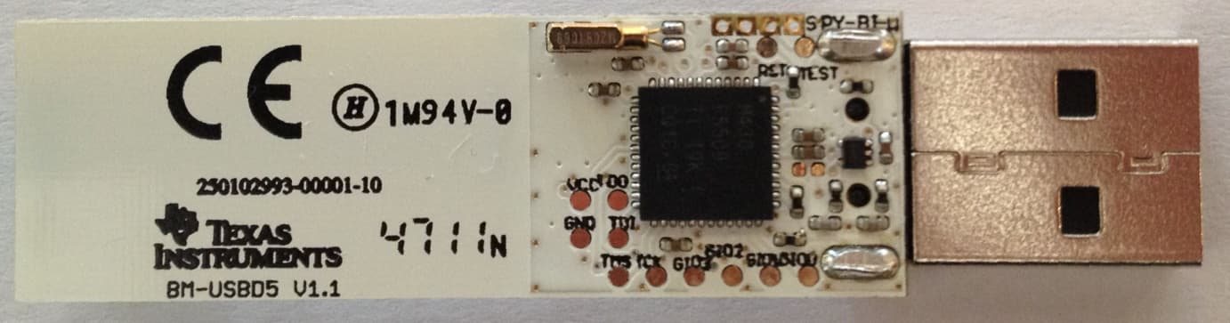
Click to zoom
Application Details
- Equipment Class
- DSC - Part 15 Security/Remote Control Transmitter
- Date of Grant
- Apr 28, 2014
- Application Purpose
- Original Equipment
- Date of Application
- Apr 28, 2014
- Equipment Note
- Development Tool
- Frequency Range
- 433.91000000 - 433.91000000
- Country
- Germany
Documents & Files
Document Text
Text extracted from the exhibit documents filed with the FCC. Open a document above to read the original.
Users Manual
RF430F5978 EVM Kit User’s Guide 2 / 22 11 – November 2013 Contents 3 / 22 11 – November 2013 Table of Contents Page 1 About This User Guide .................................................................................................................................. 6 2 RF430F5978 Demo Kit Overview .................................................................................................................. 6 3 Introduction .................................................................................................................................................... 6 4 Installation ...................................................................................................................................................... 7 4.1 Demo Software Installation EM430F5978 Demo Kit (Attached e2e.ti.com USB Memory Stick) ................ 7 4.2 Hardware Installation of LF-Microreader ..................................................................................................... 7 4.3 Virtual COM Port Driver Installation of LF-Microreader .............................................................................. 7 4.4 UHF Access Point COM Port Driver .........................................................................................................10 5 Start the software .........................................................................................................................................11 6 Using the software .......................................................................................................................................13 7 Schematic .....................................................................................................................................................14 7.1 RF430F5978EVM .....................................................................................................................................14 7.2 APA434R01 ..............................................................................................................................................15 7.3 MRD2EVM ................................................................................................................................................16 8 Revision History ...........................................................................................................................................17 9 IMPORTANT NOTICE ...................................................................................................................................18 Contents 4 / 22 11 – November 2013 Summary of Figures Page No table of figures entries found. RF430F5978 EVM Kit – User Guide 6 / 22 11 – November 2013 1 About This User Guide This manual describes the modules and peripherals of the MCU-RF AES family of devices. Each description presents the module or peripheral in a general sense. Not all features and functions of all modules or peripherals may be present on all devices. In addition, modules or peripherals may differ in their exact implementation between device families, or may not be fully implemented on an individual device or device family. Pin functions, internal signal connections, and operational parameters differ from device to device. The user should consult the device-specific data sheet for these details. The LF communication scheme is described in a dedicated LF user guide. 2 RF430F5978 Demo Kit Overview Install the Demo software and drivers for LF reader and UHF Access Point 3 Introduction The RF430F5978 EVM Software can be used to execute the main features of RF430F5978 device. Resonant trimming, transponder communication (LF Passive Mode) and passive entry (LF Wake Up Mode) communication can be executed. The EVM Software synchronizes its own settings with the device configuration as far as possible to achieve valid data communication and response analyzing. Some devices only offer partial functionality (e.g. smaller memory or trimming only). This is not considered in the demo software and needs to be managed by the user. Two COM-Ports or USB-Ports are required to communicate with the demo hardware. AP434R01 UHF(434MHz) Access Point RF430F5978EVM MRD2EVM 134.2 kHz LF-Microreader II RF430F5978 EVM Kit – User Guide 7 / 22 11 – November 2013 4 Installation 4.1 Demo Software Installation EM430F5978 Demo Kit (Attached e2e.ti.com USB Memory Stick) Double-Click the installer file to install the software package and drivers. After installation the default location for the demo software is C:\Program Files\RF430F5978 EVM Software 4.2 Hardware Installation of LF-Microreader 1. Connect the LF-Microreader to the PC. 2. For first using the LF-Microreader please install the ‘Microreader II Virtual COM Port’ driver. 4.3 Virtual COM Port Driver Installation of LF-Microreader The Windows new device driver will request a new device driver to be installed. Normally the driver should be detected automatically. If the driver is not detected it can be found at the default location: C:\ Program Files\RF430F5978 EVM Software\Driver Driver Installation 1. Download the driver from the link specified in 3.Download the software. 2. Proceed according to the type of Operating system. 3. Windows 7 or Later a. Remove the Microreader EVM board if it is already connected to USB Port b. Right Click on the Driver file and click on option INSTALL. c. Click on Button YES if it ask authentication from User Account Control. d. Click on Install the Driver Software anyway, if it asks for authentication. e. Now connect the reader and you can see the below message in the right corner. RF430F5978 EVM Kit – User Guide 8 / 22 11 – November 2013 f. The USB driver is now installed on your PC. The system is ready for use. 4. Windows XP a. Connect the Microreader EVM to USB port. The following dialog will appear. Select the option “Yes, this time only” and then click on “Next”. RF430F5978 EVM Kit – User Guide 9 / 22 11 – November 2013 b. Select the option “…
Text truncated - open the document above for the full version.
Cover Letter(s)
TÜV SÜD Product Service GmbH • Äußere Frühlingstr. 45 • 94315 Straubing • Deutschland Trade Register Munich HRB 85742 HypoVereinsbank Munich Acc. No. 48 852 211 Bank Code 700 202 70 VAT ID No. DE129484267 Information pursuant to Section 2(1) DL-InfoV (Germany) at www.tuev-sued.com/imprint Management: Dr. Jens Butenandt Robert Kees Tel: 09421-5522-0 Fax: 09421-5522-99 www.tuev-sued.de TÜV SÜD Product Service GmbH Straubing Branch Äußere Frühlingstraße 45 94315 Straubing Germany PHOENIX TESTLAB GmbH Product Certification Königswinkel 10 D-32825 Blomberg Long/Short term Confidentiality Request 2013-12-16 FCC ID: DFOC01M55AP434 To whom it may concern, Pursuant to sections 0.457(d) and 0.459 of CFR 47 and to avoid premature release of sensitive information prior to marketing or release of the product to the public, we hereby request long- term confidential treatment of information accompanying this application as outlined below: Schematics Parts list Block Diagram Tune-Up Info Operational Description In addition we hereby request the following exhibits contained in this application to be tempo- rarily (short-term confidentilality) withheld from the public disclosure for an initial period of days until: not applicable External Photos Test Setup Photos Internal Photos Users Manual The above materials contain trade secrets and proprietary information not customarily released to the public. The public disclosure of these matters might be harmful to the applicant and pro- vide unjustified benefits to its competitors. The applicant understands that pursuant to rule 0.457(d), disclosure of this application and all accompanying documentation will not be made before the date of the GRANT for this applica- tion. Thank you for your attention in this matter. TÜV SÜD Product Service GmbH Johann Roidt Laboratory Manager
External Photos
FCC ID DFOC01M55AP434 IC: 2138A‐C01M55AP434 FCC ID DFOC01M55AP434 IC: 2138A‐C01M55AP434 FCC ID DFOC01M55AP434 IC: 2138A‐C01M55AP434
ID Label/Location Info
47.44 mm 14.99 mm Description of label for the Texas Instruments AP434R01: Relevant imprints on PCB (Silkscreen) Product Number/name: Model (”AP434R01’) Vendor: “Texas Instruments” FCC ID: “DFOC01M55AP434”
Internal Photos
FCC ID DFOC01M55AP434 IC: 2138A‐C01M55AP434 FCC ID DFOC01M55AP434 IC: 2138A‐C01M55AP434 FCC ID DFOC01M55AP434 IC: 2138A‐C01M55AP434
Test Report
Note: The test data of this report is related only to the individual item which has been tested. This report shall not be reproduced except in full extent without the written approval of the testing laboratory. Trade Register Munich HRB 85742 VAT ID No. DE129484267 Information pursuant to Section 2(1) DL-InfoV (Germany) at www.tuev-sued.com/imprint Management: Robert Kees Dr. Jens Butenandt Phone: +49 9421 55 22-0 Fax: +49 9421 55 22-99 www.tuev-sued.de TÜV SÜD Product Service GmbH Äußere Frühlingstraße 45 94315 Straubing Germany Prüfbericht / Test Report Nr. / No. 1300020030-16397-7 (Edition 2) Applicant: Texas Instruments Deutschland GmbH Type of equipment: USB RF Test Board Type designation: AP434R01 Order No.: 4512457160 Test standards: FCC Code of Federal Regulations, CFR 47, Part 15, Sections 15.107, 15.109, 15.205, 15.207, 15.215 and 15.231 Industry Canada Radio Standards Specifications RSS-GEN Issue 3, Sections 6, 7.2.2, and 7.2.4 and RSS-210 Issue 8, Sections A1.1 (Category I Equipment) January 8, 2014 Page 1 of 56 TÜV SÜD Product Service GmbH Äußere Frühlingstraße 45 94315 Straubing Germany Phone: +49 9421 5522-0 Fax: +49 9421 5522-99 Web: www.tuev-sued.de Test Report No. 1300020030-16397-7 (Edition 2) Page 2 of 56 Pages Table of Contents 1 Description of the Equipment Under Test (EUT) ............................................................ 3 2 Administrative Data ........................................................................................................ 5 3 Identification of the Test Laboratory ............................................................................... 6 4 Summary ........................................................................................................................ 7 5 Operation Mode and Configuration of EUT .................................................................... 8 6 Measurement Procedures .............................................................................................. 9 6.1 Bandwidth Measurements ........................................................................................ 9 6.2 Pulse Train Measurement ...................................................................................... 10 6.3 Conducted AC Powerline Emission ....................................................................... 11 6.4 Radiated Emission Measurement 9 kHz to 30 MHz ............................................... 13 6.5 Radiated Emission in Fully or Semi Anechoic Room ............................................. 15 6.6 Radiated Emission at Alternative Test Site ............................................................ 17 7 Photographs Taken During Testing .............................................................................. 19 8 Test Results for Transmitter ......................................................................................... 25 8.1 Occupied Bandwidth .............................................................................................. 27 8.2 Bandwidth of the Emission ..................................................................................... 31 8.3 Bandwidth of Momentary Signals ........................................................................... 33 8.4 Designation of Emissions ....................................................................................... 34 8.5 Pulse Train Measurement ...................................................................................... 35 8.6 Restricted Bands of Operation ............................................................................... 37 8.7 Conducted Powerline Emission Measurement 150 kHz to 30 MHz ...................... 38 8.8 Periodic Operation Requirements .......................................................................... 40 8.9 Radiated Emission Measurement 9 kHz to 30 MHz .............................................. 41 8.10 Radiated Emission Measurement 30 MHz to 10 GHz ........................................... 43 8.11 Exposure of Humans to RF Fields ......................................................................... 46 9 Test Results for Receiver ............................................................................................. 48 9.1 Conducted Powerline Emission Measurement 150 kHz to 30 MHz ...................... 49 9.2 Radiated Emission Measurement 30 MHz to 5 GHz ............................................. 51 10 Referenced Regulations ............................................................................................... 53 11 Test Equipment List with Calibration Data .................................................................... 55 12 Revision History ........................................................................................................... 56 TÜV SÜD Product Service GmbH Äußere Frühlingstraße 45 94315 Straubing Germany Phone: +49 9421 5522-0 Fax: +49 9421 5522-99 Web: www.tuev-sued.de Test Report No. 1300020030-16397-7 (Edition 2) Page 3 of 56 Pages 1 Description of the Equipment Under Test (EUT) General data of EUT Type designation 1 : AP434R01 Parts 2 : Serial number(s): 1 Manufacturer: Texas Instruments Deutschland GmbH Type of equipment: USB RF Test Board Version: FCC ID: DFOC01M55AP434 Industry Canada ID: 2138A-C01M55AP434 Additional parts/accessories: 1 Type designation of the system if EUT consists of more than one part. 2 Type designations of the parts of the system, if applicable. TÜV SÜD Product Service GmbH Äußere Frühlingstraße 45 94315 Straubing Germany Phone: +49 9421 5522-0 Fax: +49 9421 5522-99 Web: www.tuev-sued.de Test Report No. 1300020030-16397-7 (Edition 2) Page 4 of 56 Pages Technical data of EUT Application frequency range: 433.05 - 434.79 MHz Frequency range: 433.91 MHz Operating frequency: 433.91 MHz Type of modulation: 2-GFSK Pulse train: --- Pulse width: --- Number of RF-channels: 1 Channel spacing: --- Designation of emissions 3 : 122KF1D Type of antenna: Integrated chip antenna S…
Text truncated - open the document above for the full version.
Contact Information
Applicant
Klemens Sattlegger
Test Firm
TUV SUD Product Service GmbH PS-EMC-STRRainer Heller
Technical Specifications
| # | Rule Parts | Frequency Range | Power Output |
|---|---|---|---|
| 1 | 15.231 | 433.91 MHz - 433.91 MHz | - |
Other Applications from Texas Instruments Deutschland GmbH
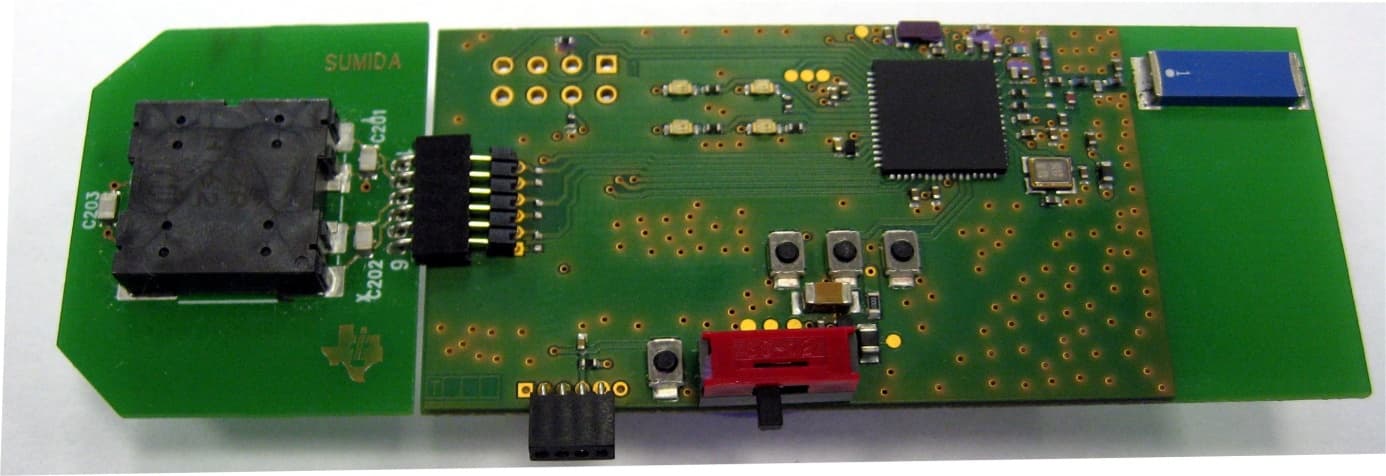
DFORF430F5978
May 04, 2014Development Tool
Equipment Class
DSC - Part 15 Security/Remote Control Transmitter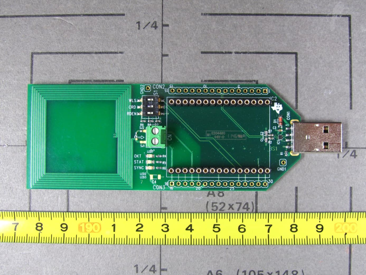
DFOMRD2EVM
Jul 16, 2012RFID Reader
Equipment Class
DCD - Part 15 Low Power Transmitter Below 1705 kHz