DV8DS7100Patient Monitor
Fukuda Denshi Co Ltd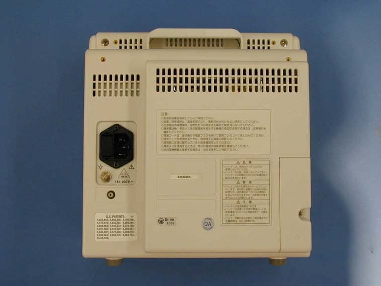
Click to zoom
Application Details
- Equipment Class
- TNB - Licensed Non-Broadcast Station Transmitter
- Date of Grant
- Dec 09, 2003
- Application Purpose
- Original Equipment
- Date of Application
- Dec 09, 2003
- Equipment Note
- Patient Monitor
- Frequency Range
- 608.01250000 - 613.98750000
- Company
- Fukuda Denshi Co Ltd
- Country
- Japan
Documents & Files
Document Text
Text extracted from the exhibit documents filed with the FCC. Open a document above to read the original.
Users Manual
i Preface Thank you for purchasing this product. Before using this product, read the following precautions to make sure the product is used correctly and safely. Safety Precautions ii Labels Attached to the Unit ii Measurement Unit for Each Parameter iv Graphic Symbols v Precautions for Safe Operation of Medical Electrical Equipment vi Precautions for Safe Operation of Medical Telemetry (DS-7141, DS-7101LT) vii Precautions about the Maintenance viii Precautions about the Pacemaker ix Non-Explosion Proof ix Defibrillation Safety ix Electrosurgery Safety x Precautions about Magnetic Resonance Imaging x Precautions about Connections to Peripheral Devicesxi Precautions about the Fuse xi Accessories and Optional Accessories xi Precautions about the DS-7100 System xii Precautions for Use of SpO 2 Sensor xviii Precautions for Use of NIBP Cuff xviii Disposing of Equipment, Accessories, or Components xviii Precautions about Transportation xviii Precautions about RTC or Data Backup xviii Precautions for Use of Lithium-Ion Battery Pack xix To Prepare for Emergency Use xx Electromagnetic Compatibility xxi Precautions for Safe Operation under Electromagnetic Influence xxi EMC Guidance xxi Compliance to the Electromagnetic Emissionsxxii Compliance to the Electromagnetic Immunity (1) xxii Compliance to the Electromagnetic Immunity (2) xxiii Recommended Separation Distances between Portable and Mobile RF Communications Equipment and the DS-7100 System xxiv ii Safety Precautions ? Read the “Safety Precautions” thoroughly before use to ensure correct and safe use of the product. ? Be sure to follow the precautions indicated below, as these are important messages related to safety. DANGER Failure to follow this message may cause immediate threat of death or serious injury, or complete failure of the equipment. WARNING Failure to follow this message may result in death or serious injury, or complete failure of the equipment. CAUTION Failure to follow this message may cause injury or failure to the equipment. NOTE A note is not related to product safety, but provides information about the correct use and operating procedures to prevent incorrect operation and malfunction of the equipment. Labels Attached to the Unit Make sure to read the warning labels attached to the unit and comply with these requirements while operating the unit. CAUTION Do not damage or erase the warning labels attached to the unit. These warning labels contain descriptions important for handling and operating the unit properly and safely. A damaged label may compromise safe operation. iii DS-7100 System DANGER Risk of explosion if used in the presence of flammable anesthetics. CAUTION Before connecting, read instruction manual. CAUTION To reduce the risk of electric shock, do not remove the cover. Refer servicing to qualified service personnel. DANGER ? Use only the batteries specified for this device. ? Do not disassemble or modify the battery. The battery incorporates protection circuitry for safety purposes. WARNING ? Installation of the battery should be performed only by our service representative, to avoid any risk of electric shock to the operator or malfunction of the device. CAUTION ? The life cycle of the battery is 1 year. ? The battery charges when the power cord is connected to a hospital-grade outlet. ? It takes approximately 2.5 hours to fully charge an empty battery. iv Measurement Unit for Each Parameter The measurement units for this equipment are as follows. DetailParameterDisplayUnitDefault ECGHR bpm (beats per minute) Invasive Blood Pressure PR_BP bpm (beats per minute) Heart RatePulse Rate *1 SpO 2 PR_SpO 2 bpm (beats per minute) ST LevelECGSTmm, mvmv VPCECGVPCbeats / hour Impedance Respiration RR_IMP Bpm (breaths per minute) Respiration Rate *2 CO 2 RR_CO 2 Bpm (breaths per minute) Impedance Respiration APNEAs (second) Apnea CO 2 APNEAs (second) Invasive Blood Pressure Invasive Blood Pressure BPmmHg, kpammHg Non-Invasive Blood Pressure Non-Invasive Blood Pressure NIBPmmHg, kPammHg Arterial Oxygen Saturation SpO 2 SpO 2 % TemperatureTemperatureTEMP ?C / ?F?C End-Tidal CO 2 Concentration CO 2 EtCO 2 mmHg, kPa, %mmHg Inspiratory CO 2 Concentration CO 2 InspCO 2 mmHg, kPa, %mmHg *1HR/PR will be displayed in the color selected for ECG/HR. *2RR will be displayed in the color selected for RESP. v Graphic Symbols The following symbols are used for this equipment. DS-7100 System: Main Unit SymbolDescription Caution; refer to accompanying documents Indicates the need to refer to related accompanying documents before operation. Equipotential Terminal Indicates the terminal to equalize the potential difference when interconnecting the devices. DS-7100 System: Symbols displayed on the screen SymbolDescription Battery Mark Indicates battery capacity and remaining volume during battery operation. Alarm OFF Indicates the alarm is OFF. Heart Rate Synchronization Mark This mark flashes synchronizing to the heartbeat. Respiration Synchronization Mark This mark flashes synchronizing to the inspiration. Event Key Mark Displayed when an alarm generates. ON/OFF of the display can be selected on the ward setup. Message Mark Displayed in the parameter key when an alarm message is present for that parameter. vi Precautions for Safe Operation of Medical Electrical Equipment CAUTION Read the following precautions thoroughly to correctly operate the device. ? Users should have a thorough knowledge of the operation before using this system. ? Pay attention to the following when installing and storing the equipment. ? Do not install or store in an area where the equipment will be subject to splashing water. ? Do not install or store in an area where the environmental conditions, such as atmospheric pressure, temperature, humidity, ventilation, sunlight, dust, sodium, sulfur, will adversely affect the system. ? Place the equipment on a stable surface where there is no inclination, vibration, or shock (including during transportation). ? Do not i…
Text truncated - open the document above for the full version.
Users Manual
2 1 Basic Operation This chapter describes the basic operation for monitoring. Chapter 2 Before Use Basic Operation for Monitoring 2 Touch Keys 2 General Key Control 2 Key Control for Each Parameter 2 Before Use About the Home Display 3 About the Home Display 3 The Description of the Display 4 Numeric Data, Waveform, Patient Name, etc. 4 Alarm Message for Numeric Data / Arrhythmia 4 Equipment Status Alarm Message 5 Other Bed Alarm Message 5 To Return the Display 6 Preparation for Monitoring To Turn On the Power 7 Connecting the Power Cable 7 To Turn On the Power Switch 8 To Use with the Battery Pack 9 To Start Monitoring 10 Discharge Confirmation at Power ON 10 To Admit a Patient 10 Basic Operation 12 Scale, Lead, Baseline Position Setup (Parameter Key) 12 Scale, Lead, Baseline Position Setup (User Key) 14 Alarm Setup for Each Parameter 15 ON/OFF of Parameter Display Waveform/Numeric Data Display 16 Recording 17 Start / Stop of Waveform Recording 17 To Install the Paper 18 To Suspend Monitoring 19 Discharging Procedure 20 Operation Flow 21 2 Basic Operation 2 2 Before Use Basic Operation for Monitoring Touch Keys All the operation is performed using the touch keys on the screen. CAUTION Always operate the touch screen with fingers or touch screen pen. Do not touch with a pen-point or other hard-edged instruments. Malfunction of the touch screen or damage may result. General Key Control 1. Pressing the Menu key will switch the display with a pip sound. 2. The touch key will respond by pressing any part of the key. 3. Pressing the Home key at any time will return the display to the home display. Key Control for Each Parameter 1. The touch key will respond by pressing any part of the numeric display frame (parameter key). 2. Pressing the Home key at any time will return the display to the home display. Reference Up to 4 frequently used keys can be set as user key. Refer to “4. Monitoring Setup To Set the User Keys” for details. 1 2 3 2 3 Before Use About the Home Display About the Home Display ? The home display appears immediately after the power is turned ON. ? The waveforms and numeric data are displayed on the home display. ? There are 2 modes of home display, “Standard Display (Home)” and “Numeric Data Enlarged Display”, which can be switched by pressing the Home / Enlarge key. Reference The home key function can be selected from Home / Enlarge or Home on the hospital setup menu. The default setting is Home . Refer to “8. System Configuration Hospital Setup” for details. Standard Display (max. 6 waveforms) This display is focused on number of waveforms to be displayed. Up to 6 waveforms can be displayed. Numeric Data Enlarged Display (max. 3 waveforms) This display is focused on the visuality of numeric data. Each numeric data will be displayed large for easier view. Up to 3 waveforms will be displayed on the upper half of the display. Reference The displaying waveforms and numeric data can be selected as desired, and the configured display can be programmed. Refer to “4. Monitoring Setup To Configure the Display” for details. 2 Before Use 2 4 The Description of the Display Other than waveforms and numeric data, patient name, alarm message, status message, etc. will be displayed on the screen. Numeric Data, Waveform, Patient Name, etc. Alarm Message for Numeric Data / Arrhythmia There are 2 types of alarm messages, numeric data alarm message and arrhythmia alarm message. If both alarms occur at the same time, the numeric alarm message and arrhythmia alarm message will be displayed alternately in 2-seconds intervals. Bed ID Patient Name Patient Type Battery Capacity Time Numeric Data Display Area Parameter Key Waveform Display Area Fixed Key, User Key Numeric Data Alarm Message Arrhythmia Alarm Message Telemetry Channel ID 2 5 Equipment Status Alarm Message The equipment status alarm message will be displayed when proper monitoring can not be performed. Other Bed Alarm Message When the monitor is connected to the network, and other bed alarm is turned ON, the alarm occurring at the other bedside monitors will be notified. The other bed alarm message will function as a control key. By pressing the message display, the window to select the alarm generating bed will appear. Pressing the key will display the numeric data and waveforms for that bed. By pressing the Room/Bed ID key for the alarm generating bed, the numeric data and waveforms will be displayed. The Room/Bed ID key for the alarm generating bed will be indicated in red. Reference Refer to “. Function Other Bed Display” Equipment Status Alarm Message Other bed alarm message 2 Before Use 2 6 To Return the Display To Return to the Home Display By pressing the Home key, the display will return to the home display. To Return to the Previous Display By pressing the Prev. Disp. key which will be displayed on each setup window, the previous display will appear. 2 7 Preparation for Monitoring To Turn On the Power Connecting the Power Cable Connect the accompanying AC power cable (CS-34) to the monitor and to the 3-way grounded outlet. When the AC power is supplied to the monitor, the main power lamp will light in green. When the battery pack (optional) is installed, the charge lamp will light and charging will start. WARNING ? Use only the accompanying 3-way AC power cable. Use of other cables may result in electric shock to the patient and the operator. ? The power cable must be connected to AC 115V hospital grade outlet. ? When using multiple ME equipment simultaneously, perform equipotential grounding to prevent potential difference between the equipment. Even a small potential difference may result in electric shock to the patient and the operator. Power Supply Connector Charge Lamp This lamp will light in orange during charging. It will turn to green when the charging is complete. Main Power Lamp This lamp will light in green when the AC power is supplied. The lamp will be extinguished during battery operation. 2 Preparation for Mon…
Text truncated - open the document above for the full version.
Users Manual
2 11 Press the ID key. Enter the ID number using the numeric keypad. 3.Enter the patient’s birth date. Press the Age key. Enter the birth date using the numeric keypad. 4.Select the patient type, and Used / Not used of pacemaker use. Select the patient type from Adult , Child , or Neonate . Select the pacemaker use from Used , Not used . WARNING The patient type and pacemaker use must be selected. The patient type selection influences the precision of the QRS detection and NIBP measurement. Make sure the correct selection is made. 2 To Start Monitoring 2 12 Basic Operation Scale, Lead, Baseline Position Setup (Parameter Key) 1.Select the parameter to set the scale / lead / baseline position. (Ex.: ECG) Press the parameter key where heart rate is displayed. 2.Press the Lead Size key. The menu to adjust size / lead / baseline position will be displayed. 3.Adjust the waveform size. Select an appropriate waveform size for the monitoring waveform. CAUTION The arrhythmia detection level corresponds with the displayed waveform size. Select an appropriate size for monitoring. 2 13 4.Select the lead. Select an appropriate lead according to the monitoring purpose. 5.Adjust the baseline position. Use the ? , ? keys to adjust the waveform baseline position. Reference Use the same procedure for each parameter. Refer to section for each parameter in “6. Parameter Setup”. 2 Basic Operation 2 14 Scale, Lead, Baseline Position Setup (User Key) Pressing the Lead Size key will display the arrow keys on the home display to adjust waveform size, scale, lead, baseline position. 1.Select the waveform size, lead, baseline position for ECG waveform. Adjust the waveform suitable for monitoring. Pressing the Lead key will sequentially change the lead. 3-electrode: 4-electrode: aVR aVL aVF 5-electrode: aVR aVL aVF V Pressing the Size key will sequentially change the size. 1/4 1/2 1 2 4 1/4 Use the , keys to adjust the baseline position up or down. 2.Select the scale for BP, CO 2 waveform. Pressing the Scale key will sequentially switch the scale. 3.Select the waveform size for impedance respiration waveform, SpO 2 waveform. Pressing the Size key will sequentially change the size. 1/4 1/2 1 2 4 1/4 2 15 Alarm Setup for Each Parameter The alarm can be set for each parameter. By pressing the selected parameter key, upper and lower alarm limit and ON/OFF of alarm can be set. 1.Select the parameter to set the alarm. (Ex.: HR alarm) 2.Press the HR Alarm key. The menu to adjust the alarm limit will be displayed. 3.Set the upper and lower alarm limit. Use the ? , ? keys to adjust the lower limit. Use the ? , ? keys to adjust the upper limit. Reference Use the same procedure for the setup of each parameter. Refer to section for each alarm in “6. Parameter Setup” Lower Limit Upper Limit 2 Basic Operation 2 16 ON/OFF of Parameter Display Waveform/Numeric Data Display The waveform and numeric data display for each parameter can be turned ON or OFF without changing the display configuration. If not performing the ECG or SpO 2 measurement while the ECG cable or SpO 2 sensor is connected to the monitor, the equipment status alarm such as “Lead Off” will generate. Removing ECG or SpO 2 from the display configuration will not generate such alarm, but this function may be more useful as it allows to turn off the measurement without changing the display configuration. This function is not available for NIBP monitoring. 1.Select the parameter to turn off the display. (Ex.: ECG) 2.Press the Display ON/OFF key. The confirmation display for ON/OFF of ECG display will appear. 3. Select Display ON or Display OFF . Pressing the Display ON key will display the waveform and numeric data. Pressing the Display OFF key will not display the waveform and numeric data. 4. Automatic reset For ECG, impedance RESP, SpO 2 , CO 2 , properly connecting the sensor will automatically set the display ON/OFF function to “Display ON”. Reference For automatic reset condition, refer to Display ON/OFF section for each parameter in “6. Parameter Setup”. The Display OFF message will be displayed inside the parameter key. 2 17 Recording Start / Stop of Waveform Recording Pressing the Rec. START/STOP key on the home display will start the waveform recording. Up to 3 waveforms can be recorded. Example of Recording Reference For the manual recording, number of recording waveforms and recording duration can be set. Refer to “4. Monitoring Setup Manual Recording” for details. For the alarm recording, number of recording waveforms, recording duration, alarm factor can be set. Refer to “4. Monitoring Setup Alarm Recording” for details For the periodic recording, number of recording waveforms, recording duration, recording intervals can be set. Refer to “4. Monitoring Setup Periodic Recording” for details. The monitoring data of the patient such as graphic trend and tabular trend can be recorded. Refer to sections on graphic trend and tabular trend in “7. Function”. Bed ID Patient Name Waveform Type, Lead, Size Recording Speed Rec. Mode Delay Time Telemetry Channel Filter Mode Recorded Time Sex Age Patient ID Patient Type Measured Data 2 Basic Operation 2 18 To Install the Paper 1.Press the button located at the right side of the recorder magazine. 2.The magazine will come out. 3.Pull out the magazine from the monitor. 4.Set the recording paper so that the mark printed on each paper comes to the right. 5.Place the magazine back into the monitor. Push in until it locks into place with a click sound. Mark 2 19 To Suspend Monitoring When not monitoring for a while, turning OFF the power will erase the recall data, ST measurement, OCRG data. However, using the cease monitoring function allows suspension of data measurement, alarm generation, automatic measurement, automatic recording without erasing the data or setup details. 1. Press the Cease key on the admit / discharge menu. Press the Menu Admit / Discharge Cease key. 2. Suspend monitoring. Pressing the OK key on the confi…
Text truncated - open the document above for the full version.
Users Manual
3 1 Vital Application This chapter describes the procedure for vital application, etc. Chapter 3 To Acquire ECG Waveform 2 Before Attaching the Electrodes 2 Electrode Placement 3 Connection to the Patient Monitor 4 About the Arrhythmia Analysis 5 QRS Classification 5 Arrhythmia Type 5 Filter Selection 6 Filter Mode Setup 6 Procedure for Filter Mode Selection 7 AC Filter 7 Lead Cable Types 7 Respiration (Impedance Measurement) 8 To Measure the SpO 2 9 Functional and Fractional Saturation 12 Measured Versus Calculated Saturation 12 To Measure the NIBP 14 Procedure for Periodic Measurement 16 To Measure the BP 17 To Measure the CO 2 Concentration (DS-7141)21 Patient Application and Display 21 Procedure for Calibration (Every 6 Months) 22 To Measure the Temperature 24 3 Vital Application 3 2 To Acquire ECG Waveform Before turning ON the power 1. Check the grounding.2. Check the recording paper.3. Turn ON the power. The magazine will be released by pressing the magazine release button. Properly ground using the 3-way AC plug. The grounding is required to prevent AC noise. Open the recorder magazine, and check that there is enough amount of paper installed. Turn ON the power and check for appropriate display. Before Attaching the Electrodes 1.Clean the electrode sites with an alcohol swab or other skin preparation. If necessary, shave the electrode sites to remove excessive hair. 2.Peel off the backing of disposable electrode. Pay attention not to touch the electrode jelly. 3 3 Electrode Placement There are 3-electrode, 4-electrode, 5-electrode application depending on the cable type. Using the 4-electrode or 5-electrode application allows simultaneous monitoring of 2 ECG waveforms, and high accuracy of arrhythmia analysis can be attained. Also, the displayed lead type can be changed. For 3-electrode lead (1 waveform monitoring) Lead Type / / SymbolColorElectrode Site RAWhiteOn the right infraclavicular fossa LABlackOn the left infraclavicular fossa LLRed On the left midclavicular line, near the supracrestal line. For 4-electrode lead (Simultaneous 2 waveforms monitoring) Lead Type / / / aVR / aVL / aVF SymbolColorElectrode Site RAWhite On the right infraclavicular fossa LABlack On the left infraclavicular fossa LLRed On the left midclavicular line, near the supracrestal line. RLGreen On the right midclavicular line at the same height as F. For 5-electrode lead (Simultaneous 2 waveforms monitoring) Lead Type / / / aVR / aVL / aVF / V SymbolColorElectrode Site RAWhiteOn the right infraclavicular fossa LABlackOn the left infraclavicular fossa LLRed On the left midclavicular line, near the supracrestal line. RLGreen On the right midclavicular line at the same height as F. VBrown Chest Lead (V1 V6) 3 To Acquire ECG Waveform 3 4 Connection to the Patient Monitor 1.Connect the lead cable to the electrode. Clip on the lead cable end to the electrode convex part. CAUTION ? The indication for continuous use of the electrode is about one day. ? Replace the electrode if the skin contact gets loosen due to perspiring, etc. ? When an electrode is attached at the same location for a long time, some patients may develop a skin irritation. Check the patient’s skin condition periodically and change the electrode site as required. 2.Connect the lead cable to the relay cable. 3.Plug in the relay cable to the ECG input connector (green) of the patient monitor. 4.Verify that the ECG waveform is displayed on the monitor. Adjust the waveform size and position. The monitoring lead can be also changed. Reference Refer to “ 6. Parameter Setup ECG” for size / lead setup. 3 5 About the Arrhythmia Analysis Arrhythmia Analysis Flow Learn Waveform QRS Judgement VPC? Pattern Matching VPC! Arrhythmia The arrhythmia detection algorithm learns the normal waveform of the patient and compares the waveform (QRS pattern) and RR interval for each heartbeat to determine the VPC. It compares the parameters such as QRS amplitude, QRS width, QRS polarity, RR interval, and selects abnormal QRS. Then the QRS with suspected VPC is pattern matched to distinguish the noise and VPC. This will finally determine the VPC and generate the arrhythmia alarm. QRS Classification Each heartbeat will be classified to the following patterns according to the QRS judgement. N (Normal)Normal QRS beat V (VPC)Ventricular Extrasystole S (SVPC)Supraventricular Extrasystole P (Pacing Beat)Pacing beat F (Fusion Beat)Fusion beat of pacing and spontaneous beat ? (Undetermined Beat)Learning arrhythmia, or beat not matching the pattern Arrhythmia Type With the above QRS judgement, the following 12 types of arrhythmia alarm can be generated. TypeMeaningDetection Criteria ASYSTOLECardiac Arrest Cardiac arrest is detected for more than preprogrammed time. VFVentricular Fibrillation A random, rapid electrical activity of the heart is detected. VTVentricular Tachycardia 9 or more continuous ventricular beats are detected. (HR: 140bpm / 120bpm or over) SLOW_VT 9 or more continuous ventricular beats are detected. (HR: under 140bpm / 120bpm) TACHYTachycardiaHR is over the upper alarm limit. BRADYBradycardiaHR is below the lower alarm limit. RUNConsecutive VPC Continuous VPC exceeding the preprogrammed value is detected. COUPLET Couplet Ventricular Extrasystole 2 continuous beats of VPC is detected. PAUSECardiac arrest of 1.5 seconds and over is detected. BIGEMINYVentricular BigeminyQRS pattern of V-N-V-N-V-N is detected. TRIGEMINYVentricular TrigeminyQRS pattern of V-N-N-V-N-N is detected. FREQUENTFrequent VPC VPC exceeding the preprogrammed value is detected within 1 minute. 3 To Acquire ECG Waveform 3 6 Filter Selection Filter Mode Setup The waveform frequency characteristic can be selected from Monitor Mode, ESIS Mode, or ST Display Mode according to the monitoring purpose. 1. Monitor Mode Frequency Characteristic Adult / Pediatric 0.5 40Hz Neonate 1.6 40Hz This is the standard mode for ECG monitoring. The upper frequency is set to 40Hz to reduce artifact caused by EMG, …
Text truncated - open the document above for the full version.
Users Manual
3 14 To Measure the NIBP 1.Select the appropriate cuff type for the patient. According to the AHA (American Heart Association) guideline, the appropriate cuff width is 40% of the arm circumference. Select the appropriate cuff from the following selections. Infant Cuff CUF-7105 Width 8.5cm Pediatric Cuff CUF-7104 Width 10.5cm Adult Cuff (small) CUF-7103 Width 11cm Adult Cuff (medium) CUF-7102A Width 14.5cm Adult Cuff (large) CUF-7101 Width 17cm 2.Connect the cuff to the air hose, and then connect the air hose to the cuff connection connector on the monitor. 3.Apply cuff to the patient. Position the ARTERY mark over the artery on the patient’s arm and wrap the cuff around. A finger should just fit in between the cuff and arm. 3 15 Check Point Align the cuff height and heart position to eliminate an error caused by the blood weight. It is most appropriate to measure with the patient lying down and arms naturally extended. 4.Start the measurement. Pressing the NIBP START/STOP key will start inflating the cuff pressure and starts the measurement. Upon completion, the measured value will be displayed inside the NIBP parameter key. WARNING Before the measurement, make sure the patient type ( Adult / Child / Neonate ) is properly selected. Otherwise, correct measurement can not be performed, and congestion or other injury may result. CAUTION ? Pay attention when measuring the NIBP of patient with bleeding disorders or hypercoagulation. The cuff inflation may cause petechia or circulatory failure by the blood clot. ? If the air hose is twisted, or weighed down, the cuff air can not be exhausted. Properly arrange the cuff and air hose. 3 To Measure the NIBP 3 16 Procedure for Periodic Measurement 1.Press the NIBP parameter key on the home display. The NIBP setup menu will be displayed. 2.Press the Auto Mode key on the NIBP setup menu. The interval time setup menu will be displayed. 3.Select an interval time. Press the key for the desired interval. Check that the key LED is lighted for the selected interval. The measurement will automatically start at the selected interval. The measurement time will be integral multiple of the selected interval time starting from 0 minute. Ex.) If the present time is 13:14, the measurement time will be as follows for each interval time. 2 min.: 13:16, 13:18, 13:20, ... 2.5 min.: 13:15, 13:17:30, 13:20, ... 3 min.: 13:15, 13:18, 13:21, ... 5 min.: 13:15, 13:20, 13:25, ... 3 17 To Measure the BP 1.Connect the 2ch BP conversion cable to the monitor and interface cable. 2 channels of BP can be measured on this monitor. Connect the monitor and the interface cable via 2ch BP conversion cable. 2.Assemble the BP measurement device. The following procedure explains the case when BP transducer (COBE CDX series, No.041-575- 504) is used. If using other transducers, refer to the operation manual for the corresponded transducer. (1)Check if the package of the transducer is not damaged before opening. Verify that each connector is securely connected. (2)Align the bracket to patient’s heart position (about 1/2 of the chest depth). 2ch BP Conversion Cable Interface Cable 3 To Measure the BP 3 18 (3)Inject the heparin 1000 units to saline bag, mix thoroughly and puncture the infusion line through the same hole. Set the saline bag to pressure bag, and hang from the infusion device. Fill saline to about 1/3 of the drip. (4)After loosening the zero-port plug, push the flash button to perform priming to remove air bubbles. (5)Verify that all air bubbles are removed, and tighten the zero-port plug. Turn on the zero-port plug side of the open-air three-way cock. (6)Inflate the pressure bag to 300mmHg. (7)Wait about 5 minutes after setting the blood pressure device. Next procedure is to perform the zero balance. 3 19 2.Perform zero balance. (1)Loosen the zero-port plug on open-air three-way cock one-half turn. (2)Press the BP parameter key on the home display. The display will proceed to BP setup menu. (3)Press the BP Zero key on the BP setup menu. Zero balance will start. (4)Turn off the zero-port plug side of the open-air three-way cock. (5)Connect the catheter to the end of monitoring line. The preparation for measurement is complete. 3 To Measure the BP 3 20 3.Start the BP monitoring. Start the BP measurement. Press the Home key. Verify that the BP waveform and each measurement value is displayed on the home display. CAUTION If the SYS value is abnormally high, or DIA is abnormally low, a resonance may be the cause. If the resonance can not be eliminated by adjusting the blood pressure filter, check the BP line and use a thick, short, and hard catheter. CAUTION The zero balance procedure is required for the following case. ? When starting a measurement. ? When the heart position has changed due to body movement. ? When the transducer position has changed. ? When measuring for a long period of time and there is a possibility of measurement error due to change in ambient temperature, etc. ? When a connector is connected / disconnected, or a transducer is replaced. 3 21 To Measure the CO 2 Concentration (DS-7141) The DS-7141 incorporates CO 2 measuring unit. Patient Application and Display 1.For intubated patient (1)Attach the airway adapter to respiration circuit. (2)Remove the protective cap on the airway adapter, and connect to the sampling tube. (3)Connect the other end of the sampling tube to the patient monitor. Verify that all the tubes are properly connected. WARNING ? Use the specified sampling tube and nasal prong manufactured by Oridion. ? Always consider the circumference of the intubation tube when using the airway adapter. If inappropriate airway adapter is used for a patient with low ventilation, CO 2 may mix in to the inspired air resulting in incorrect measurement, or apnea detection may become difficult. 2.For patient using the nasal prong (1)Attach the nasal prong to the patient. (2)Connect the nasal prong to the patient monitor. Verify that it is properly connected. 3…
Text truncated - open the document above for the full version.
Contact Information
Applicant
Takashi Nomura(General Manager)
Technical Contact
UL Apex Co., Ltd. Yamakita Lab.Toyokazu Imamura
[email protected]81-465-77-1011
907 Kananishi, Yamakita-machi · Ashigarakami-gun · Japan
Technical Specifications
| # | Rule Parts | Frequency Range | Power Output | Emission | Tolerance |
|---|---|---|---|---|---|
| 1 | 95H | 608.0125 MHz - 613.9875 MHz | 1.00 mW | 8K50F1D | 2.5000000000 ppm |
Other Applications from Fukuda Denshi Co Ltd
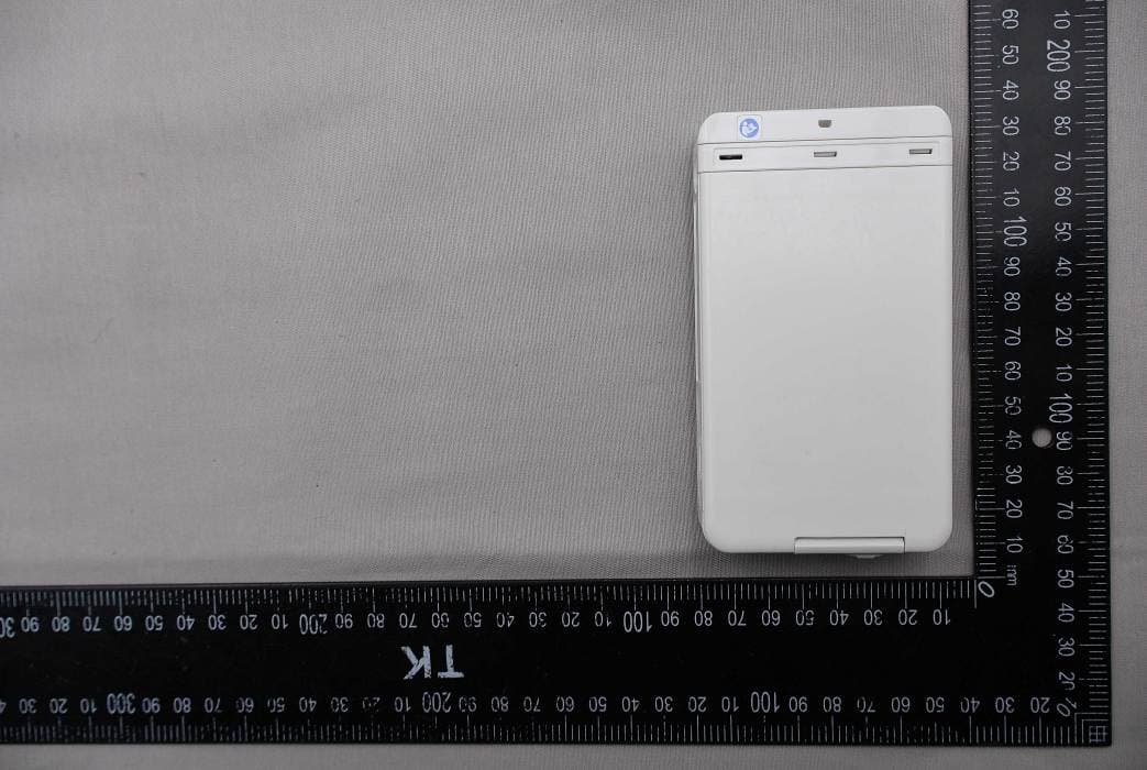
DV8DSX1N
Jan 07, 2026DS-X Series ECG, Respiration and SpO2 Transmitter
Equipment Class
DXX - Part 15 Low Power Communication Device TransmitterDV8LX13002
Dec 03, 2025ECG, Respiration and SpO2 Transmitter
Equipment Class
DXX - Part 15 Low Power Communication Device TransmitterDV8LX13001
Dec 01, 2025ECG, Respiration and SpO2 Transmitter
Equipment Class
DXX - Part 15 Low Power Communication Device Transmitter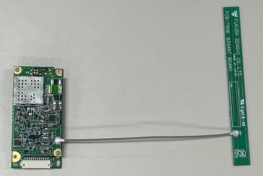
DV8TMX100
Mar 22, 2021TM XMTR Module
Equipment Class
TNT - Licensed Non-Broadcast Transmitter Worn on Body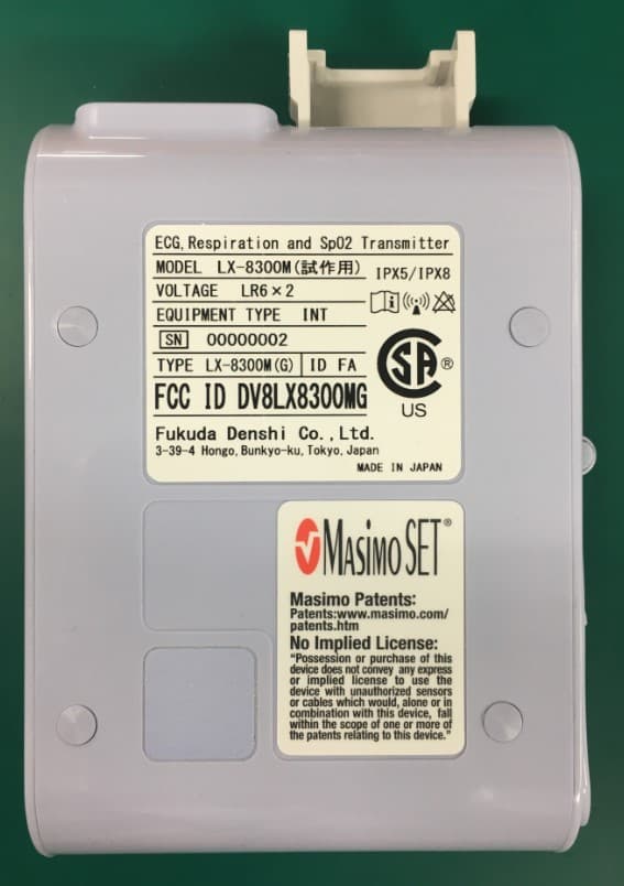
DV8LX8300MG
May 28, 2020ECG,Respiration and SpO2 Transmitter
Equipment Class
TNT - Licensed Non-Broadcast Transmitter Worn on Body