DV8HLX561ATelemetry Transmitter Module
Fukuda Denshi Co Ltd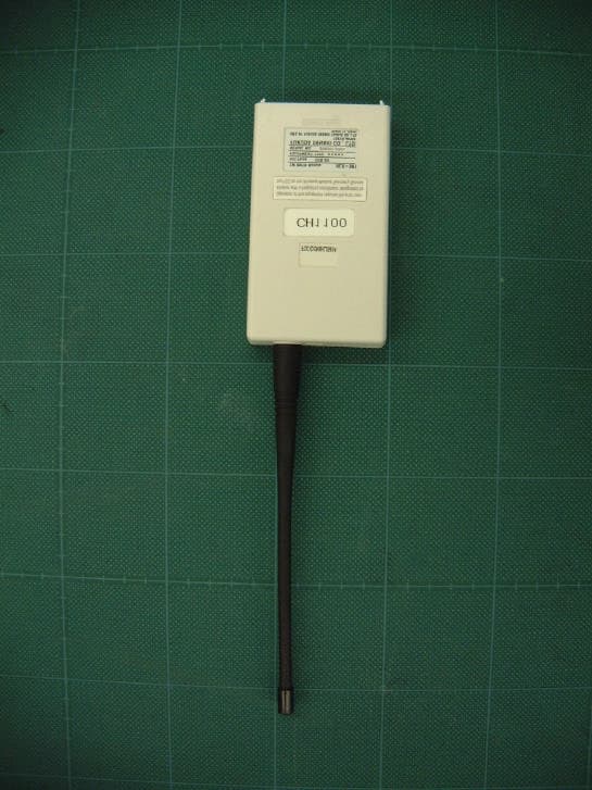
Click to zoom
Application Details
- Equipment Class
- TNB - Licensed Non-Broadcast Station Transmitter
- Date of Grant
- Oct 03, 2002
- Application Purpose
- Original Equipment
- Date of Application
- Oct 03, 2002
- Equipment Note
- Telemetry Transmitter Module
- Frequency Range
- 608.01250000 - 613.98750000
- Company
- Fukuda Denshi Co Ltd
- Country
- Japan
Documents & Files
Document Text
Text extracted from the exhibit documents filed with the FCC. Open a document above to read the original.
Cover Letter(s)
2-35-8 HONGO BUNKYO-KU TOKYO 113 JAPAN Phone 81-3-5684-1300 Fax 81-3-5684-1321 Request for Confidentiality Date: August 3, 2002 American Telecommunications Certification Body, Inc. 6731 Whittier Avenue Suite C110 McLean, VA 22101 RE: Certification Application FCC ID: DV8HLX561A We, Fukuda Denshi Co., Ltd. request that the following information is to be held confidential pursuant to CFR 47, Section .457 and .459. Block Diagram Schematics Parts List Technical Description Tune Up Specification These contain schematic and operational details of the product for which certification is being sought. This information is classified as “Company Confidential” and disclosure of these exhibits would potentially be harmful to our business because this product incorporates innovative lowpower RF transmitter design techniques, ECG processing technology, and other such details that would be useful to a competitor in the medical telemetry business. This information is not available to the public since all service and repairs are done on a sub-assembly basis and the design details are hidden. It is expected that this information would remain sensitive for at least two years from the date of submission. Thank you for your attention to this matter. Yoshi Muraki General Manager Engineering Development Department
Cover Letter(s)
2-35-8 HONGO BUNKYO-KU TOKYO 113 JAPAN Phone 81-3-5684-1300 Fax 81-3-5684-1321 Letter Of Agency Date: August 3, 2002 American Telecommunications Certification Body, Inc. 6731 Whittier Avenue Suite C110 McLean, VA 22101 To Whom It May Concern: Please be advised that Fukuda Denshi Co., Ltd. authorizes A-Pex International Co., Ltd. to act on our behalf, until otherwise notified, for applications submitted to American Telecommunications Certification Body, Inc. (ATCB). We certify that we are not subject to denial of federal benefits, that includes FCC benefits, pursuant to Section 5301 of the Anti-Drug Abuse ACT of 1988, U.S.C. 862. Further, no party, as defined in 47 CFR 1.2002(b), to the application is subject to denial of federal benefits, that includes FCC benefits. Thank you for your attention to this matter. Yoshi Muraki General Manager Engineering Development Department
Cover Letter(s)
American Telecommunications Certification Body Inc. 6731 Whittier Ave, McLean, VA 22101 September 26, 2002 RE: FCC ID: DV8HLX561A Attention: I have a few comments on this Application. 1 The following pdf files contain undetermined fonts that cannot be opened by the FCC server. Please remove all undefined fonts and provide pdf files that can be opened. confidential_Schematics1.pdf confidential_Schematics2.pdf confidential_Schematics3.pdf HLX-561 User's Manual.pdf 2 FYI, no response needed. Please note that ANSI C83.4 is not a test procedure for licensed devices. You should refer to proper test methodologies for licensed devices such as EIA/TIA 603-A-1. 3 The rf exposure statement refers to 2.1093(d)(2). This section is for portable devices used within 20cm of the body. The device in question appears to fit into or with a bedside monitoring system that will put the device significantly further than 20cm from the body. Thus, the device would not be portable under 2.1093 but mobile under 2.1091. This would mean that MPE calculations and a 20cm separation warning statement in the manual are sufficient for this device. Please explain why you refer to 2.1093 and provide adequate rf exposure evaluation documentation, or alternately revise the manual to include the 20cm separation statement for mobile devices and provide MPE calculation. 4 Please note that the test procedure you specified in the radiated spurious emissions paragraph on page 5 of your report is good only for those emissions at the band edge. All other out of band emissions are QP only. Please clarify that only the band edges were tested in this manner and that all other out of band emissions were tested using the QP function of the analyzer. Dennis Ward mailto:[email protected] The items indicated above must be submitted before processing can continue on the above referenced application. Failure to provide the requested information may result in application termination. Correspondence should be considered part of the permanent submission and may be viewed from the Internet after a Grant of Equipment Authorization is issued. Please do not respond to this correspondence using the email reply button. In order for your response to be processed expeditiously, you must submit your documents through the AmericanTCB.com website. Also, please note that partial responses increase processing time and should not be submitted. Any questions about the content of this correspondence should be directed to the sender.
External Photos
A- PEX INTERNATIONAL CO., LTD. □HEAD OFFICE 4383-326 Asama-cho, Ise-shi, Mie-ken 516-0021 Japan TEL:0596-24-6717/FAX:0596-24-8020 Date: October 3, 2002 RE: Fukuda Denshi Co., Ltd. FCC ID: DV8HLX561A Dear Mr. Dennis Ward, Regarding the above referenced application, please find our reply to the comments dated September 26, 2002: 1) We revised and uploaded the following documents: Schematics 1, Schematics 2, Schematics 3, Users Manual. 2) Thank you very much for your advice on test methodologies. 3) We modified RF Exposure Information document and added the 20cm separation statement in the manual. Please find revised RF Exposure Information and Users Manual. 4) We included the explanation in the test report that all other out of band emissions than the band ages were tested using the QP function of the analyzer. Please refer to uploaded revised page 10 of test report No. 22KE0008-YK. As for additional comments on emission designator and conducted power, please see the following replies: Emission Designator : As described on FCC Part 2.202.(c).(1) and (2), we used the formula of item (g) to derive the emission designator listed on Form 731. Conducted Power : We modified the conducted power on Form 731. Please refer to the revised Form 731. We hope the above replies are satisfactory. We hope all the above replies are satisfactory. Best regards, Yukari Ito (Ms.) A-Pex International Co., Ltd.
External Photos
Fukuda Denshi Co., Ltd. FCC ID: DV8HLX561A External Photo Front View 1 Fukuda Denshi Co., Ltd. FCC ID: DV8HLX561A Front View 2 Fukuda Denshi Co., Ltd. FCC ID: DV8HLX561A Rear View Fukuda Denshi Co., Ltd. FCC ID: DV8HLX561A Top View Bottom View Fukuda Denshi Co., Ltd. FCC ID: DV8HLX561A Left Side View Right Side View
ID Label/Location Info
Fukuda Denshi Co., Ltd. FCC ID: DV8HLX561A Label Information Front View
Internal Photos
Fukuda Denshi Co., Ltd. FCC ID: DV8HLX561A Internal Photo PCB Component Side Fukuda Denshi Co., Ltd. FCC ID: DV8HLX561A PCB Solder Side
RF Exposure Info
RF Exposure Statement No. : 22KE0008-YK Applicant : FUKUDA DENSHI Type of Equipment : TEREMETRY TRANSMITTER MODULE Model No. : HLX-561 FCC ID : DV8HLX561A A-PEX International Co., Ltd. YAMAKITA LAB. 907 Kawanishi, Yamakita-machi, Ashigarakami-gun, Kanagawa-ken, 258-0124 JAPAN Telephone : int +81 465 77 1011 Facsimile : int +81 465 77 2112 Page 1 RF Exposure Statement: Fukuda Denshi Model : HLX-561 complies with FCC radiation exposure requirement specified in the FCC Rules 2.1091(b). Fukuda Denshi Model : HLX-561 has 0.85mW of conducted Peak output power and 1.08mW of EIRP.(Antenna gain : 0.4dBi) According to RF output power of this module transmitter, values for both Conducted peak output power and EIRP are below 5mW.This kind of equipment hardly ever go over SAR value limited of 1.6W/Kg for public resident which is regulated by "OET Bulletin65, Supplement C". Notice in Installation Manual FCC Radiation Exposure Statement: This equipment complies with FCC radiation exposure limits set forth for an uncontrolled environment. This equipment should be installed and operated with minimum distance 20cm between the radiator and your body(excluding extremities : hands, wrists, and feet). and must not be co-located or operated with any other antenna or transmitter. RF Exposure Calculations: The following information provides the minimum separation distance for the highest gain antenna provided with the “HLX-561” as calculated from FCC OET 65 Appendix B, Table (B) Limits for General Population / Uncontrolled Exposure. This calculation is based on the highest EIRP possible from the system, considering maximum power and antenna gain, and considering a 1.0m W/cm^2 uncontrolled exposure limit. The Fires formula used was: S = (P * G) / (4* π * r^2) or r = (P * G) / (4 *π* S) Where S = 1.0 mW/cm^2 for 2400 MHz P = 0.85 mW (Maximum Conducted Power) G = 1.04(λ/4 mono-pole antenna gain : Converted absolute value) r = Minimum safe distance from antenna (cm) For: HLX-561 r = 0.27 cm
Test Report
FCC:ID : DV8HLX561A Test report No. : 22KE0008-YK-A Page : 10 of 48 Issued date : July 23, 2002 Revised date : September 18 A-pex International Co., Ltd. YAMAKITA LAB. 907 Kawanishi, Yamakita-machi, Ashigarakami-gun, Kanagawa-ken, 258-0124 JAPAN Telephone: int +81 465 77 1011 Facsimile: int +81 465 77 2112 MF060b(23.04.02) 5.3 § 95.1115(b) Out of Band Emissions(Radiated) Test Procedure EUT was placed on a platform of nominal size, 1m by 1.5m, raised 80cm above the conducting ground plane. I/O cables that were connected to the peripherals were bundled in center. They were folded back and forth forming a bundle 30cm to 40cm long and were hanged 40cm height to the ground plane. Test was made with the antenna positioned in both the horizontal and vertical planes of polarization. The measurement antenna was varied in height above the conducting ground plane to obtain the maximum signal strength. The Radiated Electric Field Strength intensity has been measured on an open test site with a ground plane and at a distance of 3m. The measuring antenna height was varied between 1 to 4m and EUT was rotated a full revolution in order to obtain the maximum value of the electric field intensity. The measurements were performed for both vertical and horizontal antenna polarization. EUT emission levels were compared when the EUT antenna position was vertical polarization and horizontal polarization. It was opened under transmitting mode. Radiated Spurious emissions The result was also satisfied the general limits specified in Sec.95.1115(b). To determine the level of band-edge spurious, we use the following procedure: Set the resolution bandwidth to 1 kHz in the peak detector mode. Measure the maximum level of the in-band channel closest to the band edge and the maximum level of the out-of-band emissions close to the same band edge. Determine the ratio of the in-band signal to the out-of-band emissions. Then, measure the level of the in-band channel in CISPR quasi-peak mode with 120 kHz bandwidth. Using the ratio obtained, we calculate the equivalent level of the out-of-band emissions to determine compliance with the limits. The emission tests, except for the band edge, were performed with the quasi-peak mode of the test receiver. (Bandwidth:120kHz) Measurement range : 30MHz to 1000MHz CISPR QP Detector, IF BW 120kHz : 1GHz to 7GHz AV Detector Test data : APPENDIX Page27 to 32 (30 –1000MHz) : APPENDIX Page33 to 38 (1 – 7GHz) : APPENDIX Page39 to 40 (Band Edges:608MHz/614MHz, Restricted band Charts) Photographs of test setup : Page14 Test result : Pass Test instruments : KCC-20/21/22/23/29,KCC-D1/D2,KCC-D3,KBA-02,KLA-02,KHA-02, KAF-03,KAF-04,KAT6-03,KSA-02,KTR-04,KOTS-02
Test Report
17725 NE 65 th Street • Redmond, WA 98052 • Phone 1-800-365-6668 • Fax (425) 869-2018 June 26, 2002 To whom it may concern, Re: Temperature - Frequency stability Certification This letter is to certify that the Temperature – Frequency stability of the HLX-561 telemetry transmitter which is satisfied it’s specification over the operating temperature range. Yoshi Muraki General Manager, Engineering Development Department Fukuda Denshi Co., Ltd. Test report of Frequency Stability EUT : HLX-561, Serial No. =2002012905 Freq. Range : 608 to 614 MHz Freq. Stability : +/-2.5 ppm Operating temp. : +10 to +40 degrees C Date : June. 14. 2002 Manufacture : Fukuda Denshi Co., Ltd. Test engineer : Tamotsu Toya Test site : Fukuda Denshi, Hongo office, Engineering Development Department Temp. Chamber : LHU-112, TABAI ESPEC CORP. Serial No.1571794 Registration No. 224-046-001 Freq. Counter : TR5823H, ADVANTEST Serial No.00570534 Registration No.202-027-001 Measurement result: Temp. degrees C Freq. MHz Diffrence, Hz Diffrence, ppm 0 610.999738 -262 - 0.43 +10 611.000477 +477 +0.78 +20 611.000440 +440 +0.72 +25 611.000000 0 +0.00 +30 610.999860 -140 -0.23 +40 610.999591 -409 - 0.67 +50 610.999371 -629 - 1.03
Test Setup Photos
FCC:ID : DV8HLX561A Test report No. : 22KE0008-YK Page : 13 of 48 Issued date : July 23, 2002 A-pex International Co., Ltd. YAMAKITA LAB. 907 Kawanishi, Yamakita-machi, Ashigarakami-gun, Kanagawa-ken, 258-0124 JAPAN Telephone: int +81 465 77 1011 Facsimile: int +81 465 77 2112 MF060b(23.04.02) Conducted emission FCC:ID : DV8HLX561A Test report No. : 22KE0008-YK Page : 14 of 48 Issued date : July 23, 2002 A-pex International Co., Ltd. YAMAKITA LAB. 907 Kawanishi, Yamakita-machi, Ashigarakami-gun, Kanagawa-ken, 258-0124 JAPAN Telephone: int +81 465 77 1011 Facsimile: int +81 465 77 2112 MF060b(23.04.02) Radiated emission
Contact Information
Applicant
Takashi Nomura(General Manager)
Technical Contact
A-Pex International Co., Ltd. YamakitaToyokazu Imamura
[email protected]+81-465-77-1011
907 Kananishi, Yamakita-machi · Ashigarakami-gun, Kanagawa-ken · Japan
Non-Technical Contact
A-Pex International Co., Ltd.Yukari Ito
[email protected]+81-596-24-8116
Test Firm
UL Japan, Inc.Osamu Watatani
Technical Specifications
| # | Rule Parts | Frequency Range | Power Output | Emission | Tolerance |
|---|---|---|---|---|---|
| 1 | 95H | 608.0125 MHz - 613.9875 MHz | 850.00 µW | 10K5F1D | 2.5000000000 ppm |
Other Applications from Fukuda Denshi Co Ltd
DV8DSX1N
Jan 07, 2026DS-X Series ECG, Respiration and SpO2 Transmitter
Equipment Class
DXX - Part 15 Low Power Communication Device TransmitterDV8LX13002
Dec 03, 2025ECG, Respiration and SpO2 Transmitter
Equipment Class
DXX - Part 15 Low Power Communication Device TransmitterDV8LX13001
Dec 01, 2025ECG, Respiration and SpO2 Transmitter
Equipment Class
DXX - Part 15 Low Power Communication Device Transmitter
DV8TMX100
Mar 22, 2021TM XMTR Module
Equipment Class
TNT - Licensed Non-Broadcast Transmitter Worn on Body
DV8LX8300MG
May 28, 2020ECG,Respiration and SpO2 Transmitter
Equipment Class
TNT - Licensed Non-Broadcast Transmitter Worn on Body