DV8HTC702Bidirectional Wireless Communications Module
Fukuda Denshi Co Ltd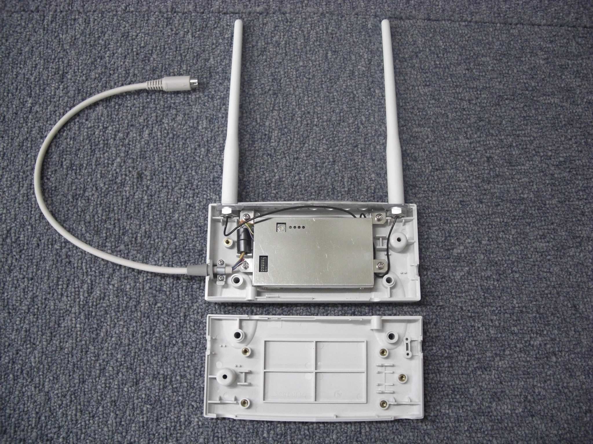
Click to zoom
Application Details
- Equipment Class
- TNB - Licensed Non-Broadcast Station Transmitter
- Date of Grant
- Oct 20, 2010
- Application Purpose
- Original Equipment
- Date of Application
- Oct 20, 2010
- Equipment Note
- Bidirectional Wireless Communications Module
- Frequency Range
- 1395.51250000 - 1396.98750000
- Company
- Fukuda Denshi Co Ltd
- Country
- Japan
Documents & Files
Document Text
Text extracted from the exhibit documents filed with the FCC. Open a document above to read the original.
Users Manual
Bidirectional Wireless Communications Module (TCON) HTC-702 Instruction Manual ● Before using this device, read this “Instruction Manual” thoroughly. ● After reading, keep this manual near the device for future reference. CAUTION Federal Law restricts this device to sale by or on the order of a physician. CAUTION: • The company and product names used in this manual are trademarks or registered trademarks. • If this manual has pages missing or out of order, contact Fukuda Denshi for replacement. • Only physician or persons instructed by physicians are allowed to use the equipment. • The information contained in this document is subject to change without notice due to improvement in the equipment. Copyright © 2010 by Fukuda Denshi Co., Ltd. No part of this document may be copied or transmitted in any form without the prior written permission of Fukuda Denshi Co., Ltd. Printed in Japan i Thank you for purchasing this product. Before using this product, please read through this “Instruction Manual” to make sure the product is used correctly and safely. Even if you are familiar with our devices, there are certain handling procedures that are unique to this device. Therefore, please make sure you read this manual thoroughly before use. Safety Precautions The safety precautions shown in this manual contain important details on the safe use of this product, and must be obeyed. Symbols and their meanings are shown below. Be sure to understand the contents below before reading the rest of the manual. WARNING Failure to follow this message may result in death or serious injury, or complete failure of the equipment. CAUTION Failure to follow this message may cause injury or failure of the equipment. NOTE A note is not related to product safety, but provides information about the correct use and operating procedures to prevent incorrect operation and malfunction of the equipment. ii Precautions for Safety and Hazard Prevention This section contains general information on how to handle this device for safety use. Precautions unique to this device are detailed throughout the manual. CAUTION 1. Users should have a thorough knowledge of the operation before using this device. 2. Pay attention to the following when installing and storing the device. Do not install or store in an area where the equipment will be subject to splashing water. Do not install or store in an area where the environmental conditions, such as humidity, ventilation, sunlight, and air containing dust, salinity, or sulfur, will adversely affect the system. Place the equipment on a stable surface where there is no inclination, vibration, or shock (including during transportation). Do not install or store in an area where chemicals are stored or gasses are evolved. 3. Before operating the device, verify the following items. This equipment is not designed to prevent explosions etc. due to flammable anesthetics or oxygen etc. Therefore, do not use this equipment in a flammable atmosphere. Check that the device is operating normally and safely. Ensure that all cables are firmly and safely connected. Pay special attention when this device is used in conjunction with other devices, as it may cause erroneous judgment and danger. 4. During operation of the device, verify the following items. Make sure the time required for diagnosis, observation, and treatment is not exceeded. Always observe the device and patient to ensure safe operation of the equipment. If any abnormality is found on the device or patient, take appropriate measures such as ceasing operation of the device in the safest way for the patient. Do not allow the patient to come into contact with the device or electronic components. 5. After using the device, verify the following items. Return all operating switches, knobs etc to the position before using the equipment, and then switch off the power. When unplugging the cables, do not apply excessive force by pulling on the cable. Pull by the connector part of the cable. Clean the accessories and cables, and keep them together in one place. Keep the unit clean to ensure proper operation of the next use. iii CAUTION 6. If the device is damaged and in need of repair, users should not attempt to service the device themselves. Label the unit “OUT OF ORDER”, and contact Fukuda Denshi representative. 7. Do not disassemble or remodel the device. 8. Maintenance Check Make sure to periodically check the device and accessories. Before reusing a device that has been left unused for a while, make sure that the device works normally and safely. WARNING This radio frequency device is susceptible to interference from outside sources. Interference may prevent the monitoring of patients connected to this devices. If a problems exists, contact your local service representative. iv Precautions for Use of Bidirectional Wireless Communications (TCON) CAUTION ■To operate the device correctly, read the following precautions carefully. The medical institution (hereinafter referred to as “Institution”) must execute investigation required to prevent interference including types of radio waves, frequencies, and antenna power if wireless equipment is already installed and being used in the facility. Even if this device is installed within the range of radio communication, the communication may not be possible due to noise or multi-path phasing etc. Always consider this thoroughly before use. Do not install this device in an area where it will be subject to splashing water. Water entering the equipment may cause the equipment to malfunction or be damaged. ■In managing, be sure to follow the precautions below. The Institution should appoint a person (hereinafter referred to as the “Overall Manager”) to manage the wireless devices for the whole facility. When installing TCON, the Overall Manager has to receive an explanation of the precautions for use of the TCON from the manufacturer or sales representative. The O…
Text truncated - open the document above for the full version.
External Photos
Fukuda Denshi Co Ltd FCC ID: DV8HTC702 External Photo Front Rear Fukuda Denshi Co Ltd FCC ID: DV8HTC702 External Photo Top Bottom Fukuda Denshi Co Ltd FCC ID: DV8HTC702 External Photo Right Left Cover Open
ID Label/Location Info
Label Location
Internal Photos
Fukuda Denshi Co Ltd FCC ID: DV8HTC702 Internal Photo Side A without Shield Side A with Shield Fukuda Denshi Co Ltd FCC ID: DV8HTC702 Internal Photo Side B
RF Exposure Info
UL Japan, Inc. Shonan EMC Lab. 1-22-3 Megumigaoka, Hiratsuka-shi, Kanagawa-ken, 259-1220 JAPAN Telephone: +81 463 50 6400 Facsimile: +81 463 50 6401 Applicant: FUKUDA DENSHI CO.,LTD. T ype of Equipment : Bidirectional W ireless Communications M odule M odel No. : HTC-702 FCC ID: DV8HTC702 FUKUDA DENSHI CO.,LTD. declares that Model : Bidirectional Wireless Communications Module complies with FCC radiation exposure requirement specified in the FCC Rules 2.1091. The “HTC-702“ has 35.25 mW of EIRP by using the formula of electromagnetic field strength in free space. Therefore peak output power will be deemed 22.24 mW by subtracting Antenna gain. E = ( 30 x P x G )^(1/2) / d P = (E x d)^2 / (30 x G) E =110.7 [dBuV/m ] (M aximum output power) E = 10 ^ ( 110.7 / 20 ) x 10^(-6) =0.3428 [V/m] (Gain) G =1 (Numerical Antenna gain) d =3 [m ] P =35.25 [mW] =15.47 [dBm ] EUT Gain =2 [dBi] Antenna terminal power =15.47[dBm] - 2[dBi] =13.47 [dBm] =22.24 [mW] This equipment is considered as a mobile device so that SAR testing is excluded. The Following calculation is the reference data for 20cm distance. RF Ex posure Calculations: The following information provides the minimum separation distance for the highest gain antenna provided with the “HTC-702“ as calculated from FCC OET Bulletin 65 Appendix A, Table (B) Limits for General Population / Uncontrolled Exposure. This calculation is based on the highest EIRP possible from the system, considering maximum power and antenna gain, and considering a 0.93mW/cm^2 uncontrolled exposure limit. The Friis formula used was: S = (P * G) / (4* π * r 2 ) Where P = 22.24 [mW ] (M aximum peak output power) G = 1.58 Numerical Antenna gain; equal 2.00 [dBi] r =20.0 [cm ] For: HTC-702S = 0.00701 [m W /cm 2 ] No. : 30KE0222-SH RF Exposure / SAR Statement
Test Report
Test report No. : 30KE0222-SH-A Page : 2 of 27 Issued date : September 24, 2010 FCC ID : DV8HTC702 UL Japan, Inc. Shonan EMC Lab. 1-22-3 Megumigaoka, Hiratsuka-shi, Kanagawa-ken 259-1220 JAPAN Telephone : +81 463 50 6400 Facsimile : +81 463 50 6401 CONTENTS Page SECTION 1: Customer information..................................................................................... 3 SECTION 2: Equipment under test (E.U.T.) ....................................................................... 3 SECTION 3: Test specification, procedures and results ...................................................... 4 SECTION 4: Operation of E.U.T. during testing................................................................. 6 SECTION 5: Conducted emission ........................................................................................ 8 SECTION 6: Field Strength (Fundamental Emission & Out of band emissions) ............... 9 SECTION 7: Frequency Stability ....................................................................................... 10 SECTION 8: Bandwidth & Occupied bandwidth (99%) .................................................. 10 Contents of APPENDIXES................................................................................................... 11 APPENDIX 1: Photographs of test setup ........................................................................... 12 APPENDIX 2: EMI test data ............................................................................................. 15 APPENDIX 3: Test instruments ........................................................................................ 27 Test report No. : 30KE0222-SH-A Page : 3 of 27 Issued date : September 24, 2010 FCC ID : DV8HTC702 UL Japan, Inc. Shonan EMC Lab. 1-22-3 Megumigaoka, Hiratsuka-shi, Kanagawa-ken 259-1220 JAPAN Telephone : +81 463 50 6400 Facsimile : +81 463 50 6401 SECTION 1: Customer information Company Name : FUKUDA DENSHI CO.,LTD. Address : 35-8, Hongo 2-chome, Bunkyo-ku,Tokyo 113-8420, Japan Telephone Number : +81-3-5684-1480 Facsimile Number : +81-3-5684-1321 Contact Person : Kenichi Kamisaka SECTION 2: Equipment under test (E.U.T.) 2.1 Identification of E.U.T. Type of Equipment : Bidirectional Wireless Communications Module Model No. : HTC-702 Serial No. : No.1 Rating : DC5V Country of Mass-production : Japan Receipt Date of Sample : July 8, 2010 Condition of EUT : Engineering prototype (Not for Sale: This sample is equivalent to mass-produced items.) Modification of EUT : No Modification by the test lab 2.2 Product description Model No: HTC-702, referred to as the EUT in this report, is the Bidirectional Wireless Communications Module. General Specification Clock frequency(ies) in the system : (No Radio part, CPU) 8MHz, (Radio part, TCXO) 16.8MHz Radio Specification ITU code (Emission designator) : 15K8F1D Radio Type : Transmitter Frequency of Operation : 1395.5125 to 1396.9875MHz Modulation : Digital Frequency Shift Keying RF Output Power : 20mW ( 35 mW e.i.r.p.) *1) RF Output Power Limit : 740mV/m at 3m ( = 117.4dBuV/m at 3m ) Power Supply (inner) : DC 5.0V Antenna type : 1/2 wavelength sleeve antenna Antenna Gain : 2.0dBi max Operating Temperature : 10 to 40 deg. C. Frequency stability : +/- 2.5ppm Data rate : 14300 bps *1) RF Output Power is fixed as shown in P57 of “HTC-702 Internal Module (Technical Reference) [(file name: 08_Theory of Operation(Confidential).pdf)]” and this product is shipped. [ Radio part power supply ] The equipment provides the Radio part with stable power supply (DC3.0V), therefore, the equipment complies power supply regulation. Revised date : October 21, 2010 Test report No. : 30KE0222-SH-A Page : 4 of 27 Issued date : September 24, 2010 FCC ID : DV8HTC702 UL Japan, Inc. Shonan EMC Lab. 1-22-3 Megumigaoka, Hiratsuka-shi, Kanagawa-ken 259-1220 JAPAN Telephone : +81 463 50 6400 Facsimile : +81 463 50 6401 SECTION 3: Test specification, procedures and results 3.1 Test specification Test specification : FCC Part95 Subpart H: 2010, final revised on April 14, 2010 Title : FCC 47CFR Part95 Personal Radio Services Subpart H Wireless Medical Telemetry Service (WMTS) Subpart 95.1115 General technical requirements. Test specification : FCC Part2 Subpart J: 2009, final revised on May 14, 2009 Title : FCC 47CFR Part2 Frequency Allocations and Radio Treaty Matters; General Rules and Regulations Subpart J Equipment Authorization Procedures 3.2 Procedures & results Item Test Procedure Specification Remarks DeviationWorst Margin Results (Reference) Conducted emissions FCC part 15, ANSI C63.4:2003 7. AC powerline conducted emission measurements FCC part 15 Section 15.107, Class B (January 22, 2010) - N/A 7.0dB (0.43989MHz, N, AV) Complied *2) Field Strength of Fundamental Emission FCC Section 2.1046, ANSI/TIA-603-C:2004 FCC Section 95.1115(a)(2) Radiated N/A 6.6dB (Vertical, , AV, Tx1396.9875MHz) Complied *3) Field Strength of Out of band emissions FCC Section 2.1053, ANSI/TIA-603-C:2004 FCC Section 95.1115(b)(1)(2) Radiated N/A 5.6dB (4681.795MHz, Horizontal, AV, Tx1395.5125MHz) Complied Frequency Stability FCC Section 2.1055, ANSI/TIA-603-C:2004 FCC Section 95.1115(e) Radiated N/A - Complied Bandwidth FCC Section 2.1049, ANSI/TIA-603-C:2004 Applicant specification Radiated N/A - Complied Spurious emissions at antenna terminals FCC Section 2.1051, ANSI/TIA-603-C:2004 (Reference) ConductedN/A - N/A *1) Note: UL Japan’s EMI Work Procedures No.QPM05 and QPM15. *1), This test is not applicable since no antenna connector. *2), The conducted emissions test as FCC part 15 subpart B (2010) was measured for reference. *3), This device were tested by radiated not conducted. 3.3 Addition to standard No addition, deviation or exclusion has been made from standards. Revised date : October 15, 2010 Test report No. : 30KE0222-SH-A Page : 5 of 27 Issued date : September 24, 2010 FCC ID : DV8HTC702 UL Japan, Inc. Shonan EMC Lab. 1-22-3 Megumigaoka, Hiratsuka-shi, Kanagawa-ken 259-1220 JAPAN…
Text truncated - open the document above for the full version.
Test Report
Test Report No.: 30KE0222-SH-A Pa ge :15/ 27 APPENDIX 2: Data of EMI test Test placeUL Japan, Inc. Shonan EMC Lab. No.3 Semi Anechoic Chamber DateSeptember 13, 2010 Temperature / Humidity25 deg.C, 42% EngineerKenichi Adachi ModeTransmitting1395.5125 MHz Conducted Emission Limit1 : FCC 15C(15.207) QP Limit2 : FCC 15C(15.207) AVEngineer:: Kenichi Adachi Calculation:Result[dBuV]=Reading[dBuV]+C.Fac(LISN+Cable+ATT)[dB] Limit1(QP) Limit2(AV) N(PK) N(QP/AV) L1(PK) L1(QP/AV) Frequency [MHz] RFI Voltage [dBuV] .1530.2.3.5.7123571020 0 10 20 30 40 50 60 70 80 No. Freq. ReadingReading C.Fac ResultsResultsLimitLimitMarginMargin PhaseCommentNo. Freq. <QP><AV> C.Fac <QP><AV><QP><AV><QP><AV>PhaseCommentNo. [MHz][dBuV][dBuV][dB][dBuV][dBuV][dBuV][dBuV][dB][dB] PhaseComment 10.1895035.029.712.647.642.364.054.016.411.7N 20.4398928.627.412.641.240.057.047.015.87.0N 30.5025926.525.412.739.238.156.046.016.87.9N 40.6918227.026.112.739.738.856.046.016.37.2N 56.9143727.222.913.140.336.060.050.019.714.0N 619.9899822.717.513.836.531.360.050.023.518.7N 70.1895036.330.712.648.943.364.054.015.110.7L1 80.4398928.527.312.641.139.957.047.015.97.1L1 90.5025926.625.412.739.338.156.046.016.77.9L1 100.6918226.826.212.739.538.956.046.016.57.1L1 117.1041431.827.813.144.940.960.050.015.19.1L1 1221.1871218.913.613.932.827.560.050.027.222.5L1 Limit1 : FCC 15B (15.107) Class B, QP Limit2 : FCC 15B (15.107) Class B, AV UL Japan, Inc. Shonan EMC Lab. 1-22-3 Megumigaoka, Hiratsuka-shi, Kanagawa 259-1220 JAPAN Telephone : +81 463 50 6400 Facsimile : +81 463 50 6401 Test Report No.: 30KE0222-SH-A Pa ge :16/ 27 Test placeUL Japan, Inc. Shonan EMC Lab. No.3 Semi Anechoic Chamber DateSeptember 13, 2010 Temperature / Humidity25 deg.C, 42% EngineerKenichi Adachi ModeTransmitting Tx, 1396.9875MHz Conducted Emission Tx, 1395.5125MHz Tx, 1396.2625MHz N L Chart Y scale [dBuV] Limit1(QP) Limit2(AV) N L1 Frequency [MHz] RFI Voltage [dBuV] .1530.2.3.5.7123571020 0 10 20 30 40 50 60 70 80 [ PEAK DATA ] Limit1(QP) Limit2(AV) N L1 Frequency [MHz] RFI Voltage [dBuV] .1530.2.3.5.7123571020 0 10 20 30 40 50 60 70 80 [ PEAK DATA ] Limit1(QP) Limit2(AV) N L1 Frequency [MHz] RFI Voltage [dBuV] .1530.2.3.5.7123571020 0 10 20 30 40 50 60 70 80 [ PEAK DATA ] UL Japan, Inc. Shonan EMC Lab. 1-22-3 Megumigaoka, Hiratsuka-shi, Kanagawa 259-1220 JAPAN Telephone : +81 463 50 6400 Facsimile : +81 463 50 6401 Test Report No. :30KE0222-SH-A Page :17/ 27 Test placeUL Japan, Inc. Shonan EMC Lab. No.5 Shielded Room DateJuly 9, 2010 Temperature / Humidity 23deg.C., 61% EngineerKenichi Adachi ModeTransmitting TestMeasuredFreqResultLimitMargin Timin gfreqerror deg.CVolts[MHz][MHz][ppm][+/- ppm][ppm] Power o n1395.511424-0.001076-0.772.501.73 on 2min.1395.511427-0.001073-0.772.501.73 on 5min.1395.511432-0.001068-0.772.501.73 on 10min.1395.511442-0.001058-0.762.501.74 Power o n1395.511445-0.001055-0.762.501.74 on 2min.1395.511443-0.001057-0.762.501.74 on 5min.1395.511436-0.001064-0.762.501.74 on 10min.1395.511424-0.001076-0.772.501.73 Power o n1395.511393-0.001107-0.792.501.71 on 2min.1395.511392-0.001108-0.792.501.71 on 5min.1395.511391-0.001109-0.792.501.71 on 10min.1395.511387-0.001113-0.802.501.70 Power o n1395.510898-0.001602-1.152.501.35 on 2min.1395.510897-0.001603-1.152.501.35 on 5min.1395.510894-0.001606-1.152.501.35 on 10min.1395.510891-0.001609-1.152.501.35 Power o n1395.510976-0.001524-1.092.501.41 on 2min.1395.510978-0.001522-1.092.501.41 on 5min.1395.510980-0.001520-1.092.501.41 on 10min.1395.510973-0.001527-1.092.501.41 Power o n1395.511173-0.001327-0.952.501.55 on 2min.1395.511158-0.001342-0.962.501.54 on 5min.1395.511153-0.001347-0.972.501.53 on 10min.1395.511137-0.001363-0.982.501.52 Power o n1395.511445-0.001055-0.762.501.74 on 2min.1395.511443-0.001057-0.762.501.74 on 5min.1395.511436-0.001064-0.762.501.74 on 10min.1395.511424-0.001076-0.772.501.73 Power o n1395.511579-0.000921-0.662.501.84 on 2min.1395.511581-0.000919-0.662.501.84 on 5min.1395.511583-0.000917-0.662.501.84 on 10min.1395.511599-0.000901-0.652.501.85 Power o n1395.511710-0.000790-0.572.501.93 on 2min.1395.511712-0.000788-0.562.501.94 on 5min.1395.511713-0.000787-0.562.501.94 on 10min.1395.511714-0.000786-0.562.501.94 Power o n1395.511741-0.000759-0.542.501.96 on 2min.1395.511744-0.000756-0.542.501.96 on 5min.1395.511746-0.000754-0.542.501.96 on 10min.1395.511747-0.000753-0.542.501.96 Power o n1395.511781-0.000719-0.522.501.98 on 2min.1395.511795-0.000705-0.512.501.99 on 5min.1395.511809-0.000691-0.502.502.00 on 10min.1395.511812-0.000688-0.492.502.01 Limit :1395.5125 MHz +/-0.00025 % (+/- 2.5ppm) =+/- 0.003489 MH z Test Condition 20deg.C 4.5V (Vmin) 5V (Vnom) 5.5V (Vmax) Frequency Stability 50deg.C. 5V 40deg.C. 30deg.C. 20deg.C. 10deg.C. 0deg.C. -10deg.C. -20deg.C UL Japan, Inc. Shonan EMC Lab. 1-22-3 Megumigaoka, Hiratsuka-shi, Kanagawa 259-1220 JAPAN Telephone : +81 463 50 6400 Facsimile : +81 463 50 6401 Test Report No. :30KE0222-SH-A Page :18/ 27 Test placeUL Japan, Inc. Shonan EMC Lab. No.5 Shielded Room DateJuly 9, 2010 Temperature / Humidity 23deg.C., 61% EngineerKenichi Adachi ModeTransmitting TestMeasuredFreqResultLimitMargin Timin gfreqerror deg.CVolts[MHz][MHz][ppm][+/- ppm][ppm] Power o n1396.261443-0.001057-0.762.501.74 on 2min.1396.261444-0.001056-0.762.501.74 on 5min.1396.261446-0.001054-0.752.501.75 on 10min.1396.261448-0.001052-0.752.501.75 Power o n1396.261455-0.001045-0.752.501.75 on 2min.1396.261453-0.001047-0.752.501.75 on 5min.1396.261450-0.001050-0.752.501.75 on 10min.1396.261447-0.001053-0.752.501.75 Power o n1396.261399-0.001101-0.792.501.71 on 2min.1396.261395-0.001105-0.792.501.71 on 5min.1396.261393-0.001107-0.792.501.71 on 10min.1396.261390-0.001110-0.792.501.71 Power o n1396.260889-0.001611-1.152.501.35 on 2min.1396.260888-0.001612-1.152.501.35 on 5min.1396.260886-0.001614-1.162.501.34 on 10min.1396.260879-0.001621-1.162.501.34 Power o n1396.260968-0.001532-1.102.501.40 on 2min.1396.260966-0.001534-1.102.501.40 on 5min.1396.260963-0.001537-1.102.501.40 on 10m…
Text truncated - open the document above for the full version.
Test Setup Photos
Test report No. : 30KE0222-SH-A Page : 12 of 27 Issued date : September 24, 2010 FCC ID : DV8HTC702 UL Japan, Inc. Shonan EMC Lab. 1-22-3 Megumigaoka, Hiratsuka-shi, Kanagawa-ken 259-1220 JAPAN Telephone : +81 463 50 6400 Facsimile : +81 463 50 6401 APPENDIX 1: Photographs of test setup Conducted emissions (Reference) Front Rear Revised date : October 8, 2010 Test report No. : 30KE0222-SH-A Page : 13 of 27 Issued date : September 24, 2010 FCC ID : DV8HTC702 UL Japan, Inc. Shonan EMC Lab. 1-22-3 Megumigaoka, Hiratsuka-shi, Kanagawa-ken 259-1220 JAPAN Telephone : +81 463 50 6400 Facsimile : +81 463 50 6401 Radiated emissions Front Rear (Below 1GHz) Rear (Above 1GHz) Test report No. : 30KE0222-SH-A Page : 14 of 27 Issued date : September 24, 2010 FCC ID : DV8HTC702 UL Japan, Inc. Shonan EMC Lab. 1-22-3 Megumigaoka, Hiratsuka-shi, Kanagawa-ken 259-1220 JAPAN Telephone : +81 463 50 6400 Facsimile : +81 463 50 6401 Pre-check of the worst position X-axis Y-axis Z-axis
Contact Information
Applicant
Takashi Nomura(General Manager)
Technical Contact
UL Japan, Inc.Kenichi Adachi
[email protected]82-463-50-6400
1-22-3 Megumigaoka, Hiratsuka-shi · Kanagawa-ken · Japan
Test Firm
UL Japan, Inc. Shonan EMC EMC Lab.Tetsuya Hashimoto
Technical Specifications
| # | Rule Parts | Frequency Range | Power Output | Emission | Tolerance |
|---|---|---|---|---|---|
| 1 | 95H | 1.40 GHz - 1.40 GHz | 35.00 mW | 15K8F1D | 2.5000000000 ppm |
Other Applications from Fukuda Denshi Co Ltd
DV8DSX1N
Jan 07, 2026DS-X Series ECG, Respiration and SpO2 Transmitter
Equipment Class
DXX - Part 15 Low Power Communication Device TransmitterDV8LX13002
Dec 03, 2025ECG, Respiration and SpO2 Transmitter
Equipment Class
DXX - Part 15 Low Power Communication Device TransmitterDV8LX13001
Dec 01, 2025ECG, Respiration and SpO2 Transmitter
Equipment Class
DXX - Part 15 Low Power Communication Device Transmitter
DV8TMX100
Mar 22, 2021TM XMTR Module
Equipment Class
TNT - Licensed Non-Broadcast Transmitter Worn on Body
DV8LX8300MG
May 28, 2020ECG,Respiration and SpO2 Transmitter
Equipment Class
TNT - Licensed Non-Broadcast Transmitter Worn on Body