DY7RT2013Scanning Receiver
Sportsman's Market Inc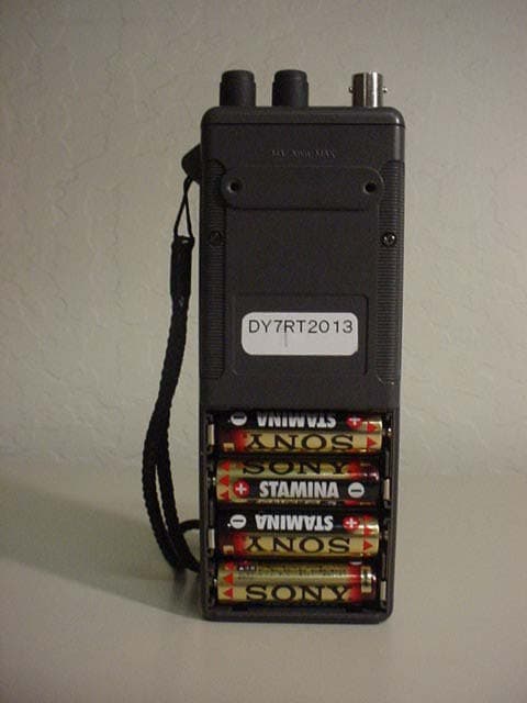
Click to zoom
Application Details
- Equipment Class
- CSR - Scanning Receiver
- Date of Grant
- Mar 03, 2003
- Application Purpose
- Original Equipment
- Date of Application
- Mar 03, 2003
- Equipment Note
- Scanning Receiver
- Frequency Range
- 118.00000000 - 143.00000000
- Company
- Sportsman's Market Inc
- Country
- United States
Documents & Files
Document Text
Text extracted from the exhibit documents filed with the FCC. Open a document above to read the original.
Users Manual
DY7RT2013 1 SP-125 OPERATION MANUAL Draft Ver 1.1 2003/02/27 DY7RT2013 2 SP-125 OPERATION MANUAL Table of contents THE FCC WANTS YOU TO KNOW --------------------------------------3 1. Functional Description of Each Operation Part --------------------------------------4 2. Key-Operation Summary --------------------------------------6 3. Direct Frequency Selection Operation --------------------------------------7 (1) Change operation of BAND --------------------------------------7 (2) The setup of the frequency by the numeric key --------------------------------------8 The received frequency setting in AIR BAND --------------------------------------8 The received frequency setting in AM BAND --------------------------------------9 The received frequency setting in FM BAND --------------------------------------10 (3) The setup of the frequency by UP key and DWN key--------------------------------------10 4. Channel and Memory Operation of AIR BAND -------------------------------------12 (1) The registration method to memory -------------------------------------12 (2) The method to call the channel which made memory------------------------------------13 (3) The erasure method of the channel which made memory-------------------------------13 (4) The package erasure method of the channel which made memory-------------------13 5. Priority Receiving -------------------------------------14 (1) Start and release of the priority receiving ----------------------------------------14 DY7RT2013 3 THE FCC WANTS YOU TO KNOW This equipment has been tested and found to comply with the limits for a scanning receiver, pursuant to Part 15 of the FCC Rules. These limits are designed to provide reasonable protection against harmful interference in a residential installation.This equipment generates, uses and can radiate radio frequency energy and, if not installed and used in accordance with the instructions, may cause harmful interference to radio communications. However, there is no guarantee that interference will not occur in a particular installation.if this equipment does cause harmful interference to radio or television reception, which can be determined by turning the equipment off and on, the user is encouraged to try to correct the interference by one or more of the following measures: 1) Reorient or relocate the receiving antenna. 2) Increase the separation between the equipment and receiver. 3) Connect the equipment into an outlet on a circuit different from that to the receiver is connected. This device complies with Part 15 of the FCC Rules. Operation is subject to the following two conditions: 1) This device may not cause harmful interference. 2) This device must accept any interference received, including interference that may cause undesired operation. Scanning Legally Your receiver covers frequencies used by some different groups including Aircraft communications and Military operations, Space-operation, Meteorological-Satellite,Space research,Mobile- satellite.It is legal to listen to almost every transmission your receiver can receive, However, there are some transmissions you should never intentionally listen to.These include: 1) Telephone conversations (private means of telephone signal transmission) 2) Any scrambled or encrypted transmissions. According to the Electronic Communications Privacy Act (ECPA), you are subject to fines and possible imprisonment for intentionally listening to, using, or divulging the contents of such a transmission unless you have the consent of a party to the communication (unless such activity is otherwise illegal). This receiver has been designed to prevent reception of illegal transmissions. This is done to comply with the legal requirement that receivers be manufactured so as to not be easily modifiable to pickup those transmissions. Do not open your receiver's case to make any modifications that could allow it to pick-up transmissions that it is not legal to listen to. Doing so could subject you to legal penalties. We encourage responsible, legal receiver use. Mobile use of this receiver is unlawful or requires a permit in some areas. Check the laws in your area. DY7RT2013 4 1. Functional Description of Each Operation Part. The functional description of each operation part is explained in the following. (1) ANT; Antenna terminal Use which installs the attached antenna. (2) EAR; Earphone jack The jack in the case of using the external loudspeaker or the earphone. (3) KEYLOCK; Key Lock button Each time it pushes KEYLOCK button, the effective of the keyboard grabbing and the invalid are changed. In the condition of having made the keylock, the display of "KEY.L" is made to the display and all the key operations on the keyboard become invalid. Again, KEY LOCK is canceled by pushing this button. (4) SQ; Squelch volume The volume for squelch sensitivity adjustment. Only AIR band receiving is available. (5) VOL; Power Switch & Audio Volume The function of the power switch and the sound-volume adjustment volume is made serve a double purpose. (6) External-power jack; EXT.Power Jack The jack in the case of using a power adapter (7) LCD display; LCD Disply The band during receiving or a frequency, a mode of operation, etc. are displayed. (8) Keyboard; Key Board For the input in the case of making the change of the band, and the selection of the frequency and the change of the mode of operation. Please refer to Chapter 2 for details. DY7RT2013 5 ANTENNA terminal KEY LOC K BOTTUN POWER SWITCH & VOLUME Squelch Volume External loudspeake r keyboard LCD display External-pow er terminal Fig. -1The SP-125 operation part DY7RT2013 6 2. Key-Operation Summary (1) Numerical keypad (0 to 9 key); Please input the received frequency. (2) MEM.CLR (0 key); Memory Clear Please use it for the erasure of the channel memory of AIR band. (3) PRIORITY (2 keys); Priority Please use it for execution and the cancellation of the priority scan. (4) LIGHT (3 keys); Light Please use it for ligh…
Text truncated - open the document above for the full version.
Attestation Statements
DY7RT2013 Sec. 15.121 Scanning receivers and frequency converters used with scanning receivers. Reference: Sporty's Model SP-125, FCC ill: DY7RT2013: This is to clarify that the above equipment is incapable of operating (tuning) or readily being altered by the user to operate, within the frequency bands to the Cellular Radio telephone Service. The frequencies in question are deleted from the ROM during manufacture, and cannot be restored through any readily available process or component such as: installation of cuts, jumper wires, resistors, diodes,or plug-in IC's;deletion of such items;or reprogramming via access codes or external devices such as a personal computer. The receiver is incapable of converting digital cellular transmissions to analog voice audio. Assessing the vulnerability of the receiver to possible modification The receiver has the possibility of reducing the threshold value to discern transmissions from the Cellular Radiotelephone Service by making modification such as adding jumper wire to the UHF RF tuning circuit and UHF mixer circuit. Design features that prevent modification of the receiver to receive Cellular Service The scanning receiver is designed to prevent any attempt for the user to modify the receiver to receive transmissions from the Cellular Radiotelephone Service by using epoxy to cover the required parts of the UHF RF tuning circuit. Testing method used to determine compliance with the 38 dB rejection ratio The scanning receiver prevents transmissions more than 38 dB from the Cellular Radiotelephone Service from being received for the following reasons: 1. The image frequencies in the frequency range from 0.53 MHz to 1.63 MHz are shown as follows: FR = 0.53 to 1.63 MHz IF=0.45MHz FR+2:xlF=IMAGE FREQ. (.53 to 1.63)+(2xO.45) = 1.43MHz to 2.53MHz IMAGE FREQ. These image frequencies are not included within the Cellular Radiotelephone Service Frequency Band. 1 DY7RT2013 2. The image frequencies in the frequency range from 88 to 107.2 MHz, shown as follows: FR=88 to 107.2MHz IF=10.7MHz FR+2xIF=IMAGE FREQ. (88 to 107.2)+(2xl0.7)=109.4 to 128.6MHz lMAGEFREQ, These image frequencies are not included within the Cellular Radiotelephone Service Frequency Band. 3. The image frequencies in the frequency range from 107.3 to 108 MHz, shown as follows: FR=107.3 to 108MHz IF=10.7MHz FR-2xIF=IMAGE FREQ. (88to 107 .2)-(2x10. 7)=85.9 to 86.6MHz .--lMAGEFREQ. These image frequencies are not included within the Cellular Radiotelephone Service Frequency Band. 4. The image frequencies in the frequency range from 118 to 142.975 MHz, shown as follows: FR=118 to 142.975MHz IF=21.4MHz FR+2xIF=IMAGE FREQ. (I18 to 142.975)+(2x21.4)=160.8 to 185.775MHz IMAGEFREQ. These image frequencies are not included within the Cellular Radiotelephone Service Frequency Band. 2 DY7RT2013 The 12 dB SINAD measurement method in the Cellular Radiotelephone Service used for frequencies that the receiver tunes and the signal rejection ratio gained by the measurement. Measurement method Tune the receiver to the received frequency and output the receiving frequency from SG to obtain its 12 dB SINAD. Then output the interference frequency to obtain its 12 dB SINAD. The signal rejection ratio is the ratio between these two SSG output levels. Test Results 1 Frequency range i (MHz) 118.000 Cellular frequency range included ; (MHz) , , 857.800 Received frequency (MHz) 118.000 119.000 120.000 121.000 122.000 123.000 124.000 Signal rejection ratio (dB) Equation for interference frequency reception (MHz) Interference frequency (MHz) 857.800 863.800 869.800 875.800 881.800 887.800 893.800 (FR+IF)*6+IF= 857.800 (FR+IF)*6+IF= 863.800 (FR+IF)*6+IF= 869.800 (FR+IF)*6+IF= 875.800 (FR+IF)*6+IF= 881.800 (FR+IF)*6+IF= 887.800 (FR+IF)*6+IF= 893.800 (FR+IF)*5+IF= 823.400 (FR+IF)*5+IF= 828.400 (FR+IF)*5+IF= 833.400 (FR+IF)*5+IF= 838.400 (FR+IF)*5+IF= 843.400 toto 124.000 139.000 893.800 823.400139.000 140.000 141.000 142.000 143.000 823.400 828.400 833.400 838.400 843.400 89 110 94 92 94 94 94 82 86 90 90 .22.. 86 110 110 98 90 90 90 90 90 90 84 86 90 toto 143.000 119.000 843.400 821.000119.000 120.000 121.000 122.000 123.000 124.000 125.000 126.000 127.000 128.000 129.000 130.000 131.000 821.000 827.000 833.000 839.000 845.000 851.000 857.000 863.000 869.000 875.000 881.000 887.000 893.000 (FR+IF)*6-IF= 821.000 (FR+IF)*6-IF= 827.000 (FR+IF)*6-IF= 833.000 (FR+IF)*6-IF= 839.000 (FR+IF)*6-IF= 845.000 (FR+IF)*6-IF= 851.000 (FR+IF)*6-IF= 857.000 (FR+IF)*6-IF= 863.000 (FR+IF)*6-IF= 869.000 (FR+IF)*6-IF= 875.000 (FR+IF)*6-IF= 881.000 (FR+IF)*6-IF= 887.000 (FR+IF~6-IF= 893.000 toto 131.000893.000 FR = received frequency IF=21.4MHz 3 DY7RT2013 Test Results 2 Cellular frequency range included (MHz) 824.710 to 893.310 Received frequency (MHz) 0.5301 Interference frequency ! 1(MHz) Signal rejection ratio (dB) Equation for interference frequency reception (MHz) (FR+IF)*842-IF= 824.710 I frequency range (MHz) 0.530 824.710 to 893.310 824.220 to , 893.070 110 .-!~-, 1.080 824.220 to 893.070 825.310 to 893.950 1.080 110 to 1.630 1.630 825.310 to 893.950 824.630 to 893.230 823.590 to 893.970 824.130 to 892.770 110 ~0.530824.630 to 893.230 0.530 110 (EB!LF)*Q11-IF= 893.230 to 1.080 823.590 to 893.970 1.080 (FR+IF)*538-IF= 823.590 110 (FR+IF~584-IF= 893.970 to 1.630824.130 to 892.770 1.630 (FR+IF)*396-IF= 824.130 110 (FR+IF)*429-IF= 892.770 = received frequency IF= 0.45MHz Test Results 3 Frequency range (MHz) ! Cellular ! frequency range included (MHz) Received frequency (MHz) Interference frequency (MHz) Signal rejection ratio (dB) Equation for interference frequency reception i (MHz) I (FR+IF)*8+IF= 824.300 i (FR+IF)*8+IF= 832.300 (FR+IF)*8+IF= 840.300 (FR+IF)*8+IF= 848.300 (FR+IF)*8+IF= 856.300 (FR+IF)*8+IF= 864.300 (FR+IF)*8+IF= 872.300 (FR+IF)*8+IF= 880.300 (FR+IF)*8+IF= 888.300 (FR+IF)*8+IF= 893.900 ; (FR+IF)*7+IF= 824.100 (FR+IF)*7+IF= 827.600 : (FR+IF)*7+IF= 834.600 (FR+IF)*7+IF= 836.000 I (FR-IF)*9+IF= 880.100 91.000 824.300 91.000 92…
Text truncated - open the document above for the full version.
External Photos
Equipment Photographs External – DY7RT2013 Equipment Photographs External – DY7RT2013 Equipment Photographs External – DY7RT2013 Equipment Photographs External – DY7RT2013 Equipment Photographs External – DY7RT2013 Equipment Photographs External – DY7RT2013
ID Label/Location Info
FCC NOTICE LABEL FCC ID ; DY7RT2013 This device complies with Part 15 of the FCC Rules. Operation is subject to the following two conditions:(1)This device may not cause harmful interference, and (2) this device must accept any interference received, including interference that may cause undersired operation. 40 15
Test Report
lntertek Testing Services ETL SEMKO TEST REPORT For SPORTSMAN'S MARKET, INC. Scanning Receiver Model: SP-125 FCC m: DY7RT2013 Job # 3036423 Report # 30364231 Date of Testing: December 26-27, 2002 Date of Report: December 29, 2002 Ilii:\ TI~ -J A2LA Certificate Nmnber: 1755-01 . ~lYJ\ ~\,..,0-J \I. ) Bruce Gordon, T <:- W"rnock H"",tv .i... FCC Part 15 Scanning Rx Cert enc -,- lr) ~ Intertek Testing Services NA, Inc. 1365 Adams Court, Menlo Park, CA 94025 Telephone 650-463-2900 Fax 650-463-2910 Home Page www.etlsemko.com 1365 Adams Court, Menlo Park, CA 94025 Sportsman’s Market, Inc., Model No: SP-125 FCC ID: DY7RT2013 Date of Test: December 26-27, 2002 Report #30364231 2 of 30 FCC Part 15 Scanning Rx Cert TABLE OF CONTENTS 1.0 General Description ........................................................................................................ 3 1.1 Product Description ........................................................................................................ 3 1.2 Related Submittal(s) Grants ............................................................................................ 3 1.3 Test Methodology ........................................................................................................... 3 1.4 Test Facility .................................................................................................................... 3 1.5 Summary of Test Results ................................................................................................ 4 2.0 System Test Configuration............................................................................................. 5 2.1 Justification ..................................................................................................................... 5 2.2 EUT Exercising Software ............................................................................................... 5 2.3 Mode of Operation.......................................................................................................... 5 2.4 Support Equipment List and Description........................................................................ 6 2.5 Equipment Setup Block Diagram ................................................................................... 6 2.6 Equipment Modification ................................................................................................. 6 3.0 Emission Test Results ..................................................................................................... 7 3.1 Field Strength Calculation .............................................................................................. 8 3.2 Radiated Emission Data .................................................................................................. 9 3.3 AC Line Conducted Emission Data .............................................................................. 14 3.4 Antenna Conducted Emission Data .............................................................................. 18 4.0 List of Test Equipment ................................................................................................. 25 5.0 Appendix A .................................................................................................................... 26 1365 Adams Court, Menlo Park, CA 94025 Sportsman’s Market, Inc., Model No: SP-125 FCC ID: DY7RT2013 Date of Test: December 26-27, 2002 Report #30364231 3 of 30 FCC Part 15 Scanning Rx Cert 1.0 General Description 1.1 Product Description The Sportsman’s Market, Inc, Model No.: SP-125 is a VHF Aircraft/AM/FM Broadcast Band Programmable Handheld Scanning Receiver. Please refer to the attached specifications sheets in Appendix A for more details. A pre-production version of the sample was received on December 25, 2002 in good condition. As declared by the Applicant, it is identical to production units. 1.2 Related Submittal(s) Grants This is a single Application for Certification of a scanning receiver. 1.3 Test Methodology Both AC mains line-conducted (if applicable) and radiated emission measurements were performed according to the procedures in ANSI C63.4 (1992). All radiated measurements were performed in a semi- anechoic chamber. Radiated tests were performed at an antenna to EUT distance of 3 meters, unless stated otherwise in the “Data Section” of this Application. 1.4 Test Facility The test site and conducted measurement facility used to collect the radiated data is Site 1 (10-m semi- anechoic chamber). This test facility and site measurement data have been fully placed on file with the FCC and A2LA accredited. 1365 Adams Court, Menlo Park, CA 94025 Sportsman’s Market, Inc., Model No: SP-125 FCC ID: DY7RT2013 Date of Test: December 26-27, 2002 Report #30364231 4 of 30 FCC Part 15 Scanning Rx Cert 1.5 Summary of Test Results Model: SP-125 FCC ID: DY7RT2013 TEST REFERENCE RESULTS Radiated Emission 15.109 Complies AC Lie Conducted Emission 15.107 Complies Antenna Conducted Emission 15.111 Complies FCC Part 15. 121 Requirement 15.121 Complies * * See File “FCC 15.121” 1365 Adams Court, Menlo Park, CA 94025 Sportsman’s Market, Inc., Model No: SP-125 FCC ID: DY7RT2013 Date of Test: December 26-27, 2002 Report #30364231 5 of 30 FCC Part 15 Scanning Rx Cert 2.0 System Test Configuration 2.1 Justification The tests were performed according to the test procedure as outlined in CFR47 Part 15.31 and in ANSI C63.4. For emission testing, the equipment under test (EUT) was configured for testing in a typical fashion (as a customer would normally use it). During testing, all cables were manipulated to produce worst-case emissions. For the measurements, the EUT is placed on top of a non-conductive table. If the EUT attaches to peripherals, they are connected and operational (as typical as possible). For radiated emission measurements, the signal is maximized through rotation and placement in the three orthogonal axes. The antenna height and polarization are varied during the sear…
Text truncated - open the document above for the full version.
Test Setup Photos
Test Setup Photos DY7RT2013 Radiated Emissions Test Setup Photos DY7RT2013 Radiated Emissions Test Setup Photos DY7RT2013 Radiated Emissions Test Setup Photos DY7RT2013 Radiated Emissions Test Setup Photos DY7RT2013 Radiated Emissions Test Setup Photos DY7RT2013 Radiated Emissions Test Setup Photos DY7RT2013 Radiated Emissions Test Setup Photos DY7RT2013 Radiated Emissions Test Setup Photos DY7RT2013 Radiated Emissions Test Setup Photos DY7RT2013 AC Line Conducted Test Setup Photos DY7RT2013 AC Line Conducted
Contact Information
Applicant
Rod Hoskins
Technical Contact
Intertek Testing ServicesDavid Chernomordik
[email protected]650 463 2900
1365 Adams Court · Menlo Park, California · United States
Non-Technical Contact
Intertek Testing ServicesDavid Chernomordik
[email protected]650 463 2900
Test Firm
Intertek Testing Services NA Inc.John Quigley
Technical Specifications
| # | Rule Parts | Frequency Range | Power Output |
|---|---|---|---|
| 3 | 15B | 118 MHz - 143 MHz | - |
Other Applications from Sportsman's Market Inc
DY7J96012-A
Dec 16, 1997CSR - Scanning Receiver
Equipment Class
CSR - Scanning ReceiverDY7J96012
May 20, 1997CSR - Scanning Receiver
Equipment Class
CSR - Scanning ReceiverDY7J93021
Oct 23, 1995TNF - Licensed Non-Broadcast Transmitter Held to Face
Equipment Class
TNF - Licensed Non-Broadcast Transmitter Held to FaceDY79VI757
Jul 15, 1984CMB - Unkown (From ALTOS)
Equipment Class
CMB - Unkown (From ALTOS)