Text extracted from the exhibit documents filed with the FCC. Open a document above to read the original.
FUJI XEROX HFD2 User’s Manual This manual explains the installation process and function and performance of Radio Frequency Identification system (HFD2). This product does not permit a repair and an exchange by the end user. Please contact our service office or a FX product handling Service Company when the exchange of the device is necessary due to the trouble and so on. Also, please read this manual to the end surely, and use a product properly before you install HFD2 in your machine. Introduction This product uses the radio wave of 13.56MHz (Inductive Loop System). Therefore, this product takes a regulation and /or law such as output of the RF power by each country and /or self-governing body. Some cases, the final product (e.g. printer) adapts to the law of each country, and type approval may be required. The following shall be kept to use a product for the safety. A cable and TAG shall use designation accessories. A cable and TAG shall use designation accessories. When a power supply cable is changed, the following condition will be kept: - Keep the range of rated current. - Set the length of the cable at less than 2.5m. Do not remodel and/or dismantle this product. Don’t remodel this product because a Fire, Electric shock and Machine trouble may be caused. Because this product uses a radio wave, law of the country may punish for remodeling of the product. Shut off the power immediately when you notice smoke or unusual smell. Shut off the power (take off the power cable) immediately when you notice smoke or unusual smell, because it short-circuits, and a fire and an electric shock may be caused. Don’t put wiring and/or other articles on this product. This product builds in the antenna that radiates the radio wave. Performance may not be able to be maintained when the wire etc. is installed on the product and so on. Don’t install this product in the place to have the possibility for a liquid and other material fall. You may be struck by electricity or product may short-circuit. This product should be protected from any electrostatic discharge. This product may be damaged by the static electricity that accumulated in the human body and so on. Connect a human body to the ground at the time of the maintenance or discharge before the work. Product use environment is keeping the following. Operating temperature: +5 °C to +55°C Storage temperature: -30°C to 75 °C Humidity: 5% to 85% non-condensing Voltage Tolerance: DC +5V +/-10% How to scrap this product Make contact with Fuji Xerox or our company agency when you scrap this product. Or, follow ordinances such as each country and a local government. Please ask each county and a self-governing body about the information of the regulations. Notice about the law and the standard CE 0682 This product applies the European NB certificate where it followed the 99/5/ EEC. An applicable standard is as follows; EN 300 330 V1.3.2 EN 301 489 -1 and EN 301 489 -3 FCC ID: E46HFD2, IC:xxxx-xxxx This device complies with Part 15 of the FCC Rules. Operation is subject to the following two conditions: (1) this device may not cause harmful interference, and (2) this device must accept any interference received, including interference that may cause undesired operation. This product acquires the certification or approval of the wireless module. However, a product (e.g. printer) that contains this module must apply the various standards required to the product. Outline of the product Summary HFD2 Unit System is RFID (Radio Frequency Identification) device for an Inductive loop coupling. This system has two modules of the Reader/Writer (HFD2-C) and Tag (HFD1-T). - HFD2 generates a 13.56MHz signal on internal looped antenna. - Transmitted data are modulated using Amplitude Shift Keying (ASK) modulation. - Received data are demodulated from the Tag load variation signal, generated on the antenna. - Tag is battery less memory with a looped antenna. - Communication distance between HFD2-C and HFD1-T is 3mm to 10mm. Block diagram of the product OSCASK Modulation BPF Amp Antenna 12x27mm ASK Demodulatio Data Control ASIC 13.56MHz 2SC1621 BPF Buffer MUTE TXDATA CRRD ASK Modulation BPF Antenna 12x27mm 2SC1621 SEL TX Cont. TX Cont. TX Enable TX Data RX Data Select System Requirement The following condition shall be kept, that use HFD2 unit system. - HFD2 must be used with the HFD1-T. - HFD2 must be internally installed in machine. (e.g. Printer, Copy machine etc.) - I/F Cable length (including DC power cable) must be 2.5m or less. - Supply DC Voltage must be 5V+/- 10%. - The certification label and/or the notice of the manual may be necessary for the final product enclosure, which contains this unit. Specifications The specifications of the product are as the following; - Carrier Frequency: 13.56MHz +/- 100ppm - Modulation: 106Kbps ASK - Communication distance: 3mm to 10mm (It means the distance of the Reader Writer Module ANT and Tag Module ANT.) - Supply Voltage: DC 5V +/- 10% - Rated current: 100mA - Signal Level: TTL (3.3V) - Operating temperature: +5 °C to +55°C - Maximum RF power: 7mW (Fixed for maximum power) Layout of the module Installation example The example used for the toner cartridge sensor of the printer is shown in the following. HFD2-C is not visible from the outside after attachment. Because, HFD2-C is covered with a plastic cover. Instillation of module to the copy machine ASK modulation (For left side antenna) Oscillation circuit (Common) ASK demodulation (Common) Antenna selection The arrangement target mark of TAG ASK modulation (For right side antenna) The arrangement target mark of TAG Loop Antenna (Left) HFD2-C Loop Antenna (Right) PWBA CPL2 FX HFD2-C CE0462 ! FCCID=E046HFD2 160M95840 K 0.1 To n e r cartridge HFD2-C Installation of TAG to the toner cartridge The explanation of the test mode Following the explanation about the continuous radiation and stand-by mode used for the test. Continuous Radiation Mode (Maximum radiation power) Only a lefts…
Text truncated - open the document above for the full version.
August 24, 2003 CONFIDENTIALITY REQUEST Federal Communications Commission Authorization and Evaluation Division 7435 Oakland Mills Road Columbia, MD 21046 Re: Fuji Xerox Co., Ltd. application for Low Power Communications Device FCC ID:E46FHD2 Gentlemen: Fuji Xerox Co., Ltd, 7-1, 2274 Hongo,Ebina-shi, Kanagawa 243-0494, Japan herein submits an Application for Equipment Authorization for certification of a spread spectrum transmitter under FCC Rules Part 15. Fuji Xerox Co., Ltd., requests, pursuant to 47CFR 0.459, post grant confidentiality for portions of the material contained in this application such that the identified material will be withheld from public inspection following the grant of this authorization. This material, as indicated by request for confidentiality of the item during the electronic submission process and further identified below, includes: 1. Circuit diagrams submitted as attachment: "schematics”. 2. Block diagram submitted as attachment “block diagram”. 3. Theory of operation submitted as attachment “operational description”. 4. Parts list submitted as attachment “parts list”. Specifically, these exhibits contain information relating to circuit function and complexity that could be of benefit to competitors. The material contains trade secrets and confidential information that Fuji Xerox does not customarily release to the public and which is otherwise not generally available to the public. Please contact the undersigned by phone at 410-531-3439, by fax at 410-531-0807, by email at [email protected], or by correspondence at the address below if there are any further questions or additional information needed concerning this filing. Regards, (signed) Phillip Inglis, TRP/Cetecom b.v.b.a. 14085 Howard Rd. Dayton, MD. 21036
August 24, 2003 14085 Howard Rd Dayton, MD 21036 Federal Communications Commission 7435 Oakland Mills Road Columbia, MD 21036 Re: FCC ID:E46HFD2 Gentlemen: Submitted herewith is an application for a low frequency transmitter module containing dual 13.56 MHz RF output antenna assemblies to be used in a series of printer/copier products having essentially the same form factor. In accordance with the requirements set forth in DA 00-1407 Released: June 26, 2000, this device incorporates the design features as described and listed below for Part 15 limited modular transmitter approval: 1. The modular transmitter has its own RF shielding to the extent needed. As can be seen from the test site photos, the device was tested outside the host equipment that provided data and power to the unit. The RF transmitter module is used across many printers comprising a family of products having the same basic mechanical and electrical specifications. 2. This modular transmitter only has data inputs inductively coupled via the toner cartridge transponder assembly thus ensuring that the module will continue to comply with Part 15 requirements and no conditions of excessive data rates or over-modulation can occur. 3. This modular transmitter receives its DC power from a regulated supply providing power to the main PC board and has an on board regulator as well. The design of the power supply circuitry in the printers into which the PC board is installed requires a regulated supply voltage at a fixed level to the PC board thus ensuring the modular transmitter will always receive the correct regulated voltage. 4. The modular transmitter complies with the antenna requirements of Section 15.203 and 15.204(c) and is a small multi-turn inductively coupled loop antenna that couples to the toner cartridge transponder. 5. This modular transmitter was tested in a stand-alone configuration outside the host device during testing. The host device is an ac-powered unit intended to be used as an office/business printer. No modifications were made to the host device. 6. This modular transmitter is labeled with its own FCC ID number, and, if the FCC ID is not visible when the module is installed inside another device, then the outside of the device into which the module is installed will also display a label referring to the enclosed module. This exterior label will use this wording: “Contains FCC ID: E46HFD2”. 7. This modular transmitter complies with all operating requirements applicable to the transmitter. 8. This modular transmitter complies with applicable RF exposure requirements. Its measured field strength level is 29.4dB uV/m at 10 meters. Further, the module is intended to be installed inside a host device which provides additional isolation from the user. Specific installation and operating instructions for users are not required as the only user installed portion of this system is replacement toner cartridges that have very fixed installation procedures. If there are any additional questions, please contact me at 410-531-3439. Sincerely yours, Phillip Inglis TRP/Cetecom bvba
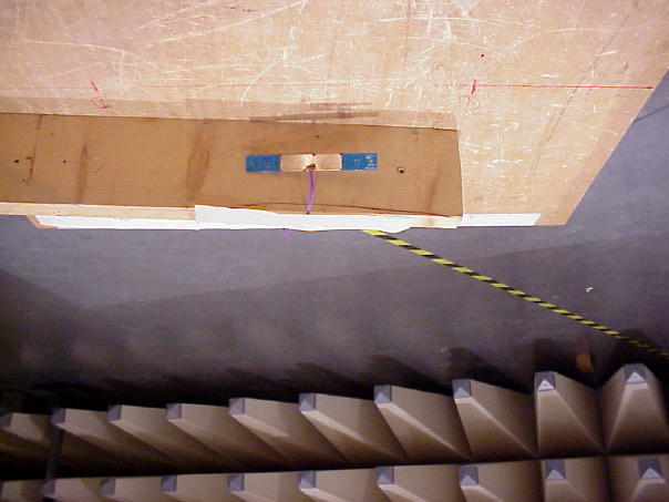
CETECOM ICT Services GmbH Test report no.: 2-3252-01-03/03Date: 2003.07.03Page 17 (22) PHOTOGRAPHS OF THE EQUIPMENT Photograph No.: 1
Label for FCC ID:E46HFD2. Due to the small size, the compliance label required by the rules is incorporated in the user’s manual. FCC ID:E46HFD2 Label for FCC ID: E46HFD2 to be placed on bottom of unit it is installed in with compliance statement. This devices contains FCC ID:E46HFD2 This device complies with Part 15 of the FCC Rules. Operation is subject to the following two conditions: (1) this device may not cause harmful interference, and (2) this device must accept any interference received, including interference that may cause undesired operation. Bottom of unit. Label Loc.
CETECOM ICT Services GmbH Test report no.: 2-3252-01-03/03Date: 2003.07.03Page 20 (22) Photograph No.: 5 CETECOM ICT Services GmbH Test report no.: 2-3252-01-03/03Date: 2003.07.03Page 21 (22) Photograph No.: 6 CETECOM ICT Services GmbH Test report no.: 2-3252-01-03/03Date: 2003.07.03Page 22 (22) Photograph No.: 7
CETECOM ICT Services GmbH Radio Satellite Communication Untertürkheimer Straße 6–10 , D-66117 Saarbrücken Telefon +49 (0) 681 598–0 , Fax –9075 Test report No.: 2-3252-01-04/03This test report consists of 20 pages Recognized by the Federal Communications Commission FCC–Identification Number: 90462 TCB ID: DE 0001 Accredited by the German Accreditation Council DAR–Registration Number TTI–P–G 166/98 Independent ETSI compliance test house ETSI Accredited Bluetooth™ Test Facility (BQTF) Testreport No.: 2_3252-01-04/03 Type: HFD 2 Applicant: FUJI XEROX FCC Part: 15.209 FCC ID : E46HFD2 CETECOM ICT Services GmbH Test report no.: 2-3252-01-04/03Date: 2003.07.03 Page 2 (22) Table of contents 1 General information 1.1 Notes 1.2 Testing laboratory 1.3 Details of applicant 1.4 Application details 1.5 Test item 1.6 Test specifications 2 Technical test 2.1 Summary of test results 2.2 Test report CETECOM ICT Services GmbH Test report no.: 2-3252-01-04/03Date: 2003.07.03 Page 3 (22) 1 General information 1.1 Notes The test results of this test report relate exclusively to the test item specified in 1.5. The CETECOM ICT Services GmbH does not assume responsibility for any conclusions and generalisations drawn from the test results with regard to other specimens or samples of the type of the equipment represented by the test item. The test report may only be reproduced or published in full. Reproduction or publication of extracts from the report requires the prior written approval of the CETECOM ICT Services GmbH. Test laboratory manager: 2003-07-03RSC - 8431Gillmann D. DateSectionNameSignature Technical responsibility for area of testing: 2003-07-03RSC - 8412Hausknecht D. DateSectionNameSignature CETECOM ICT Services GmbH Test report no.: 2-3252-01-04/03Date: 2003.07.03 Page 4 (22) 1.2 Testing laboratory CETECOM ICT Services GmbH Untertürkheimer Straße 6 - 10 66117 Saarbrücken Germany Telephone: + 49 681 598 - 0 Telefax : + 49 681 598 - 9075 E-mail: [email protected] Internet: www.cetecom-ict.de Accredited testing laboratory Accredited by: Regulierungsbehörde für Telekommunikation und Post (RegTP) Listed by: Federal Communications Commission (FCC) AuthorityIdentification/Registration No. RegTPTTI-P-G 166/98-30 FCC90462 1.3Details of applicant Name :FUJI XEROX CO., LTD Street :2274 Hongo,Ebina-shi City :Kanagawa 243-0494 Country :Japan Telephone:+81-46-238-3111 Telex :+81-46-238-5796 E-mail :[email protected] Contact person: Name : Mr. Tsuneo Imada Telephone:+81-46-238-3111 Telex :+81-46-238-5796 E-mail : : [email protected] 1.4Application details Date of receipt of test item : 2003-07-03 Date of test: 2003-0703 Person(s) who have been : Mr. G.Hedderich present during the test Mr. Masayuki Hirata CETECOM ICT Services GmbH Test report no.: 2-3252-01-04/03Date: 2003.07.03 Page 5 (22) CETECOM ICT Services GmbH Test report no.: 2-3252-01-04/03Date: 2003.07.03 Page 6 (22) 1.5Test item Type of equipment :Cartridge identification Type designation:HFD1(Part composition: HFD2-C, HFD1-T) Manufacturer:applicant Street: City: Country: Additional Information: Frequency:13.56 MHz ± 100 ppm Frequency (EUT):13.56 MHz Number of channels :1 Number of channels (EUT):1 Modulation:Tx : 0H00NON; Passiv transponder: 4K00F1D Antenna HFD 1 Integral ant.0,0032m² ERP:29.4dBμV/m Power supply (DC):5.0V Type of equipment :Class 1, Category III FCC IDE46HFD2 1.6Test specifications: FCC Part 15 §15.209 CANADA RSS-210 CETECOM ICT Services GmbH Test report no.: 2-3252-01-04/03Date: 2003.07.03 Page 7 (22) 2 Technical test 2.1 Summary of test results The radiated measurements are performed in vertical and horizontal plane in the frequency range from 9 kHz to 20 GHz in semi-anechoic chambers. The EUT is positioned on a non-conductive support with a height of 0.80 m above a conductive ground plane that covers the whole chamber. The receiving antennas are conform with specifications ANSI C63.2-1987 clause 15 and ANSI C63.4- 1992 clause 4.1.5. These antennas can be moved over the height range between 1.0 m and 4.0 m in order to search for maximum field strength emitted from EUT. The measurement distances between EUT and receiving antennas are indicated in the test set-ups for the various frequency ranges. For each measurement, the EUT is rotated in all three axes until the maximum field strength is received. The wanted and unwanted emissions are received by spectrum analysers where the detector modes and resolution bandwidths over various frequency ranges are set according to requirement ANSI C63-4-1992 clause 4.2. Antennas are conform with ANSI C63.2-1996 item 15. 150 kHz - 30 MHz: Quasi Peak measurement, 9kHz Bandwidth, passive loop antenna. 30 MHz - 200 MHz: Quasi Peak measurement, 120KHz Bandwidth, biconical antenna 200MHz - 1GHz: Quasi Peak measurement, 120KHz Bandwidth, log periodic antenna >1GHz: Average, RBW 1MHz, VBW 10 Hz, wave guide horn All measurement settings are according to FCC 15.35, 15.209. The product fulfils also the requirements for CANADA RSS-210 No deviations from the technical specification(s) were ascertained in the course of the tests performed. FINAL VERDICT : PASS CETECOM ICT Services GmbH Test report no.: 2-3252-01-04/03Date: 2003.07.03 Page 8 (22) LIST OF MEASUREMENTS. The list of measured parameters is given below. Clause Page number Transmitter parameters § 15.209Effective radiated RF power9 § 15.209Spurious radiations – Radiated10 Test equipment listing14 Plots of the equipment16 Photographs of the equipment16 CETECOM ICT Services GmbH Test report no.: 2-3252-01-03/03Date: 2003.07.03Page 9 (22) MAXIMUM PEAK OUTPUT POWER (RADIATED) TEST CONDITIONSMAXIMUM PEAK OUTPUT POWER (dBμV/m) @10m Frequency (MHz)13.56 MHz T nom ( 23 )?CV nom ( 5.0 )V 29.4 Maximum deviation from output power under extreme test conditions (dBc) not applicable Measurement uncertainty±3dB Limits SUBCLAUSE § 15.209 Frequency (MHz)Field strength (μV/m)Measurement distance (m) 0.009 – 0.4902400/F(kHz)300 0.490…
Text truncated - open the document above for the full version.
CETECOM ICT Services GmbH Test report no.: 2-3252-01-03/03Date: 2003.07.03Page 18 (22) Photograph No.: 2 CETECOM ICT Services GmbH Test report no.: 2-3252-01-03/03Date: 2003.07.03Page 19 (22) Photograph No.: 3
14085 Howard Rd · Dayton, Maryland · United States
| # | Rule Parts | Frequency Range | Power Output |
|---|---|---|---|
| 1 | 15C | 13.56 MHz - 13.56 MHz | - |

Transmitter module for use in printers.
Equipment Class
DXX - Part 15 Low Power Communication Device Transmitter
