E5M-LEDR400SLEDR Microwave Radio
GE MDS, LLC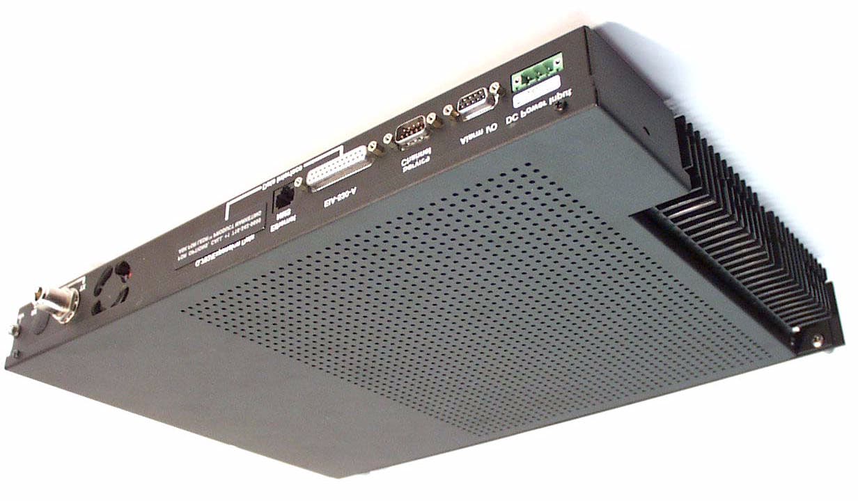
Click to zoom
Application Details
- Equipment Class
- TNB - Licensed Non-Broadcast Station Transmitter
- Date of Grant
- Nov 06, 2000
- Application Purpose
- Original Equipment
- Date of Application
- Sep 14, 2000
- Equipment Note
- LEDR Microwave Radio
- Frequency Range
- 406.12500000 - 512.00000000
- Company
- GE MDS, LLC
- Country
- United States
Documents & Files
Document Text
Text extracted from the exhibit documents filed with the FCC. Open a document above to read the original.
Users Manual
Installation and Operation Guide MDS 05-3627A01, Rev. A MARCH 2000 Digital Microwave Radio LEDR Subrate Series Covers LEDR 400S, 900S and 1400S (plus optional fractional interface) QUICK START GUIDE Below are the basic steps for installing the LEDR radio. When making cable connections, refer to page 10 for a rear panel view of the radio. 1. Install and connect the antenna system to the radio • Ensure a path study has been conducted and that the radio path is acceptable. • Use good quality, low loss coaxial cable. Keep the feedline as short as possible. • Preset directional antennas in the direction of desired transmission/reception. 2. Connect the data equipment to appropriate rear panel connector • For standard “S” Series radios, see Figure 25. • For radios equipped with an FT1 Option Board, see Figure 26. • Verify the data equipment is configured as DTE. (By default, the radio is configured as DCE.) 3. Apply DC power to the radio • Verify that the voltage matches the power supply operating range (24 Vdc or 48 Vdc). • The power connector is a three-pin keyed connector. The power source can be connected with either polarity. The center conductor is not connected. 4. Set the radio’s basic configuration using front panel or Console interface • You must first login with a valid username and password (see page 16). • Set the transmit/receive frequencies ( TX xxx.xxxx / RX xxx.xxxx ). • Refer to this manual for other configuration settings. 5. Verify proper operation by observing the LED display • Refer to “LEDs” on page 19 for a description of the status LEDs. • Aim directional antenna for maximum receive signal strength using the RSSI Screen. 6. Configure the Simple Network Management Protocol (SNMP) MIB, if used • Refer to the SNMP Handbook (Part No. 05-3532A01). MDS 05-3627A01, Rev. ALEDR “S” Series I/O Guidei TABLE OF CONTENTS 1.0 INTRODUCTION ......................................................................... 1 1.1 Product Description .......................................................................... 1 LEDR Features............................................................................... 1 Typical Applications ........................................................................ 2 1.2 Model Number Codes ...................................................................... 3 2.0 INSTALLATION ............................................................................ 4 2.1 General Requirements ..................................................................... 4 Site Selection ................................................................................. 5 Terrain and Signal Strength............................................................ 5 On-the-Air Test ............................................................................... 6 A Word About Interference ............................................................. 6 2.2 Antenna and Feedline Selection ...................................................... 7 Antennas ........................................................................................ 7 Feedlines ........................................................................................ 8 2.3 Radio Mounting ................................................................................ 9 Attaching the Rack Brackets ........................................................ 10 2.4 Radio Rear Panel Connectors ....................................................... 10 Ground Stud ................................................................................. 11 Antenna/TX .................................................................................. 11 RX ................................................................................................ 11 G.703 Data Connectors (4)—For radios with FT1 Option Bd....... 11 Ethernet........................................................................................ 11 EIA-530-A..................................................................................... 12 Service Channel ........................................................................... 12 Alarm I/O ...................................................................................... 12 Power ........................................................................................... 12 2.5 Protected Switch Rear Panel Connectors ...................................... 12 RxA............................................................................................... 13 RxB............................................................................................... 13 Antenna ........................................................................................ 13 TxA ............................................................................................... 13 TxB ............................................................................................... 13 Protected Data ............................................................................. 13 E1 ................................................................................................. 13 Ethernet........................................................................................ 14 530 (A&B)..................................................................................... 14 EIA-530-A..................................................................................... 14 Service Channel ........................................................................... 14 2.6 Inter-Unit Cabling for Protected Stations ........................................ 14 3.0 OPERATION .............................................................................. 15 iiLEDR “S” Series I/O GuideMDS 05-3627A01, Rev. A 3.1 Initial Startup .................................................................................. 15 Maximizing RSSI .......................................................................... 16 Initial Login—Required to change radi…
Text truncated - open the document above for the full version.
Users Manual
Product Notes1 of 1 PRODUCT NOTES JULY 2000 LEDR 400S Microwave Radio Microwave Data Systems Inc., 175 Science Parkway, Rochester, NY 14620 USA Phone +1 (716) 242-9600 • FAX +1 (716) 242-9620 • www.microwavedata.com FCC Part 15 Notice (Applies to LEDR 400S Models) NOTE: This equipment has been tested and found to comply with the limits for a Class A digital device, pursuant to Part 15 of the FCC Rules. These limits are designed to provide reasonable protection against harmful interference when the equipment is operated in a commercial environment. This equipment generates, uses, and can radiate radio frequency energy and, if not installed and used in accordance with the instruction manual, may cause harmful interference to radio communications. Operation of this equipment in a residential area is likely to cause harmful interference in which case the user will be required to correct the interference at his own expense. WARNING: Changes or modifications not expressly approved by manufacturer could void the user’s authority to operate the equipment.
Users Manual
Installation and Operation Guide MDS 05-3627A01, Rev. A MARCH 2000 Digital Microwave Radio LEDR Subrate Series Covers LEDR 400S, 900S and 1400S (plus optional fractional interface) QUICK START GUIDE Below are the basic steps for installing the LEDR radio. When making cable connections, refer to page 10 for a rear panel view of the radio. 1. Install and connect the antenna system to the radio • Ensure a path study has been conducted and that the radio path is acceptable. • Use good quality, low loss coaxial cable. Keep the feedline as short as possible. • Preset directional antennas in the direction of desired transmission/reception. 2. Connect the data equipment to appropriate rear panel connector • For standard “S” Series radios, see Figure 25. • For radios equipped with an FT1 Option Board, see Figure 26. • Verify the data equipment is configured as DTE. (By default, the radio is configured as DCE.) 3. Apply DC power to the radio • Verify that the voltage matches the power supply operating range (24 Vdc or 48 Vdc). • The power connector is a three-pin keyed connector. The power source can be connected with either polarity. The center conductor is not connected. 4. Set the radio’s basic configuration using front panel or Console interface • You must first login with a valid username and password (see page 16). • Set the transmit/receive frequencies ( TX xxx.xxxx / RX xxx.xxxx ). • Refer to this manual for other configuration settings. 5. Verify proper operation by observing the LED display • Refer to “LEDs” on page 19 for a description of the status LEDs. • Aim directional antenna for maximum receive signal strength using the RSSI Screen. 6. Configure the Simple Network Management Protocol (SNMP) MIB, if used • Refer to the SNMP Handbook (Part No. 05-3532A01). MDS 05-3627A01, Rev. ALEDR “S” Series I/O Guidei TABLE OF CONTENTS 1.0 INTRODUCTION ......................................................................... 1 1.1 Product Description .......................................................................... 1 LEDR Features............................................................................... 1 Typical Applications ........................................................................ 2 1.2 Model Number Codes ...................................................................... 3 2.0 INSTALLATION ............................................................................ 4 2.1 General Requirements ..................................................................... 4 Site Selection ................................................................................. 5 Terrain and Signal Strength............................................................ 5 On-the-Air Test ............................................................................... 6 A Word About Interference ............................................................. 6 2.2 Antenna and Feedline Selection ...................................................... 7 Antennas ........................................................................................ 7 Feedlines ........................................................................................ 8 2.3 Radio Mounting ................................................................................ 9 Attaching the Rack Brackets ........................................................ 10 2.4 Radio Rear Panel Connectors ....................................................... 10 Ground Stud ................................................................................. 11 Antenna/TX .................................................................................. 11 RX ................................................................................................ 11 G.703 Data Connectors (4)—For radios with FT1 Option Bd....... 11 Ethernet........................................................................................ 11 EIA-530-A..................................................................................... 12 Service Channel ........................................................................... 12 Alarm I/O ...................................................................................... 12 Power ........................................................................................... 12 2.5 Protected Switch Rear Panel Connectors ...................................... 12 RxA............................................................................................... 13 RxB............................................................................................... 13 Antenna ........................................................................................ 13 TxA ............................................................................................... 13 TxB ............................................................................................... 13 Protected Data ............................................................................. 13 E1 ................................................................................................. 13 Ethernet........................................................................................ 14 530 (A&B)..................................................................................... 14 EIA-530-A..................................................................................... 14 Service Channel ........................................................................... 14 2.6 Inter-Unit Cabling for Protected Stations ........................................ 14 3.0 OPERATION .............................................................................. 15 iiLEDR “S” Series I/O GuideMDS 05-3627A01, Rev. A 3.1 Initial Startup .................................................................................. 15 Maximizing RSSI .......................................................................... 16 Initial Login—Required to change radi…
Text truncated - open the document above for the full version.
Users Manual
Product Notes1 of 1 PRODUCT NOTES JULY 2000 LEDR 400S Microwave Radio Microwave Data Systems Inc., 175 Science Parkway, Rochester, NY 14620 USA Phone +1 (716) 242-9600 • FAX +1 (716) 242-9620 • www.microwavedata.com FCC Part 15 Notice (Applies to LEDR 400S Models) NOTE: This equipment has been tested and found to comply with the limits for a Class A digital device, pursuant to Part 15 of the FCC Rules. These limits are designed to provide reasonable protection against harmful interference when the equipment is operated in a commercial environment. This equipment generates, uses, and can radiate radio frequency energy and, if not installed and used in accordance with the instruction manual, may cause harmful interference to radio communications. Operation of this equipment in a residential area is likely to cause harmful interference in which case the user will be required to correct the interference at his own expense. WARNING: Changes or modifications not expressly approved by manufacturer could void the user’s authority to operate the equipment.
Cover Letter(s)
September 5, 2000 FEDERAL COMMUNICATIONS COMMISSION 7435 Oakland Mills Road Columbia, MD 21046 USA Subject: Type Acceptance Application under FCC CFR 47, Parts 2 and 90 (Subpart I) - Radio Services Transmitters Operating in the frequency band 409 - 510 MHz (25 kHz Channel Spacing). Applicant: Microwave Data Systems Inc. Product: LEDR Microwave Radio Model: LEDR 400S FCC ID: E5M-LEDR400S Dear Sir/Madam, As appointed agent for Microwave Data Systems Inc., please find copy of the engineering report, authorization letter, confidential filing letter and all the necessary items pertaining to submission. Note that the user’s manual, test data plots and schematics bear the Adaptive Broadband company name, which was the former name of Microwave Data Systems Inc. If you have any queries, please do not hesitate to contact us by our TOLL FREE numbers: OUR TELEPHONE NO.: 1-877-765-4173 Yours truly, Tri Minh Luu, P. Eng., V.P., Engineering TML/AK Encl. 2 3000 Bristol Circle, Oakville, Ontario, Canada L6H 6G4 Telephone (905) 829-1570 Facsimile (905) 829-8050 Website: www.ultratech-labs.com Email: [email protected] UltraTech Group of Labs
Cover Letter(s)
September 5, 2000 FEDERAL COMMUNICATIONS COMMISSION 7435 Oakland Mills Road Columbia, MD 21046 USA Subject: Type Acceptance Application under FCC CFR 47, Parts 2 and 90 (Subpart I) - Radio Services Transmitters Operating in the frequency band 409 - 510 MHz (25 kHz Channel Spacing). Applicant: Microwave Data Systems Inc. Product: LEDR Microwave Radio Model: LEDR 400S FCC ID: E5M-LEDR400S Dear Sir/Madam, As appointed agent for Microwave Data Systems Inc., please find copy of the engineering report, authorization letter, confidential filing letter and all the necessary items pertaining to submission. Note that the user’s manual, test data plots and schematics bear the Adaptive Broadband company name, which was the former name of Microwave Data Systems Inc. If you have any queries, please do not hesitate to contact us by our TOLL FREE numbers: OUR TELEPHONE NO.: 1-877-765-4173 Yours truly, Tri Minh Luu, P. Eng., V.P., Engineering TML/AK Encl. 2 3000 Bristol Circle, Oakville, Ontario, Canada L6H 6G4 Telephone (905) 829-1570 Facsimile (905) 829-8050 Website: www.ultratech-labs.com Email: [email protected] UltraTech Group of Labs
External Photos
EXHIBIT 11 EXTERNAL EUT PHOTOS PHOTO 1 of 3 FCC ID: E5M-LEDR400S EXHIBIT 11 EXTERNAL EUT PHOTOS PHOTO 2 of 3 FCC ID: E5M-LEDR400S EXHIBIT 11 EXTERNAL EUT PHOTOS PHOTO 3 of 3 FCC ID: E5M-LEDR400S
Internal Photos
EXHIBIT 12 INTERNAL EUT PHOTOS PHOTO 1 of 8 FCC ID: E5M-LEDR400S EXHIBIT 12 INTERNAL EUT PHOTOS PHOTO 2 of 8 FCC ID: E5M-LEDR400S EXHIBIT 12 INTERNAL EUT PHOTOS PHOTO 3 of 8 FCC ID: E5M-LEDR400S EXHIBIT 12 INTERNAL EUT PHOTOS PHOTO 4 of 8 FCC ID: E5M-LEDR400S EXHIBIT 12 INTERNAL EUT PHOTOS PHOTO 5 of 8 FCC ID: E5M-LEDR400S EXHIBIT 12 INTERNAL EUT PHOTOS PHOTO 6 of 8 FCC ID: E5M-LEDR400S EXHIBIT 12 INTERNAL EUT PHOTOS PHOTO 7 of 8 FCC ID: E5M-LEDR400S EXHIBIT 12 INTERNAL EUT PHOTOS PHOTO 8 of 8 FCC ID: E5M-LEDR400S
Test Report
EXHIBIT 9 PLOT 1 OF 11 MEASUREMENT DATA PLOTS FCC ID: E5M-LEDR400S EXHIBIT 9 PLOT 2 OF 11 MEASUREMENT DATA PLOTS FCC ID: E5M-LEDR400S EXHIBIT 9 PLOT 3 OF 11 MEASUREMENT DATA PLOTS FCC ID: E5M-LEDR400S EXHIBIT 9 PLOT 4 OF 11 MEASUREMENT DATA PLOTS FCC ID: E5M-LEDR400S EXHIBIT 9 PLOT 5 OF 11 MEASUREMENT DATA PLOTS FCC ID: E5M-LEDR400S EXHIBIT 9 PLOT 6 OF 11 MEASUREMENT DATA PLOTS FCC ID: E5M-LEDR400S EXHIBIT 9 PLOT 7 OF 11 MEASUREMENT DATA PLOTS FCC ID: E5M-LEDR400S EXHIBIT 9 PLOT 8 OF 11 MEASUREMENT DATA PLOTS FCC ID: E5M-LEDR400S EXHIBIT 9 PLOT 9 OF 11 MEASUREMENT DATA PLOTS FCC ID: E5M-LEDR400S EXHIBIT 9 PLOT 10 OF 11 MEASUREMENT DATA PLOTS FCC ID: E5M-LEDR400S EXHIBIT 9 PLOT 11 OF 11 MEASUREMENT DATA PLOTS FCC ID: E5M-LEDR400S
Test Report
LEDR Microwave Radio Model No.: LEDR 400S FCC ID: E5M-LEDR400S Applicant: Microwave Data Systems Inc. 175 Science Parkway Rochester, New York USA, 14620 Tested in Accordance With Federal Communications Commission (FCC) CFR 47, PARTS 2 and 90 (Subpart I) UltraTech's File No.: MIC23-FTX This Test report is Issued under the Authority of Tri M. Luu, Professional Engineer, Vice President of Engineering UltraTech Group of Labs .................................................................. Date: ........................... Report Prepared by: Dan Huynh ................................................................... Tested by: Hung Trinh, EMI/RFI Technician .................................................................... Issued Date: September 5, 2000 Test Dates: April 25 – May 4, August 25, 2000 The results in this Test Report apply only to the sample(s) tested, and the sample tested is randomly selected. UltraTech 3000 Bristol Circle, Oakville, Ontario, Canada, L6H 6G4 Telephone (905) 829-1570 Facsimile (905) 829-8050 Website: www.ultratech-labs.com Email: [email protected] FCC PARTS 2 & 90, SUBPART I, RADIO SERVICES TRANSMITTERS Contents i LEDR Microwave Radio FCC ID: E5M-LEDR400S ULTRATECH GROUP OF LABS File #: MIC23-FTX 3000 Bristol Circle, Oakville, Ontario, Canada L6H 6G4 September 5, 2000 Tel. #: 905-829-1570, Fax. #: 905-829-8050, Email: [email protected] , Website: http://www.ultratech-labs.com • Assessed by ITI (UK) Competent Body, NVLAP (USA) Accreditation Body & ACA/AUSTEL (Australia) • Recognized/Listed by FCC (USA), Industry Canada (Canada) • All test results contained in this engineering test report are traceable to National Institute of Standards and Technology (NIST) TABLE OF CONTENTS EXHIBIT 1. SUBMITTAL CHECK LIST......................................................................................................................1 EXHIBIT 2. INTRODUCTION........................................................................................................................................2 2.1. SCOPE.......................................................................................................................................................................2 2.2. RELATED SUBMITAL(S)/GRANT(S)...............................................................................................................................2 2.3. NORMATIVE REFERENCES..................................................................................................................................2 EXHIBIT 3. PERFORMANCE ASSESSMENT.............................................................................................................3 3.1. CLIENT INFORMATION............................................................................................................................................3 3.2. EQUIPMENT UNDER TEST (EUT) INFORMATION....................................................................................................3 3.3. EUT’S TECHNICAL SPECIFICATIONS................................................................................................................4 3.4. LIST OF EUT’S PORTS.................................................................................................................................................4 EXHIBIT 4. EUT OPERATING CONDITIONS AND CONFIGURATIONS DURING TESTS..............................5 4.1. CLIMATE TEST CONDITIONS.........................................................................................................................................5 4.2. OPERATIONAL TEST CONDITIONS & ARRANGEMENT FOR TEST SIGNALS......................................................................5 EXHIBIT 5. SUMMARY OF TEST RESULTS..............................................................................................................6 5.1. LOCATION OF TESTS............................................................................................................................................6 5.2. APPLICABILITY & SUMMARY OF EMC EMISSION TEST RESULTS..........................................................................6 5.3. MODIFICATIONS INCORPORATED IN THE EUT FOR COMPLIANCE PURPOSES...................................................................6 EXHIBIT 6. MEASUREMENTS, EXAMINATIONS & TEST DATA FOR EMC EMISSIONS..............................7 6.1. TEST PROCEDURES.....................................................................................................................................................7 6.2. MEASUREMENT UNCERTAINTIES.................................................................................................................................7 6.3. MEASUREMENT EQUIPMENT USED:..............................................................................................................................7 6.4. ESSENTIAL/PRIMARY FUNCTIONS AS DECLARED BY THE MANUFACTURER:......................................7 6.5. RF POWER OUTPUT @ FCC 2.985 & 90.205...............................................................................................................8 6.5.1. Limits @ FCC 90.205........................................................................................................................................8 6.5.2. Method of Measurements...................................................................................................................................8 6.5.3. Test Equipment List............................................................................................................................................8 6.5.4. Test Arrangement...............................................................................................................................................8 6.5.5. Test Data...........................................................................................................................................................…
Text truncated - open the document above for the full version.
Test Report
LEDR Microwave Radio Model No.: LEDR 400S FCC ID: E5M-LEDR400S Applicant: Microwave Data Systems Inc. 175 Science Parkway Rochester, New York USA, 14620 Tested in Accordance With Federal Communications Commission (FCC) CFR 47, PARTS 2 and 90 (Subpart I) UltraTech's File No.: MIC23-FTX This Test report is Issued under the Authority of Tri M. Luu, Professional Engineer, Vice President of Engineering UltraTech Group of Labs .................................................................. Date: ........................... Report Prepared by: Dan Huynh ................................................................... Tested by: Hung Trinh, EMI/RFI Technician .................................................................... Issued Date: September 5, 2000 Test Dates: April 25 – May 4, August 25, 2000 The results in this Test Report apply only to the sample(s) tested, and the sample tested is randomly selected. UltraTech 3000 Bristol Circle, Oakville, Ontario, Canada, L6H 6G4 Telephone (905) 829-1570 Facsimile (905) 829-8050 Website: www.ultratech-labs.com Email: [email protected] FCC PARTS 2 & 90, SUBPART I, RADIO SERVICES TRANSMITTERS Contents i LEDR Microwave Radio FCC ID: E5M-LEDR400S ULTRATECH GROUP OF LABS File #: MIC23-FTX 3000 Bristol Circle, Oakville, Ontario, Canada L6H 6G4 September 5, 2000 Tel. #: 905-829-1570, Fax. #: 905-829-8050, Email: [email protected] , Website: http://www.ultratech-labs.com • Assessed by ITI (UK) Competent Body, NVLAP (USA) Accreditation Body & ACA/AUSTEL (Australia) • Recognized/Listed by FCC (USA), Industry Canada (Canada) • All test results contained in this engineering test report are traceable to National Institute of Standards and Technology (NIST) TABLE OF CONTENTS EXHIBIT 1. SUBMITTAL CHECK LIST......................................................................................................................1 EXHIBIT 2. INTRODUCTION........................................................................................................................................2 2.1. SCOPE.......................................................................................................................................................................2 2.2. RELATED SUBMITAL(S)/GRANT(S)...............................................................................................................................2 2.3. NORMATIVE REFERENCES..................................................................................................................................2 EXHIBIT 3. PERFORMANCE ASSESSMENT.............................................................................................................3 3.1. CLIENT INFORMATION............................................................................................................................................3 3.2. EQUIPMENT UNDER TEST (EUT) INFORMATION....................................................................................................3 3.3. EUT’S TECHNICAL SPECIFICATIONS................................................................................................................4 3.4. LIST OF EUT’S PORTS.................................................................................................................................................4 EXHIBIT 4. EUT OPERATING CONDITIONS AND CONFIGURATIONS DURING TESTS..............................5 4.1. CLIMATE TEST CONDITIONS.........................................................................................................................................5 4.2. OPERATIONAL TEST CONDITIONS & ARRANGEMENT FOR TEST SIGNALS......................................................................5 EXHIBIT 5. SUMMARY OF TEST RESULTS..............................................................................................................6 5.1. LOCATION OF TESTS............................................................................................................................................6 5.2. APPLICABILITY & SUMMARY OF EMC EMISSION TEST RESULTS..........................................................................6 5.3. MODIFICATIONS INCORPORATED IN THE EUT FOR COMPLIANCE PURPOSES...................................................................6 EXHIBIT 6. MEASUREMENTS, EXAMINATIONS & TEST DATA FOR EMC EMISSIONS..............................7 6.1. TEST PROCEDURES.....................................................................................................................................................7 6.2. MEASUREMENT UNCERTAINTIES.................................................................................................................................7 6.3. MEASUREMENT EQUIPMENT USED:..............................................................................................................................7 6.4. ESSENTIAL/PRIMARY FUNCTIONS AS DECLARED BY THE MANUFACTURER:......................................7 6.5. RF POWER OUTPUT @ FCC 2.985 & 90.205...............................................................................................................8 6.5.1. Limits @ FCC 90.205........................................................................................................................................8 6.5.2. Method of Measurements...................................................................................................................................8 6.5.3. Test Equipment List............................................................................................................................................8 6.5.4. Test Arrangement...............................................................................................................................................8 6.5.5. Test Data...........................................................................................................................................................…
Text truncated - open the document above for the full version.
Test Setup Photos
EXHIBIT 10 TEST SETUP PHOTOS PHOTO 1 of 2 RADIATED EMISSIONS AT 3 METERS DISTANCE FCC ID: E5M-LEDR400S EXHIBIT 10 TEST SETUP …
Text truncated - open the document above for the full version.
Contact Information
Applicant
John Barenys(Senior Operations Manager)
Technical Contact
Ultratech Engineering Labs Inc.Tri M Luu
[email protected]1-877-765-4173
3000 Bristol Circle · Oakville, Ontario · Canada
Non-Technical Contact
Ultratech Engineering Labs Inc.Tri M Luu
[email protected]1-877-765-4173
Test Firm
UltraTech Engineering Labs Inc.Tri Luu
Technical Specifications
| # | Rule Parts | Frequency Range | Power Output | Emission | Tolerance |
|---|---|---|---|---|---|
| 2 | 9 | 406.125 MHz - 512 MHz | 1 W | 20K0D1W | 1 ppm |
Other Applications from GE MDS, LLC

E5MDS-NET9S
Jul 13, 2023Frequency Hopping Radio
Equipment Class
DSS - Part 15 Spread Spectrum Transmitter
E5MDS-NET9L
Jul 11, 2023Frequency Hopping Radio
Equipment Class
DSS - Part 15 Spread Spectrum Transmitter
E5MDS-LN900
Jan 27, 2016Industrial Radio Module
Equipment Class
TNB - Licensed Non-Broadcast Station Transmitter
E5MDS-SDM4
Aug 20, 2015MDS SDM4 Licensed Spectrum Module
Equipment Class
TNB - Licensed Non-Broadcast Station Transmitter
E5MDS-LN400
Jul 09, 2015Industrial Radio Module
Equipment Class
TNB - Licensed Non-Broadcast Station Transmitter