E5M-LEDR400S-74LEDR 400S Microwave Radio
GE MDS, LLC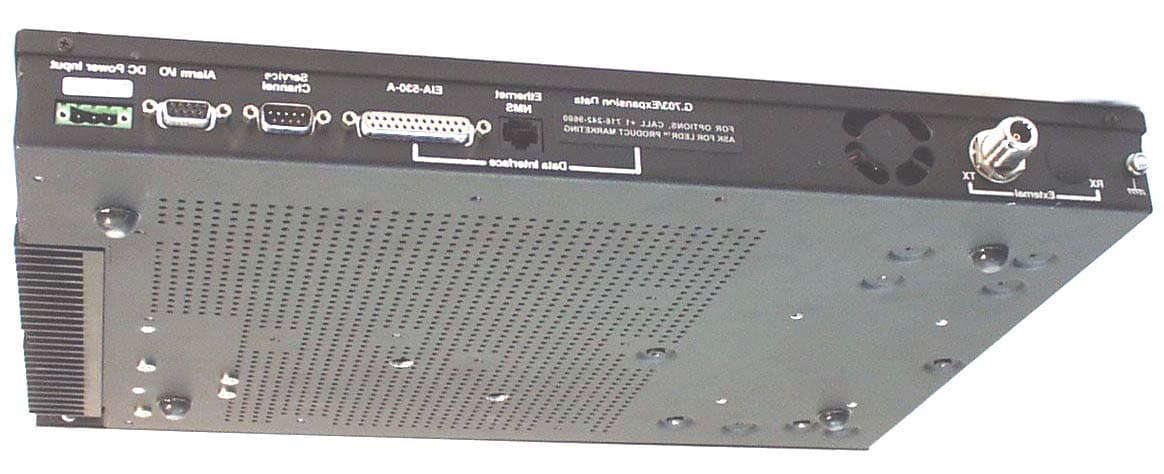
Click to zoom
Application Details
- Equipment Class
- TBC - Licensed Broadcast Station Transmitter
- Date of Grant
- Sep 26, 2001
- Application Purpose
- Original Equipment
- Date of Application
- Aug 01, 2001
- Equipment Note
- LEDR 400S Microwave Radio
- Frequency Range
- 450.05000000 - 455.85000000
- Company
- GE MDS, LLC
- Country
- United States
Documents & Files
Document Text
Text extracted from the exhibit documents filed with the FCC. Open a document above to read the original.
Users Manual
Installation and Operation Guide P/N 05-3627A01, Rev. C MARCH 2001 LEDR 400S/F, 900S/F, 1400S/F Series Including Protected (1+1) and Space Diversity Versions LEDR DIGITAL MICROWAVE RADIOS LEDR Series radios are supplied from the factory in matched pairs and will be configured to user’s specifications. There are a few steps necessary to place the pair on-the-air communi- cating with each other. Once this is done, system-specific parameters will need to be reviewed and changed to match your requirements. Below are the basic steps for installing the LEDR radio. For a more detailed installation procedure, please see “INITIAL STARTUP AND CONFIG- URATION” on page 24. When making cable connections, refer to Section 3.6, Rear Panel Con- nectors, on page 16 for a rear panel view of the radio. 1. Install and connect the antenna system to the radio • Ensure a path study has been conducted and that the radio path is acceptable. • Use good quality, low loss coaxial cable. Keep the feedline as short as possible. • Preset directional antennas in the direction of desired transmission/reception. 2. Connect the data equipment to the rear panel data interface • The data interface should be an RJ-45 connector for Fractional-T1, Fractional-E1, or E1, and DB-25 for EIA-530. • Verify the customer premises data equipment is configured as DTE. (By default, the LEDR radio is configured as DCE.) 3. Apply DC power to the radio • Verify that the line voltage matches the power supply input range (24 Vdc or 48 Vdc). • The power connector is a three-pin keyed connector. The power source can be connected with either polarity. The center conductor is not connected. 4. Change SUPER password and set up user access • Login to Network Management System as SUPER , using password SUPER . (See “login” on page 68 .) • Change the password using the PASSWD command. ( See “passwd” on page 73 ) • Set up required users, passwords and access levels using the USER command, as required. ( See “user” on page 86 ) 5. Set the radio’s basic configuration using front panel or Console interface • Set the transmit/receive frequencies ( TX xxx.xxxx / RX xxx.xxxx ) if they need to be changed from the factory settings. (See “freq” on page 58 .) • Refer to this manual for other configuration settings. 6. Verify and set as necessary the following parameters to allow data throughput and interconnection with the network. • RF transmit and receive frequencies. (See “freq” on page 58 .) • Radio modulation type and data rate parameters. ( See “modem” on page 72 ). • Data interface clocking. ( See “clkmode” on page 54 ). • Data framing. ( See “fstruct” on page 59 ). The Quick Start Guide is continued on the rear cover of this manual. QUICK START GUIDE MDS 05-3627A01, Rev. CLEDR Series Installation & Operation Guide i TABLE OF CONTENTS 1.0 INTRODUCTION ......................................................................... 1 1.1 Product Description .......................................................................... 1 1.2 LEDR Features ................................................................................ 2 1.3 Typical Applications .......................................................................... 2 1.4 Protected Configuration ................................................................... 3 2.0 MODEL NUMBER CODES.......................................................... 4 3.0 HARDWARE INSTALLATION & BASIC INTERFACE REQUIREMENTS ....................................................................... 7 3.1 Introduction ...................................................................................... 7 3.2 General Requirements ..................................................................... 7 Site Selection ................................................................................. 8 Terrain and Signal Strength............................................................ 8 On-the-Air Test ............................................................................... 9 A Word About Interference ............................................................. 9 3.3 Antenna and Feedline Selection .................................................... 10 Antennas ...................................................................................... 10 Feedlines ...................................................................................... 11 3.4 Radio Mounting .............................................................................. 12 Maximizing RSSI .......................................................................... 13 Attaching the Rack Mounting Brackets......................................... 13 3.5 Front Panel ..................................................................................... 13 Indicators, Text Display and Navigation Keys ............................... 13 Connectors ................................................................................... 16 3.6 Rear Panel Connectors .................................................................. 16 Connector Locations .................................................................... 17 Ground Stud ................................................................................. 17 Antenna/TX—RF Connector ........................................................ 18 RX—RF Connector ...................................................................... 18 G.703/Expansion Data ................................................................. 18 Ethernet........................................................................................ 19 EIA-530-A..................................................................................... 19 Service Channel ........................................................................... 19 Alarm I/O ...................................................................................... 20 DC Power Input (Primary Power) ................................................. 21 Protected Configu…
Text truncated - open the document above for the full version.
Users Manual
MDS 05-3627A01, Rev. CLEDR Series Installation & Operation Guide93 8.0 UPGRADING LEDR FIRMWARE 8.1 Introduction The LEDR radio’s firmware can be upgraded with new software releases that may be issued from time-to-time by Microwave Data Sys- tems. To support firmware upgrades while the radio is in use, the LEDR radio contains two complete copies of its firmware. Once the inactive version is replaced, the radio can be rebooted using the code in the new firmware. However, if an error occurs during the download, the radio can easily recover because it always has a complete copy of firmware available. Reprogramming can be done through three common options: 1. Locally through the front panel CONSOLE Port . 2. Locally using TFTP and Telnet through the ETHERNET Port . 3. Remotely over a network connection using TFTP and Telnet to the ETHERNET Port . The procedures that follow use one or both of two utilities found in MDS’ LEDR Utilities package. These utilities will facilitate local and remote transferring of firmware files to and from the LEDR radio. These applications are available from Microwave Data Systems on floppy disk (P/N 03-3631A01) or on MDS’ Internet sites FTP section of the primary site of www.microwavedata.com. The following sections will explain how to program new firmware into the radio using each of the three connection options. They assume the LEDR Utilities are installed on each computer system named in the pro- cedure. NOTE:The ETHERNET, SERVICE CHANNEL and CONSOLE Ports share a common data channel when loading firmware over-the-air. Transferring the radio firmware image file (≈ 1 MB), may take up to 30 minutes if there is other activity on any of the other ports. Regardless of your connection to the LEDR radio, loading data/firmware into the radio’s SRAM is much slower than loading software onto a PC hard drive or RAM. 94LEDR Series Installation & Operation GuideMDS 05-3627A01, Rev. C 8.2 OPTION 1: Uploading Firmware via the CONSOLE Port This method of upgrading the firmware is well suited to field service personnel that carry a laptop PC to field installation. Any computer run- ning the Windows operating system is suitable. Figure 17 shows the basic arrangement. Invisible place holder Figure 17. Direct connection through the LEDR CONSOLE Port Setup Connect a PC to the radio’s front panel CONSOLE Port using a 9-pin RS-232 cable. (See Figure 33 on Page 129 for cable wiring details.) The CONSOLE Port supports RS-232 at 9600 bps to 38.4 kbps. Download Procedure 1. Start the MDS MDS Flash Utility application. 2. From the View>Options menu, select the appropriate COM Port and baud rate. Ensure that autobaud is enabled (Look in the lower right-hand corner of the Flash Utility window). 3. From the View menu, select console. This will bring up a NMS win- dow to the LEDR radio. At the LEDR> prompt, enter a login name and password and then close the session. 4. Using the File|Open dialog, select the directory where the new firm- ware is located. In the file window, highlight the correct ( .mpk) file and then press the green start arrow. FLASH UTILITY COM1, 2, ETC. (DTE) 9-PIN SERIAL CABLE CONSOLE PORT (DCE) INITIATE UPLOAD FROM HERE LEDR RADIO UNITWINDOWS PC MDS 05-3627A01, Rev. CLEDR Series Installation & Operation Guide95 Verification and Reboot 1. To verify the correct operation of the new firmware, open the NMS again by pressing Alt + L. Enter boot to determine which image is currently active. This command will respond as follows: boot: Image 1 is Active or, boot: Image 2 is Active 2. The new firmware is downloaded into the inactive image. Therefore, if the radio responded Image 1 is Active, enter “image verify” com- mand, iverify 2, otherwise, enter iverify 1. The radio will respond indi- cating whether or not the image has been verified as being a valid file, it will not determine if the contents are complementary to the other firmware image. If the image does not verify, try downloading the firmware again into the radio. NOTE:The following paragraph describes rebooting the radio. This action will disrupt the communications link. 3. Once the image has been verified, the radio must be rebooted using the new firmware. This is done by entering the command boot 1 or boot 2, where the 1 or 2 corresponds with the image number used with the iverify command above. 4. Once the radio has rebooted and Flash Utility screen displays the LEDR> prompt, the firmware can be downloaded or copied into the other image. Often, copying the firmware from one image to the other can be faster than performing a second download. To copy the firmware over to the other image, simply enter icopy. The radio will prompt you for confirmation ( y/n) and then begin copying. 8.3 OPTION 2: Uploading Firmware Locally by Telnet via Ethernet This method can be used in the field or in a workshop by using a Win- dows computer equipped with an Ethernet interface. Figure 17 shows the basic arrangement. NOTE:You must know the IP address of the LEDR Radio and the PC that you are going to connect together. (Both units must have the same Subnet, Netmask and Gateway addresses, or at least have routes to one another.) This is essential for a direct Ethernet connection. If you do not know your Windows computer’s IP address, you can use the RUN function from the Start menu and enter winipcfg to determine your local PC’s IP address. The IP address of the radio can be found by the use of the radio’s ip command. 96LEDR Series Installation & Operation GuideMDS 05-3627A01, Rev. C Invisible place holder Figure 18. Direct connection through the LEDR ETHERNET Port Setup 1. Connect the PC’s Ethernet interface to the radio’s ETHERNET Port using a Category 5 Ethernet cross-over cable. 2. Copy the file LEDR firmware image file ( ledr.mpk) into a known directory on your PC. For example, c:\windows\LEDR\Firmware V2.5\. This directory path will be used later by the TFTP server. Download Procedure 1. Launch the MDS TFTP Server on a PC connected …
Text truncated - open the document above for the full version.
Cover Letter(s)
175 Science Parkway, Rochester, New York 14620 USA (716) 242-9600 Phone (716) 242-9620 Fax August 1, 2001 FEDERAL COMMUNICATIONS COMMISSION 7435 Oakland Mills Road Columbia, MD 21046 U.S.A. Subject: Authority to Act as an Agent to FCC Applicant: Microwave Data Systems Product: LEDR MICROWAVE RADIO Model: LEDR400S FCC ID: E5M-LEDR400S-74 Dear Sir/Madam, I hereby appoint UltraTech Engineering Labs Inc. (UltraTech) to act as my agent in preparation of this application to F.C.C. for authorization of equipment under F.C.C. Rules. I also certify that the information provided, properly described the device or system for which authorization is required. Regards Dennis McCarthy Dennis McCarthy Agency Compliance Engineer Microwave Data Systems 175 Science Parkway Rochester NY 14620 Phone (716) 242-8440 Email [email protected] 175 Science Parkway, Rochester, New York 14620 USA (716) 242-9600 Phone (716) 242-9620 Fax 6/28/01 To Industry Canada Subject: Authority to list the LEDR 400S for IC listing Applicant: Microwave Data Systems Inc. Product: LEDR Microwave Radio Model: LEDR400S FCC ID: E5M-LEDR400S-74 Dear Sir/Madam, I hereby appoint UltraTech Engineering Labs Inc. (UltraTech) to act as my agent in preparation of this application to I.C. for authorization of the above equipment under I.C. Rules. I also certify that the information provided, properly described the device or system for which authorization is required. Regards Dennis McCarthy Dennis McCarthy Agency Compliance Engineer Microwave Data Systems 175 Science Parkway Rochester NY 14620 Phone (716) 242-8440 Email [email protected]
Cover Letter(s)
175 Science Parkway, Rochester, New York 14620 USA (716) 242-9600 Phone (716) 242-9620 Fax August 1, 2001 FEDERAL COMMUNICATIONS COMMISSION 7435 Oakland Mills Road Columbia, MD 21046 U.S.A. Subject: Request for withholding from public disclosure the schematic diagrams and system block diagrams pursuant to an application for certification. Applicant: Microwave Data Systems Product: LEDR DIGITAL RADIOS Model: LEDR 400S FCC ID: E5M-LEDR400S-74 Dear Sir/Madam, We, Microwave Data Systems, would like to request that the schematic diagrams, system block diagrams, Theory of Operation and Bill of Materials submitted with the application for certification be withheld from public disclosure as per Section 0.459 of FCC Rules. This request is made under the provisions of Section 0.457(d) of the Commission's Rules, and Section 552(b)(4) of the Freedom of Information Act. These sections authorize as a withholding from public inspection materials which would be privileged as a matter of law if retained by the person submitting them, and materials which would not customarily be released to the public by that person. The detailed confidential materials are listed as follows: No. Title Drawing No. Sheet No. 1, Schematics 1 to 14 2, Theory of operation 3, Bills of materials 4, Block diagram If you have any queries, please do not hesitate to contact us at 716 242-9600: Yours truly, Dennis McCarthy Agency Compliance Engineer Microwave Data Systems 175 Science Parkway Rochester NY 14620 Phone (716) 242-8440 Email [email protected]
Cover Letter(s)
2 3000 Bristol Circle, Oakville, Ontario, Canada L6H 6G4 Telephone (905) 829-1570 Facsimile (905) 829-8050 Website: www.ultratech-labs.com Email: [email protected] UltraTech Group of Labs July 26, 2001 FEDERAL COMMUNICATIONS COMMISSION 7435 Oakland Mills Road Columbia, MD 21046 USA Subject: Certification Application under FCC 47 CFR, Part 74, Subpart D – Remote Pickup Broadcast Stations Operating in the Frequency Range of 450.05 to 455.85 MHz. Applicant: Microwave Data Systems Inc. Product: LEDR Microwave Radio Model: LEDR 400S FCC ID: E5M-LEDR400S-74 Dear Sir/Madam, As appointed agent for Microwave Data Systems Inc., we would like to submit this application to the Federal Communications Commission for certification of the above product. Tuning, system configuration and filter modules were changed to operate under 47 CFR, Part 74, Subpart D rules. Tuning was performed by, retuning the passive cavity tuned TX/RX duplexer, and by using the front panel and programming the TX/RX synthesizer frequencies. To increase the channel spacing from 25 kHz to 50 kHz, an upgrade kit consisting of 3 filter modules is installed in place of the existing modules. To activate the new changes, a software key, supplied by the factory and based on the product’s serial number is required. Refer to page 122 of the user’s manual for complete details including location and instructions on installing the filter modules. Refer to Section 3.5 of this report for information on the filters used. Please review all necessary files uploaded to the FCC OET site for complete information. If you have any queries, please do not hesitate to contact us by our TOLL FREE number: OUR TELEPHONE NO.: 1-877-765-4173 Yours truly, Tri Minh Luu, P. Eng., V.P., Engineering TML/MT Encl.
Cover Letter(s)
2 3000 Bristol Circle Oakville, Ontario Canada, L6H 6G4 Telephone (905) 569-2550 Facsimile (905) 569-2480 Web Site: www.ultratech-labs.com Email: [email protected] September 20, 2001 Federal Communications Commission FCC Application Processing Branch 7435 Oakland Mills Road Columbia, MD 21046 USA Attn.: Mr. Stan Lyles Re: FCC ID: E5M-LEDR400S-74 Applicant: MICROWAVE DATA SYSTEMS, INC. Correspondence Reference Number: 20682 731 Confirmation Number: EA101892 Dear Mr. Lyes, This letter is our reply to the Above Referenced Number. Our reply for each of the numbered items shown in the email message are as follows: (1) New plots, with an increased sweep time have been uploaded. Refer to the exhibits labeled “Tx Conducted Data plots” (2) Page 18, Section 6.9.5 of the test report, makes reference to “...refer to Plots #21 to 40...”. This is a cut and paste editing error. This statement should have been deleted. Test data shows that all significant emissions found were more than 20 dB below the most stringent limit and therefore need not be reported. (3) 50K0D1W emissions was provided by the applicant representing the maximum emission bandwidth. Please change all references of 50K0D1W to 41K3D1W. If you have any queries, please do not hesitate to contact us. Yours truly, Tri M. Luu, P. Eng. V.P., Engineering Encl. TML/MT UltraTech Group of Labs
External Photos
MICROWAVE DATA SYSTEMS LEDR MICROWAVE RADIO LEDR 400S ANNEX C - EXTERNAL VIEWS OF EUT PHOTO # 1 OF 3 FCC ID: E5M-LEDR400S-74 MICROWAVE DATA SYSTEMS LEDR MICROWAVE RADIO LEDR 400S ANNEX C - EXTERNAL VIEWS OF EUT PHOTO # 2 OF 3 FCC ID: E5M-LEDR400S-74 MICROWAVE DATA SYSTEMS LEDR MICROWAVE RADIO LEDR 400S ANNEX C - EXTERNAL VIEWS OF EUT PHOTO # 3 OF 3 FCC ID: E5M-LEDR400S-74
Internal Photos
MICROWAVE DATA SYSTEMS LEDR MICROWAVE RADIO LEDR 400S ANNEX D - INTERNAL EUT PHOTOS PHOTO # 1 of 8 FCC ID: E5M-LEDR400S-74 MICROWAVE DATA SYSTEMS LEDR MICROWAVE RADIO LEDR 400S ANNEX D - INTERNAL EUT PHOTOS PHOTO # 2 of 8 FCC ID: E5M-LEDR400S-74 MICROWAVE DATA SYSTEMS LEDR MICROWAVE RADIO LEDR 400S ANNEX D - INTERNAL EUT PHOTOS PHOTO # 3 of 8 FCC ID: E5M-LEDR400S-74 MICROWAVE DATA SYSTEMS LEDR MICROWAVE RADIO LEDR 400S ANNEX D - INTERNAL EUT PHOTOS PHOTO # 4 of 8 FCC ID: E5M-LEDR400S-74 MICROWAVE DATA SYSTEMS LEDR MICROWAVE RADIO LEDR 400S ANNEX D - INTERNAL EUT PHOTOS PHOTO # 5 of 8 FCC ID: E5M-LEDR400S-74 MICROWAVE DATA SYSTEMS LEDR MICROWAVE RADIO LEDR 400S ANNEX D - INTERNAL EUT PHOTOS PHOTO # 6 of 8 FCC ID: E5M-LEDR400S-74 MICROWAVE DATA SYSTEMS LEDR MICROWAVE RADIO LEDR 400S ANNEX D - INTERNAL EUT PHOTOS PHOTO # 7 of 8 FCC ID: E5M-LEDR400S-74 MICROWAVE DATA SYSTEMS LEDR MICROWAVE RADIO LEDR 400S ANNEX D - INTERNAL EUT PHOTOS PHOTO # 8 of 8 FCC ID: E5M-LEDR400S-74
Test Report
MICROWAVE DATA SYSTEMS INC. LEDR MICROWAVE RADIO MODEL: LEDR 400S ANNEX A – TEST DATA MEASUREMENT PLOTS FCC ID: E5M-LEDR400S-74 PLOT #1 OF 40 MICROWAVE DATA SYSTEMS INC. LEDR MICROWAVE RADIO MODEL: LEDR 400S ANNEX A – TEST DATA MEASUREMENT PLOTS FCC ID: E5M-LEDR400S-74 PLOT #2 OF 40 MICROWAVE DATA SYSTEMS INC. LEDR MICROWAVE RADIO MODEL: LEDR 400S ANNEX A – TEST DATA MEASUREMENT PLOTS FCC ID: E5M-LEDR400S-74 PLOT #3 OF 40 MICROWAVE DATA SYSTEMS INC. LEDR MICROWAVE RADIO MODEL: LEDR 400S ANNEX A – TEST DATA MEASUREMENT PLOTS FCC ID: E5M-LEDR400S-74 PLOT #4 OF 40 MICROWAVE DATA SYSTEMS INC. LEDR MICROWAVE RADIO MODEL: LEDR 400S ANNEX A – TEST DATA MEASUREMENT PLOTS FCC ID: E5M-LEDR400S-74 PLOT #5 OF 40 MICROWAVE DATA SYSTEMS INC. LEDR MICROWAVE RADIO MODEL: LEDR 400S ANNEX A – TEST DATA MEASUREMENT PLOTS FCC ID: E5M-LEDR400S-74 PLOT #6 OF 40 MICROWAVE DATA SYSTEMS INC. LEDR MICROWAVE RADIO MODEL: LEDR 400S ANNEX A – TEST DATA MEASUREMENT PLOTS FCC ID: E5M-LEDR400S-74 PLOT #7 OF 40 MICROWAVE DATA SYSTEMS INC. LEDR MICROWAVE RADIO MODEL: LEDR 400S ANNEX A – TEST DATA MEASUREMENT PLOTS FCC ID: E5M-LEDR400S-74 PLOT #8 OF 40 MICROWAVE DATA SYSTEMS INC. LEDR MICROWAVE RADIO MODEL: LEDR 400S ANNEX A – TEST DATA MEASUREMENT PLOTS FCC ID: E5M-LEDR400S-74 PLOT #9 OF 40 MICROWAVE DATA SYSTEMS INC. LEDR MICROWAVE RADIO MODEL: LEDR 400S ANNEX A – TEST DATA MEASUREMENT PLOTS FCC ID: E5M-LEDR400S-74 PLOT #10 OF 40
Test Report
MICROWAVE DATA SYSTEMS INC. LEDR MICROWAVE RADIO MODEL: LEDR 400S ANNEX A – TEST DATA MEASUREMENT PLOTS FCC ID: E5M-LEDR400S-74 PLOT #11 OF 40 MICROWAVE DATA SYSTEMS INC. LEDR MICROWAVE RADIO MODEL: LEDR 400S ANNEX A – TEST DATA MEASUREMENT PLOTS FCC ID: E5M-LEDR400S-74 PLOT #12 OF 40 MICROWAVE DATA SYSTEMS INC. LEDR MICROWAVE RADIO MODEL: LEDR 400S ANNEX A – TEST DATA MEASUREMENT PLOTS FCC ID: E5M-LEDR400S-74 PLOT #13 OF 40 MICROWAVE DATA SYSTEMS INC. LEDR MICROWAVE RADIO MODEL: LEDR 400S ANNEX A – TEST DATA MEASUREMENT PLOTS FCC ID: E5M-LEDR400S-74 PLOT #14 OF 40 MICROWAVE DATA SYSTEMS INC. LEDR MICROWAVE RADIO MODEL: LEDR 400S ANNEX A – TEST DATA MEASUREMENT PLOTS FCC ID: E5M-LEDR400S-74 PLOT #15 OF 40 MICROWAVE DATA SYSTEMS INC. LEDR MICROWAVE RADIO MODEL: LEDR 400S ANNEX A – TEST DATA MEASUREMENT PLOTS FCC ID: E5M-LEDR400S-74 PLOT #16 OF 40 MICROWAVE DATA SYSTEMS INC. LEDR MICROWAVE RADIO MODEL: LEDR 400S ANNEX A – TEST DATA MEASUREMENT PLOTS FCC ID: E5M-LEDR400S-74 PLOT #17 OF 40 MICROWAVE DATA SYSTEMS INC. LEDR MICROWAVE RADIO MODEL: LEDR 400S ANNEX A – TEST DATA MEASUREMENT PLOTS FCC ID: E5M-LEDR400S-74 PLOT #18 OF 40 MICROWAVE DATA SYSTEMS INC. LEDR MICROWAVE RADIO MODEL: LEDR 400S ANNEX A – TEST DATA MEASUREMENT PLOTS FCC ID: E5M-LEDR400S-74 PLOT #19 OF 40 MICROWAVE DATA SYSTEMS INC. LEDR MICROWAVE RADIO MODEL: LEDR 400S ANNEX A – TEST DATA MEASUREMENT PLOTS FCC ID: E5M-LEDR400S-74 PLOT #20 OF 40
Test Report
MICROWAVE DATA SYSTEMS INC. LEDR MICROWAVE RADIO MODEL: LEDR 400S ANNEX A – TEST DATA MEASUREMENT PLOTS FCC ID: E5M-LEDR400S-74 PLOT #21 OF 40 MICROWAVE DATA SYSTEMS INC. LEDR MICROWAVE RADIO MODEL: LEDR 400S ANNEX A – TEST DATA MEASUREMENT PLOTS FCC ID: E5M-LEDR400S-74 PLOT #22 OF 40 MICROWAVE DATA SYSTEMS INC. LEDR MICROWAVE RADIO MODEL: LEDR 400S ANNEX A – TEST DATA MEASUREMENT PLOTS FCC ID: E5M-LEDR400S-74 PLOT #23 OF 40 MICROWAVE DATA SYSTEMS INC. LEDR MICROWAVE RADIO MODEL: LEDR 400S ANNEX A – TEST DATA MEASUREMENT PLOTS FCC ID: E5M-LEDR400S-74 PLOT #24 OF 40 MICROWAVE DATA SYSTEMS INC. LEDR MICROWAVE RADIO MODEL: LEDR 400S ANNEX A – TEST DATA MEASUREMENT PLOTS FCC ID: E5M-LEDR400S-74 PLOT #25 OF 40 MICROWAVE DATA SYSTEMS INC. LEDR MICROWAVE RADIO MODEL: LEDR 400S ANNEX A – TEST DATA MEASUREMENT PLOTS FCC ID: E5M-LEDR400S-74 PLOT #26 OF 40 MICROWAVE DATA SYSTEMS INC. LEDR MICROWAVE RADIO MODEL: LEDR 400S ANNEX A – TEST DATA MEASUREMENT PLOTS FCC ID: E5M-LEDR400S-74 PLOT #27 OF 40 MICROWAVE DATA SYSTEMS INC. LEDR MICROWAVE RADIO MODEL: LEDR 400S ANNEX A – TEST DATA MEASUREMENT PLOTS FCC ID: E5M-LEDR400S-74 PLOT #28 OF 40 MICROWAVE DATA SYSTEMS INC. LEDR MICROWAVE RADIO MODEL: LEDR 400S ANNEX A – TEST DATA MEASUREMENT PLOTS FCC ID: E5M-LEDR400S-74 PLOT #29 OF 40 MICROWAVE DATA SYSTEMS INC. LEDR MICROWAVE RADIO MODEL: LEDR 400S ANNEX A – TEST DATA MEASUREMENT PLOTS FCC ID: E5M-LEDR400S-74 PLOT #30 OF 40 MICROWAVE DATA SYSTEMS INC. LEDR MICROWAVE RADIO MODEL: LEDR 400S ANNEX A – TEST DATA MEASUREMENT PLOTS FCC ID: E5M-LEDR400S-74 PLOT #31 OF 40 MICROWAVE DATA SYSTEMS INC. LEDR MICROWAVE RADIO MODEL: LEDR 400S ANNEX A – TEST DATA MEASUREMENT PLOTS FCC ID: E5M-LEDR400S-74 PLOT #32 OF 40 MICROWAVE DATA SYSTEMS INC. LEDR MICROWAVE RADIO MODEL: LEDR 400S ANNEX A – TEST DATA MEASUREMENT PLOTS FCC ID: E5M-LEDR400S-74 PLOT #33 OF 40 MICROWAVE DATA SYSTEMS INC. LEDR MICROWAVE RADIO MODEL: LEDR 400S ANNEX A – TEST DATA MEASUREMENT PLOTS FCC ID: E5M-LEDR400S-74 PLOT #34 OF 40 MICROWAVE DATA SYSTEMS INC. LEDR MICROWAVE RADIO MODEL: LEDR 400S ANNEX A – TEST DATA MEASUREMENT PLOTS FCC ID: E5M-LEDR400S-74 PLOT #35 OF 40 MICROWAVE DATA SYSTEMS INC. LEDR MICROWAVE RADIO MODEL: LEDR 400S ANNEX A – TEST DATA MEASUREMENT PLOTS FCC ID: E5M-LEDR400S-74 PLOT #36 OF 40 MICROWAVE DATA SYSTEMS INC. LEDR MICROWAVE RADIO MODEL: LEDR 400S ANNEX A – TEST DATA MEASUREMENT PLOTS FCC ID: E5M-LEDR400S-74 PLOT #37 OF 40 MICROWAVE DATA SYSTEMS INC. LEDR MICROWAVE RADIO MODEL: LEDR 400S ANNEX A – TEST DATA MEASUREMENT PLOTS FCC ID: E5M-LEDR400S-74 PLOT #38 OF 40 MICROWAVE DATA SYSTEMS INC. LEDR MICROWAVE RADIO MODEL: LEDR 400S ANNEX A – TEST DATA MEASUREMENT PLOTS FCC ID: E5M-LEDR400S-74 PLOT #39 OF 40 MICROWAVE DATA SYSTEMS INC. LEDR MICROWAVE RADIO MODEL: LEDR 400S ANNEX A – TEST DATA MEASUREMENT PLOTS FCC ID: E5M-LEDR400S-74 PLOT #40 OF 40
Test Report
FOR LEDR Microwave Radio Model: LEDR 400S FCC ID: E5M-LEDR400S-74 IN ACCORDANCE WITH FEDERAL COMMUNICATIONS COMMISSION (FCC) REMOTE BROADCAST PICKUP STATIONS 47 CFR, PARTS 2 and 74, Subpart D TESTED FOR Applicant: Microwave Data Systems Inc. 175 Science Parkway Rochester, NY USA, 14620-4261 ULTRATECH FILE NO. MIC44_F74 This Test Report is hereby issued under the Authority of Tri M. Luu, Professional Engineer, Vice President of Engineering UltraTech Group of Labs Inc. Date: ___________________________ Report Prepared By: Mike Tom Tested By: Hung Trinh, RFI Technician __________________________________ ___________________________________ Date: July 26, 2001 Date: June 4-5, 2001 1. The Results contained in this Test Report apply only to the sample tested, which is randomly selected. 2. This report may not be reproduced in whole or in part without the prior written consent of UltraTech Engineering Labs Inc. 3. Under no circumstances may this report be used by the client to claim product endorsement by NVLAP or any agency of the US Government. ULTRATECH 3000 BRISTOL CIRCLE, OAKVILLE, ONTARIO, CANADA, L6H 6G4 Telephone: 905-829-1570, Fax: 905-829-8050 Website: www.ultratech-labs.com Email: [email protected] , [email protected] FCC CFR 47, Parts 2 and 74, Subpart D – Remote Pickup Broadcast Stations LEDR Microwave Radio, Model LEDR 400S FCC ID: E5M-LEDR400S-74 ULTRATECH GROUP OF LABS File #: MIC44_F74 3000 Bristol Circle, Oakville, Ontario, Canada L6H 6G4 July 26, 2001 Tel. #: 905-829-1570, Fax. #: 905-829-8050, Email: [email protected], Website: http://www.ultratech-labs.com • Assessed by ITI (UK) Competent Body, NVLAP (USA) Accreditation Body & ACA/AUSTEL (Australia) • Accredited by Industry Canada (Canada) under ACC-LAB (Europe/Canada MRA) • Recognized/Listed by FCC (USA ) All test results contained in this engineering test report are traceable to National Institute of Standards and Technology (NIST) TABLE OF CONTENTS EXHIBIT 1. SUBMITTAL CHECK LIST................................................................................................................3 EXHIBIT 2. INTRODUCTION ...............................................................................................................................4 2.1. SCOPE .....................................................................................................................................................4 2.2. NORMATIVE REFERENCES...................................................................................................................4 EXHIBIT 3. PERFORMANCE ASSESSMENT .....................................................................................................5 3.1. APPLICANT INFORMATION ...................................................................................................................5 3.2. EQUIPMENT UNDER TEST (EUT) INFORMATION ...............................................................................5 3.3. EUT’S TECHNICAL SPECIFICATIONS...................................................................................................6 3.4. LIST OF EUT’S PORTS ...........................................................................................................................7 3.5. MODIFICATIONS INCORPORATED IN THE EUT FOR COMPLIANCE PURPOSES ...........................7 EXHIBIT 4. EUT OPERATING CONDITIONS AND CONFIGURATIONS DURING TESTS ...............................8 4.1. CLIMATE TEST CONDITIONS ................................................................................................................8 4.2. OPERATIONAL TEST CONDITIONS & ARRANGEMENT FOR TEST SIGNALS ..................................8 EXHIBIT 5. SUMMARY OF TEST RESULTS ......................................................................................................9 5.1. LOCATION OF TESTS.............................................................................................................................9 5.2. APPLICABILITY & SUMMARY OF EMC EMISSION TEST RESULTS...................................................9 EXHIBIT 6. MEASUREMENTS, EXAMINATIONS & TEST DATA FOR EMC EMISSIONS .............................10 6.1. TEST PROCEDURES ............................................................................................................................10 6.2. MEASUREMENT UNCERTAINTIES......................................................................................................10 6.3. MEASUREMENT EQUIPMENT USED ..................................................................................................10 6.4. ESSEN…
Text truncated - open the document above for the full version.
Contact Information
Applicant
John Barenys(Senior Operations Manager)
Technical Contact
Ultratech Engineering Labs Inc.Tri M Luu
[email protected]1-877-765-4173
3000 Bristol Circle · Oakville, Ontario · Canada
Non-Technical Contact
Ultratech Engineering Labs Inc.Tri M Luu
[email protected]1-877-765-4173
Test Firm
UltraTech Engineering Labs Inc.Tri Luu
Technical Specifications
| # | Rule Parts | Frequency Range | Power Output | Emission | Tolerance |
|---|---|---|---|---|---|
| 2 | 74 | 450.05 MHz - 455.85 MHz | 1 W | 41K3D1W | 1 ppm |
Other Applications from GE MDS, LLC

E5MDS-NET9S
Jul 13, 2023Frequency Hopping Radio
Equipment Class
DSS - Part 15 Spread Spectrum Transmitter
E5MDS-NET9L
Jul 11, 2023Frequency Hopping Radio
Equipment Class
DSS - Part 15 Spread Spectrum Transmitter
E5MDS-LN900
Jan 27, 2016Industrial Radio Module
Equipment Class
TNB - Licensed Non-Broadcast Station Transmitter
E5MDS-SDM4
Aug 20, 2015MDS SDM4 Licensed Spectrum Module
Equipment Class
TNB - Licensed Non-Broadcast Station Transmitter
E5MDS-LN400
Jul 09, 2015Industrial Radio Module
Equipment Class
TNB - Licensed Non-Broadcast Station Transmitter