E5MDS-1710MDS1710 Data Transceiver
GE MDS, LLC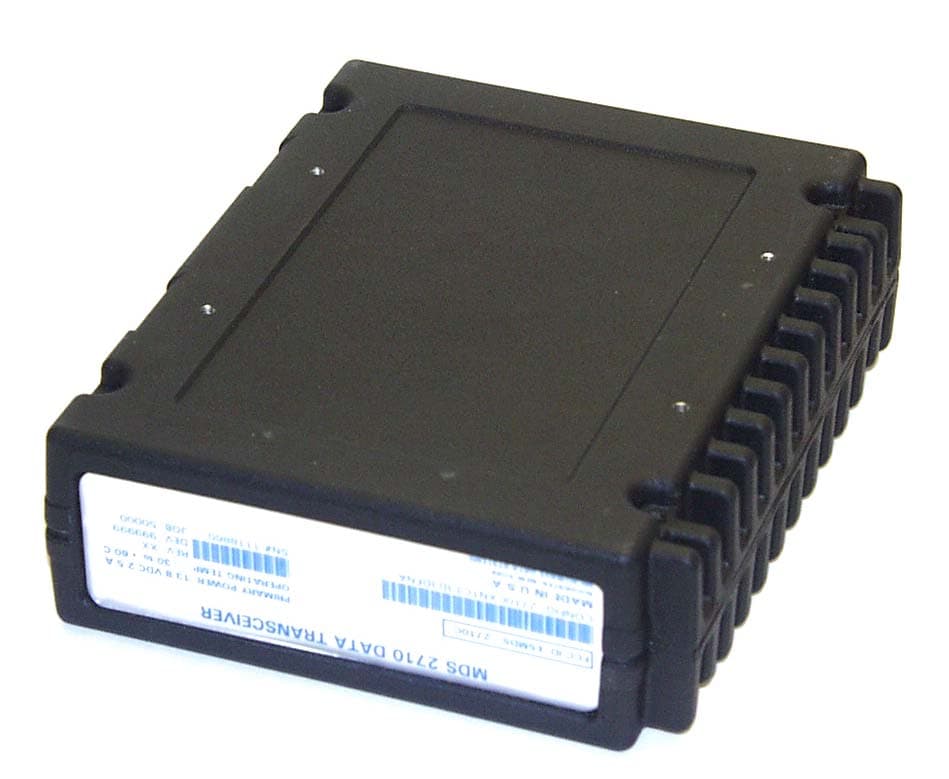
Click to zoom
Application Details
- Equipment Class
- TNB - Licensed Non-Broadcast Station Transmitter
- Date of Grant
- Feb 22, 2003
- Application Purpose
- Original Equipment
- Date of Application
- Feb 22, 2003
- Equipment Note
- MDS1710 Data Transceiver
- Frequency Range
- 150.00000000 - 174.00000000
- Company
- GE MDS, LLC
- Country
- United States
Documents & Files
Document Text
Text extracted from the exhibit documents filed with the FCC. Open a document above to read the original.
Users Manual
Installation & Operation Guide MDS 05-3447A01, REV. E FEBRUARY 2003 Data Transceiver Microwave Data Systems Inc. MDS 1710 A/C/F MDS 2710A/C/D QUICK START GUIDE Below are the basic steps for installing the transceiver. Detailed instructions are provided in “Installation Steps” on Page 9 of this manual. 1. Install and connect the antenna system to the radio • Use good quality, low loss coaxial cable. Keep the feedline as short as possible. • Preset directional antennas in the direction of desired transmission. 2. Connect the data equipment to the radio’s INTERFACE connector • Connection to the radio must be made with a DB-25 Male connector. Connections for typical sys- tems are shown below. • Connect only the required pins. Do not use a straight-through RS-232 cable with all pins wired. • Verify the data equipment is configured as DTE. (By default, the radio is configured as DCE.) 3. Apply DC power to the radio (10.5–16 Vdc @ 2.5 A minimum) • Observe proper polarity. The red wire is the positive lead; the black is negative. 4. Set the radio’s basic configuration with a Hand-Held Terminal (HHT) • Set the transmit frequency ( TX xxx.xxxxx ). • Set the receive frequency ( RX xxx.xxxxx ). • Set/verify the data rate using the BAUD command. The default setting is BAUD 4800 8N1 . (Refer to “TRANSCEIVER PROGRAMMING” on Page 17 for command details.) 5. Verify proper operation by observing the LED display • Refer to Table 5 on page 16 for a description of the status LEDs. • Refine directional antenna headings for maximum receive signal strength using the RSSI com- mand. DB-25DB-25 TRANSCEIVER (DCE) 2 3 2 3 RTU (DTE) 4 5 20 6DSR DSR 6 TXD RXD GND RTS CTS TXD RXD GND 4 CTS 5 RTS DB-9DB-25 DB-9 to DB-25 ExampleDB-25 to DB-25 Example 11 4 5 TRANSCEIVER (DCE) 2 3 3 2 RTU (DTE) 5 20 7 RXD TXD DCD GND DSR RTS RXD TXD DCD GND As required for application 5 18 7 6 CTS DSR RTS CTS8 6 4 5 77 GND GND 88 DCD DCD As required for application MDS 05-3447A01, Rev. EMDS 1710A/C/F and MDS 2710A/C/Di TABLE OF CONTENTS 1.0 GENERAL.................................................................................... 1 1.1 Introduction ...................................................................................... 1 1.2 Differences Between Models ........................................................... 2 1.3 Applications ...................................................................................... 2 Point-to-Multipoint, Multiple Address Systems (MAS) .................... 2 Point-to-Point System ..................................................................... 3 Continuously Keyed versus Switched Carrier Operation ................ 4 Single Frequency (Simplex) Operation ........................................... 4 1.4 Product Configurator Codes ............................................................. 4 1.5 Accessories ...................................................................................... 5 2.0 GLOSSARY OF TERMS.............................................................. 5 3.0 INSTALLATION ............................................................................ 8 3.1 Installation Steps .............................................................................. 9 3.2 Transceiver Mounting ..................................................................... 11 3.3 Antennas and Feedlines ................................................................ 11 Feedlines ...................................................................................... 12 3.4 Power Connection .......................................................................... 12 3.5 Data Interface Connections ............................................................ 13 3.6 Using the Radio’s Sleep Mode ....................................................... 13 Sleep Mode Example ................................................................... 13 4.0 OPERATION .............................................................................. 15 4.1 LED Indicators ................................................................................ 16 4.2 RSSI Measurement ........................................................................ 16 5.0 TRANSCEIVER PROGRAMMING ............................................ 17 5.1 Hand-Held Terminal Connection & Startup .................................... 17 5.2 Hand-Held Terminal Setup ............................................................. 18 5.3 Keyboard Commands ..................................................................... 19 Entering Commands ..................................................................... 19 Error Messages ............................................................................ 19 5.4 Detailed Command Descriptions ................................................... 22 AMASK [0000 0000–FFFF FFFF] ................................................ 22 ASENSE [HI/LO]........................................................................... 23 BAUD [xxxxx abc] ......................................................................... 23 BUFF [ON, OFF]........................................................................... 23 CKEY [ON–OFF] .......................................................................... 24 CTS [0–255] ................................................................................. 24 DATAKEY [ON, OFF] .................................................................... 24 DEVICE [DCE, CTS KEY] ............................................................ 24 DKEY ............................................................................................ 25 iiMDS 1710A/C/F and MDS 2710A/C/DMDS 05-3447A01, Rev. E DLINK [ON/OFF/xxxx] .................................................................. 25 DMGAP [xx] .................................................................................. 25 DTYPE [NODE/ROOT] ................................................................. 25 DUMP ................…
Text truncated - open the document above for the full version.
Attestation Statements
175 Science Parkway, Rochester, New York 14620 USA (585) 242-9600 Phone (585) 242-9620 Fax January 10, 2003 To whom it may concern Subject: Test procedure for the MDS1710 Mask Measurements Test Equipment used: Test Instrument, Spectrum Analyzer Manufacturer, Hewlett Packard Model, HP8563E S/N, 3517A03418 Range of Operation 9 KHz - 26.5 GHz Calibration Date 13NOV2002 due:13NOV2004 1, 20dB, 10 watt attenuator, manufacturer JFW model 50FH-020-10 1, 2ft piece of RG214 double shielded coax cable I certify the MDS1710 is a 5 watt (+37dBm) transceiver and the transmit mask plots simply did not have the reference input changed to show the +37dBm power level. The transmitter output level of +36.83dBm minus the 20dB attenuation equals the +16.83dB referenced on all the 12.5KHz plots. These transmit masks were measured and plotted at MDS and the 25KHz mask plots were measured at Ultratech at a much earlier date. In the interest of completing the program the 12.5KHz plots were measured at MDS and submitted to Ultratech January 6th. Respectfully Dennis McCarthy Dennis McCarthy Agency Compliance Engineer Microwave Data Systems 175 Science Parkway Rochester NY 14620 Phone (585) 242-8440 Email [email protected] HP8563E Spectrum Analyzer Max +30dBm Input 20dB att. MDS1710 EUT +37dBm output The MDS1710A is a 5 Watt, 37dBm radio. The power level of 16.83 dBm is indicated on our submission plots. The radio is transmitting +36.83dBm – 20dB atten.= +16.83dBm Laptop or HHT to control the EUT
Cover Letter(s)
175 Science Parkway, Rochester, New York 14620 USA (585) 242-9600 Phone (585) 242-9620 Fax November 13, 2002 FEDERAL COMMUNICATIONS COMMISSION 7435 Oakland Mills Road Columbia, MD 21046 U.S.A. Subject: Request for withholding from public disclosure the schematic diagrams and system block diagrams pursuant to an application for certification. Applicant: Microwave Data Systems Inc. Product: MDS1710 Data Transceiver Model: MDS1710A/C FCC ID: E5MDS-1710 Dear Sir/Madam, We, Microwave Data Systems Inc., would like to request that the schematic diagrams, system block diagram, Theory of Operation and Bill of Materials submitted with the application for certification be withheld from public disclosure as per Section 0.459 of FCC Rules. This request is made under the provisions of Section 0.457(d) of the Commission's Rules, and Section 552(b)(4) of the Freedom of Information Act. These sections authorize as a withholding from public inspection materials which would be privileged as a matter of law if retained by the person submitting them, and materials which would not customarily be released to the public by that person. If you have any queries, please do not hesitate to contact me at 585 242-8440: Yours truly, Dennis McCarthy Agency Compliance Engineer Microwave Data Systems 175 Science Parkway Rochester NY 14620 Phone (585) 242-8440 Email [email protected]
Cover Letter(s)
175 Science Parkway, Rochester, New York 14620 USA (585) 242-9600 Phone (585) 242-9620 Fax November 13, 2002 FEDERAL COMMUNICATIONS COMMISSION 7435 Oakland Mills Road Columbia, MD 21046 U.S.A. Subject: Authority to Act as an Agent to FCC Applicant: Microwave Data Systems Inc. Product: MDS1710 Data Transceiver Model: MDS1710A/C FCC ID: E5MDS-1710 Dear Sir/Madam, I hereby appoint UltraTech Engineering Labs Inc. (UltraTech) to act as my agent in preparation of this application to F.C.C. for authorization of equipment under F.C.C. Rules. I also certify that the information provided, properly described the device or system for which authorization is required. If you have any queries, please do not hesitate to contact me at 585 242-8440: Yours truly, Dennis McCarthy Agency Compliance Engineer Microwave Data Systems 175 Science Parkway Rochester NY 14620 Phone (585) 242-8440 Email [email protected]
Cover Letter(s)
February 12, 2003 AmericanTCB, Inc. 6731 Whittier Avenue, Suite C110 McLean, VA 22101 Subject: Type Acceptance Application under FCC 47 CFR, Parts 2 and 90 (Subpart I) - Non-Broadcast Radio Transceivers Operating in the Frequency Band(s) 150 - 174 MHz (12.5 kHz and 25 kHz Channel Spacings). Applicant: Microwave Data Systems Inc. Product: MDS1710 Data Transceiver Model: MDS1710A and MDS1710C FCC ID: E5MDS-1710 Dear Sir/Madam, As appointed agent for Microwave Data Systems Inc., we would like to submit the application to Federal Communications Commission for certification of the above product. Please review all necessary files uploaded to ATCB electronic filing site. If you have any queries, please do not hesitate to contact us by our TOLL FREE number: OUR TELEPHONE NO.: 1-877-747-6381 Yours truly, Tri Minh Luu, P. Eng., V.P., Engineering TML/DH Encl. UltraTech Group of Labs 31040/SIT C-1376 46390-2049 200093-0 2 00-034 3000 Bristol Circle, Oakville, Ontario, Canada L6H 6G4 Tel.: (905) 829-1570 Fax.: (905) 829-8050 Website: www.ultratech-labs.com Email: [email protected]
Cover Letter(s)
American Telecommunications Certification Body Inc. 6731 Whittier Ave, McLean, VA 22101 February 19, 2003 RE: FCC ID: E5MDS-1710 Attention: Tri M. Luu I have a few comments on this Application. 1. Please provide the factory ‘tune up’ procedures used to set maximum peak deviation. 2. The values in the emissions designator and the measured values in the data do not seem to correlate very well. Please explain. 3. The low power listed on the grant and the low power listed in the report are not the same. Please correct the 731 to show the maximum measured low power setting values. (20.84dBm or 121mW). Alternately please explain why the measured power is not what is listed on the 731 (the FCC requires TCBs to list the measured readings on grants). Dennis Ward mailto:[email protected] The items indicated above must be submitted before processing can continue on the above referenced application. Failure to provide the requested information may result in application termination. Correspondence should be considered part of the permanent submission and may be viewed from the Internet after a Grant of Equipment Authorization is issued. Please do not respond to this correspondence using the email reply button. In order for your response to be processed expeditiously, you must submit your documents through the AmericanTCB.com website. Also, please note that partial responses increase processing time and should not be submitted. Any questions about the content of this correspondence should be directed to the sender.
Cover Letter(s)
1 dward From: [email protected] Sent: Thursday, February 20, 2003 2:31 AM To: [email protected] Cc: [email protected] Subject: MESSAGE attached to E5MDS-1710_ATCB000237 by uelrfiatcb From: Mr. Tri Luu (uelrfiatcb) Microwave Data Systems Inc. answer to question #1 about alignment is formal below: The X710 Family of transceivers that are designed and manufactured by MDS have NO user adjustable parts for transmitter alignment. Only the receiver front end filters are adjustable. The Transmit deviation is hard coded in DSP software and locked to a peak deviation depending on the model that is programmed in at the time of manufacture. The DSP modulates the both the VCO and TCXO and uses 2 point modulation and this is calibrated in a auto test by computer when the radio is calibrated in the factory. There all kind of checksums and peak deviation limits that will never allow the DSP to over modulate the transmitter. If there is a hard failure in the field of the transmitter, the unit must be returned to the factory for repair and re-calibration. Thus this ensures the FCC mask limits for repairs. Our auto test is quite complex and under our ISO-2000 monitoring process. Answer to question #2: The necessary bandwidth on the emissions designator is obtained from calculation as per FCC’s rule, unless there is no prescribed method. This calculated necessary bandwidth is not 26dB or 99% bandwidth. Therefore, it is not necessary to have direct correlation to the measured values. Answer to question #3: See revised Form 731 uploaded to ATCB electronic filing site.
External Photos
ANNEX 3 – EXTERNAL EUT PHOTOS Microwave Data Systems Inc. MDS1710 Data Transceiver, Model MDS1710A and MDS1710C FCC ID: E5MDS-1710 IC: 3738A-MDS1710 A3 - 1 ANNEX 3 – EXTERNAL EUT PHOTOS Microwave Data Systems Inc. MDS1710 Data Transceiver, Model MDS1710A and MDS1710C FCC ID: E5MDS-1710 IC: 3738A-MDS1710 A3 - 2
Internal Photos
ANNEX 4 – INTERNAL EUT PHOTOS Microwave Data Systems Inc. MDS1710 Data Transceiver, Model MDS1710A and MDS1710C FCC ID: E5MDS-1710 IC: 3738A-MDS1710 A4 - 1 ANNEX 4 – INTERNAL EUT PHOTOS Microwave Data Systems Inc. MDS1710 Data Transceiver, Model MDS1710A and MDS1710C FCC ID: E5MDS-1710 IC: 3738A-MDS1710 A4 - 2 ANNEX 4 – INTERNAL EUT PHOTOS Microwave Data Systems Inc. MDS1710 Data Transceiver, Model MDS1710A and MDS1710C FCC ID: E5MDS-1710 IC: 3738A-MDS1710 A4 - 3 ANNEX 4 – INTERNAL EUT PHOTOS Microwave Data Systems Inc. MDS1710 Data Transceiver, Model MDS1710A and MDS1710C FCC ID: E5MDS-1710 IC: 3738A-MDS1710 A4 - 4
RF Exposure Info
FCC Parts 2 & 90, Subpart I, Non-Broadcast Radio Transceivers Page 11 MDS1710 Data Transceiver, Model(s) MDS1710A and MDS1710C FCC ID: E5MDS-1710 ULTRATECH GROUP OF LABS File #: MIC-071F90 3000 Bristol Circle, Oakville, Ontario, Canada L6H 6G4 February 12, 2003 Tel. #: 905-829-1570, Fax. #: 905-829-8050, Email: [email protected] , Website: http://www.ultratech-labs.com All test results contained in this engineering test report are traceable to National Institute of Standards and Technology (NIST) 6.6. RF EXPOSURE REQUIRMENTS @ 1.1310 & 2.1091 6.6.1. Limits FCC 1.1310: The criteria listed in the following table shall be used to evaluate the environmental impact of human exposure to radio frequency (RF) radiation as specified in 1.1307(b). 6.6.2. Method of Measurements Refer to FCC @ 1.1310, 2.1091 In order to demonstrate compliance with MPE requirements (see Section 2.1091), the following information is typically needed: (1) Calculation that estimates the minimum separation distance (20 cm or more) between an antenna and persons required to satisfy power density limits defined for free space. (2) Antenna installation and device operating instructions for installers (professional/unskilled users), and the parties responsible for ensuring compliance with the RF exposure requirement (3) Any caution statements and/or warning labels that are necessary in order to comply with the exposure limits (4) Any other RF exposure related issues that may affect MPE compliance FCC Parts 2 & 90, Subpart I, Non-Broadcast Radio Transceivers Page 12 MDS1710 Data Transceiver, Model(s) MDS1710A and MDS1710C FCC ID: E5MDS-1710 ULTRATECH GROUP OF LABS File #: MIC-071F90 3000 Bristol Circle, Oakville, Ontario, Canada L6H 6G4 February 12, 2003 Tel. #: 905-829-1570, Fax. #: 905-829-8050, Email: [email protected] , Website: http://www.ultratech-labs.com All test results contained in this engineering test report are traceable to National Institute of Standards and Technology (NIST) Calculation Method of RF Safety Distance : S = PG/4Πr 2 =EIRP/4Πr 2 Where: P: power input to the antenna in mW EIRP: Equivalent (effective) isotropic radiated power. S: power density mW/cm 2 G: numeric gain of antenna relative to isotropic radiator r: distance to centre of radiation in cm r = PG/4ΠS = EIRP/4ΠS 6.6.3. Test Data Antenna Gain Limit specified by Manufacturer: 7dBd (9.15 dBi) Frequency (MHz) Measured RF Conducted (dBm) Calculated EIRP (dBm) General Population/Uncontrolled Exposure Minimum RF Safety Distance r (cm) 150 37.65 46.80 138 162 37.11 46.26 130 174 36.59 45.74 122 Evaluation of RF Exposure Compliance Requirements RF Exposure Requirements Compliance with FCC Rules Minimum calculated separation distance between antenna and persons required: 138 cm Manufacturer’ instruction for separation distance between antenna and persons required: 140 cm. Refer to page iii of the User’s Manual details Antenna installation and device operating instructions for installers (professional/unskilled users), and the parties responsible for ensuring compliance with the RF exposure requirement Refer to the User’s Manual for details Caution statements and/or warning labels that are necessary in order to comply with the exposure limits See page iii of the User’s Manual for details Any other RF exposure related issues that may affect MPE compliance None.
Test Report
MDS1710 Data Transceiver Model No.: MDS1710A and MDS1710C FCC ID: E5MDS-1710 Applicant: Microwave Data Systems Inc. 175 Science Parkway Rochester, NY USA, 14620 Tested in Accordance With Federal Communications Commission (FCC) 47 CFR, PARTS 2 and 90 (Subpart I) UltraTech's File No.: MIC-071F90 This Test report is Issued under the Authority of Tri M. Luu, Professional Engineer, Vice President of Engineering UltraTech Group of Labs Date: February 12, 2003 Report Prepared by: Dan Huynh Issued Date: February 12, 2003 Tested by: Wayne Wu & Hung Trinh Test Dates: November (8, 11, 14), 2002 January 30, 2003 The results in this Test Report apply only to the sample(s) tested, and the sample tested is randomly selected. This report must not be used by the client to claim product endorsement by NVLAP or any agency of the US Government. UltraTech 3000 Bristol Circle, Oakville, Ontario, Canada, L6H 6G4 Tel.: (905) 829-1570 Fax.: (905) 829-8050 Website: www.ultratech-labs.com , Email: [email protected], Email: [email protected] 2 31040/SIT C-1376 46390-2049 200093-0 00-034 FCC Parts 2 & 90, Subpart I, Non-Broadcast Radio Transceivers Contents i MDS1710 Data Transceiver, Model(s) MDS1710A and MDS1710C FCC ID: E5MDS-1710 ULTRATECH GROUP OF LABS File #: MIC-071F90 3000 Bristol Circle, Oakville, Ontario, Canada L6H 6G4 February 12, 2003 Tel. #: 905-829-1570, Fax. #: 905-829-8050, Email: [email protected] , Website: http://www.ultratech-labs.com All test results contained in this engineering test report are traceable to National Institute of Standards and Technology (NIST) TABLE OF CONTENTS EXHIBIT 1. SUBMITTAL CHECK LIST...................................................................................................................... 1 EXHIBIT 2. INTRODUCTION ....................................................................................................................................... 2 2.1. SCOPE....................................................................................................................................................................... 2 2.2. RELATED SUBMITTAL(S)/GRANT(S) ............................................................................................................................. 2 2.3. NORMATIVE REFERENCES ................................................................................................................................. 2 EXHIBIT 3. PERFORMANCE ASSESSMENT ............................................................................................................ 3 3.1. CLIENT INFORMATION ........................................................................................................................................... 3 3.2. EQUIPMENT UNDER TEST (EUT) INFORMATION.................................................................................................... 3 3.3. EUT’S TECHNICAL SPECIFICATIONS................................................................................................................ 4 3.4. LIST OF EUT’S PORTS................................................................................................................................................ 5 3.5. ANCILLARY EQUIPMENT............................................................................................................................................. 5 EXHIBIT 4. EUT OPERATING CONDITIONS AND CONFIGURATIONS DURING TESTS ............................. 6 4.1. CLIMATE TEST CONDITIONS........................................................................................................................................ 6 4.2. OPERATIONAL TEST CONDITIONS & ARRANGEMENT FOR TEST SIGNALS..................................................................... 6 EXHIBIT 5. SUMMARY OF TEST RESULTS ............................................................................................................. 7 5.1. LOCATION OF TESTS ............................................................................................................................................ 7 5.2. APPLICABILITY & SUMMARY OF EMISSION TEST RESULTS................................................................................... 7 5.3. MODIFICATIONS INCORPORATED IN THE EUT FOR COMPLIANCE PURPOSES.................................................................. 7 5.4. DEVIATION OF STANDARD TEST PROCEDURES ...........................................................................................7 EXHIBIT 6. MEASUREMENTS, EXAMINATIONS & TEST DATA FOR EMC EMISSIONS............................. 8 6.1. TEST PROCEDURES..................................................................................................................................................... 8 6.2. MEASUREMENT UNCERTAINTIES................................................................................................................................. 8 6.3. MEASUREMENT EQUIPMENT USED...............................................................................................................................8 6.4. ESSENTIAL/PRIMARY FUNCTIONS AS DECLARED BY THE MANUFACTURER...................................... 8 6.5. RF POWER OUTPUT @ FCC 2.1046 & 90.205 ............................................................................................................. 9 6.5.1. Limits @ FCC 90.205 ........................................................................................................................................ 9 6.5.2. Method of Measurements................................................................................................................................... 9 6.5.3. Test Equipment List ........................................................................................................................................... 9 6.5.4. Test Arrangement .........................................................................................................................…
Text truncated - open the document above for the full version.
Test Report
ANNEX 1 - TEST DATA PLOTS Microwave Data Systems Inc. MDS1710 Data Transceiver, Model MDS1710A and MDS1710C FCC ID: E5MDS-1710 IC: 3738A-MDS1710 A1 - 1 Plot # 1 99 % Occupied Bandwidth Carrier Frequency: 150 MHz Channel Spacing: 12.5 kHz Power: 5 W ANNEX 1 - TEST DATA PLOTS Microwave Data Systems Inc. MDS1710 Data Transceiver, Model MDS1710A and MDS1710C FCC ID: E5MDS-1710 IC: 3738A-MDS1710 A1 - 2 Plot # 2 99 % Occupied Bandwidth Carrier Frequency: 162 MHz Channel Spacing: 12.5 kHz Power: 5 W ANNEX 1 - TEST DATA PLOTS Microwave Data Systems Inc. MDS1710 Data Transceiver, Model MDS1710A and MDS1710C FCC ID: E5MDS-1710 IC: 3738A-MDS1710 A1 - 3 Plot # 3 99 % Occupied Bandwidth Carrier Frequency: 174 MHz Channel Spacing: 12.5 kHz Power: 5 W ANNEX 1 - TEST DATA PLOTS Microwave Data Systems Inc. MDS1710 Data Transceiver, Model MDS1710A and MDS1710C FCC ID: E5MDS-1710 IC: 3738A-MDS1710 A1 - 4 Plot # 4 99 % Occupied Bandwidth Carrier Frequency: 150 MHz Channel Spacing: 25 kHz Power: 5 W ANNEX 1 - TEST DATA PLOTS Microwave Data Systems Inc. MDS1710 Data Transceiver, Model MDS1710A and MDS1710C FCC ID: E5MDS-1710 IC: 3738A-MDS1710 A1 - 5 Plot # 5 99 % Occupied Bandwidth Carrier Frequency: 162 MHz Channel Spacing: 25 kHz Power: 5 W ANNEX 1 - TEST DATA PLOTS Microwave Data Systems Inc. MDS1710 Data Transceiver, Model MDS1710A and MDS1710C FCC ID: E5MDS-1710 IC: 3738A-MDS1710 A1 - 6 Plot # 6 99 % Occupied Bandwidth Carrier Frequency: 174 MHz Channel Spacing: 25 kHz Power: 5 W ANNEX 1 - TEST DATA PLOTS Microwave Data Systems Inc. MDS1710 Data Transceiver, Model MDS1710A and MDS1710C FCC ID: E5MDS-1710 IC: 3738A-MDS1710 A1 - 7 Plot # 7 Emission Mask B Carrier Frequency: 150 MHz Channel Spacing: 25 kHz Power: 5 W ANNEX 1 - TEST DATA PLOTS Microwave Data Systems Inc. MDS1710 Data Transceiver, Model MDS1710A and MDS1710C FCC ID: E5MDS-1710 IC: 3738A-MDS1710 A1 - 8 Plot # 8 Emission Mask B Carrier Frequency: 162 MHz Channel Spacing: 25 kHz Power: 5 W ANNEX 1 - TEST DATA PLOTS Microwave Data Systems Inc. MDS1710 Data Transceiver, Model MDS1710A and MDS1710C FCC ID: E5MDS-1710 IC: 3738A-MDS1710 A1 - 9 Plot # 9 Emission Mask B Carrier Frequency: 174 MHz Channel Spacing: 25 kHz Power: 5 W ANNEX 1 - TEST DATA PLOTS Microwave Data Systems Inc. MDS1710 Data Transceiver, Model MDS1710A and MDS1710C FCC ID: E5MDS-1710 IC: 3738A-MDS1710 A1 - 10 Plot # 10 Emission Mask B Carrier Frequency: 150 MHz Channel Spacing: 25 kHz Power: 100 mW ANNEX 1 - TEST DATA PLOTS Microwave Data Systems Inc. MDS1710 Data Transceiver, Model MDS1710A and MDS1710C FCC ID: E5MDS-1710 IC: 3738A-MDS1710 A1 - 11 Plot # 11 Emission Mask B Carrier Frequency: 162 MHz Channel Spacing: 25 kHz Power: 100 mW ANNEX 1 - TEST DATA PLOTS Microwave Data Systems Inc. MDS1710 Data Transceiver, Model MDS1710A and MDS1710C FCC ID: E5MDS-1710 IC: 3738A-MDS1710 A1 - 12 Plot # 12 Emission Mask B Carrier Frequency: 174 MHz Channel Spacing: 25 kHz Power: 100 mW ANNEX 1 - TEST DATA PLOTS Microwave Data Systems Inc. MDS1710 Data Transceiver, Model MDS1710A and MDS1710C FCC ID: E5MDS-1710 IC: 3738A-MDS1710 A1 - 13 Plot # 13 Emission Mask D Carrier Frequency: 150 MHz Channel Spacing: 12.5 kHz Power: 5 W Comment: Test results provided by the manufacturer, Microwave Data Systems Inc. ANNEX 1 - TEST DATA PLOTS Microwave Data Systems Inc. MDS1710 Data Transceiver, Model MDS1710A and MDS1710C FCC ID: E5MDS-1710 IC: 3738A-MDS1710 A1 - 14 Plot # 14 Emission Mask D Carrier Frequency: 150 MHz Channel Spacing: 12.5 kHz Power: 5 W Comment: Test results provided by the manufacturer, Microwave Data Systems Inc. ANNEX 1 - TEST DATA PLOTS Microwave Data Systems Inc. MDS1710 Data Transceiver, Model MDS1710A and MDS1710C FCC ID: E5MDS-1710 IC: 3738A-MDS1710 A1 - 15 Plot # 15 Emission Mask D Carrier Frequency: 157.5 MHz Channel Spacing: 12.5 kHz Power: 5 W Comment: Test results provided by the manufacturer, Microwave Data Systems Inc. ANNEX 1 - TEST DATA PLOTS Microwave Data Systems Inc. MDS1710 Data Transceiver, Model MDS1710A and MDS1710C FCC ID: E5MDS-1710 IC: 3738A-MDS1710 A1 - 16 Plot # 16 Emission Mask D Carrier Frequency: 165 MHz Channel Spacing: 12.5 kHz Power: 5 W Comment: Test results provided by the manufacturer, Microwave Data Systems Inc. ANNEX 1 - TEST DATA PLOTS Microwave Data Systems Inc. MDS1710 Data Transceiver, Model MDS1710A and MDS1710C FCC ID: E5MDS-1710 IC: 3738A-MDS1710 A1 - 17 Plot # 17 Emission Mask D Carrier Frequency: 165 MHz Channel Spacing: 12.5 kHz Power: 5 W Comment: Test results provided by the manufacturer, Microwave Data Systems Inc. ANNEX 1 - TEST DATA PLOTS Microwave Data Systems Inc. MDS1710 Data Transceiver, Model MDS1710A and MDS1710C FCC ID: E5MDS-1710 IC: 3738A-MDS1710 A1 - 18 Plot # 18 Emission Mask D Carrier Frequency: 165 MHz Channel Spacing: 12.5 kHz Power: 5 W Comment: Test results provided by the manufacturer, Microwave Data Systems Inc. ANNEX 1 - TEST DATA PLOTS Microwave Data Systems Inc. MDS1710 Data Transceiver, Model MDS1710A and MDS1710C FCC ID: E5MDS-1710 IC: 3738A-MDS1710 A1 - 19 Plot # 19 Emission Mask D Carrier Frequency: 170 MHz Channel Spacing: 12.5 kHz Power: 5 W Comment: Test results provided by the manufacturer, Microwave Data Systems Inc. ANNEX 1 - TEST DATA PLOTS Microwave Data Systems Inc. MDS1710 Data Transceiver, Model MDS1710A and MDS1710C FCC ID: E5MDS-1710 IC: 3738A-MDS1710 A1 - 20 Plot # 20 Emission Mask D Carrier Frequency: 174 MHz Channel Spacing: 12.5 kHz Power: 5 W Comment: Test results provided by the manufacturer, Microwave Data Systems Inc. ANNEX 1 - TEST DATA PLOTS Microwave Data Systems Inc. MDS1710 Data Transceiver, Model MDS1710A and MDS1710C FCC ID: E5MDS-1710 IC: 3738A-MDS1710 A1 - 21 Plot # 21 Spurious Emissions at Antenn…
Text truncated - open the document above for the full version.
Contact Information
Applicant
John Barenys(Senior Operations Manager)
Technical Contact
Ultratech Engineering Labs Inc.Tri Luu
[email protected]905-829-1570
3000 Bristol Circle · Oakville, Ontario · Canada
Test Firm
UltraTech Engineering Labs Inc.Tri Luu
Technical Specifications
| # | Rule Parts | Frequency Range | Power Output | Emission | Tolerance |
|---|---|---|---|---|---|
| 12 | 9 | 150 MHz - 174 MHz | 5.8 W | 19K6F3D | 2.5 ppm |
Other Applications from GE MDS, LLC

E5MDS-NET9S
Jul 13, 2023Frequency Hopping Radio
Equipment Class
DSS - Part 15 Spread Spectrum Transmitter
E5MDS-NET9L
Jul 11, 2023Frequency Hopping Radio
Equipment Class
DSS - Part 15 Spread Spectrum Transmitter
E5MDS-LN900
Jan 27, 2016Industrial Radio Module
Equipment Class
TNB - Licensed Non-Broadcast Station Transmitter
E5MDS-SDM4
Aug 20, 2015MDS SDM4 Licensed Spectrum Module
Equipment Class
TNB - Licensed Non-Broadcast Station Transmitter
E5MDS-LN400
Jul 09, 2015Industrial Radio Module
Equipment Class
TNB - Licensed Non-Broadcast Station Transmitter