E5MDS-2710ACPoint to Point/Multipoint Wireless Modem
GE MDS, LLC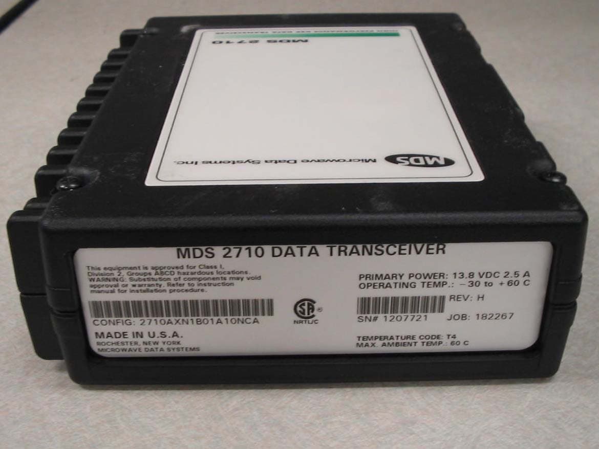
Click to zoom
Application Details
- Equipment Class
- TNB - Licensed Non-Broadcast Station Transmitter
- Date of Grant
- Oct 14, 2004
- Application Purpose
- Original Equipment
- Date of Application
- Oct 14, 2004
- Equipment Note
- Point to Point/Multipoint Wireless Modem
- Frequency Range
- 216.00000000 - 220.00000000
- Company
- GE MDS, LLC
- Country
- United States
Documents & Files
Document Text
Text extracted from the exhibit documents filed with the FCC. Open a document above to read the original.
Users Manual
Installation & Operation Guide MDS 05-3447A01, REV. F SEPTEMBER 2004 Data Transceiver Microwave Data Systems Inc. MDS 1710 A/C MDS 2710A/C/D QUICK START GUIDE Below are the basic steps for installing the transceiver. Detailed instructions are provided in “Installation Steps” on Page 9 of this manual. 1. Install and connect the antenna system to the radio • Use good quality, low loss coaxial cable. Keep the feedline as short as possible. • Preset directional antennas in the direction of desired transmission/reception. 2. Connect the data equipment to the radio’s INTERFACE connector • Connection to the radio must be made with a DB-25 Male connector. Connections for typical sys- tems are shown below. • Connect only the required pins. Do not use a straight-through RS-232 cable with all pins wired. • Verify the data equipment is configured as DTE. (By default, the radio is configured as DCE.) 3. Apply DC power to the radio (10.5–16 Vdc @ 2.5 A minimum) • Observe proper polarity. The red wire is the positive lead; the black is negative. 4. Set the radio’s basic configuration with a Hand-Held Terminal (HHT) • Set the transmit frequency ( TX xxx.xxxxx ). • Set the receive frequency ( RX xxx.xxxxx ). • Set/verify the data rate using the BAUD command. The default setting is BAUD 4800 8N1 . (Refer to “TRANSCEIVER PROGRAMMING” on Page 17 for command details.) 5. Verify proper operation by observing the LED display • Refer to Table 5 on Page 16 for a description of the status LEDs. • Refine directional antenna headings for maximum receive signal strength using the RSSI com- mand. DB-25DB-25 2 3 2 3 4 5 20 6DSR DSR 6 TXD RXD GND RTS CTS TXD RXD GND 4 CTS 5 RTS DB-9DB-25 DB-9 to DB-25 ExampleDB-25 to DB-25 Example 11 4 5 2 3 3 2 5 20 7 RXD TXD DCD GND DSR RTS RXD TXD DCD GND As required for application 5 18 7 6 CTS DSR RTS CTS8 6 4 5 77 GND GND 88 DCD DCD As required for application RTU (DTE) TRANSCEIVER (DCE) RTU (DTE) TRANSCEIVER (DCE) MDS 05-3447A01, Rev. FMDS 1710A/C and MDS 2710A/C/Di TABLE OF CONTENTS 1.0 GENERAL.................................................................................... 1 1.1 Introduction ...................................................................................... 1 1.2 Differences Between Models ........................................................... 2 1.3 Applications ...................................................................................... 2 Point-to-Multipoint, Multiple Address Systems (MAS) .................... 2 Point-to-Point System ..................................................................... 3 Continuously Keyed versus Switched Carrier Operation ................ 4 Single Frequency (Simplex) Operation ........................................... 4 1.4 Product Configurator Codes ............................................................. 4 1.5 Accessories ...................................................................................... 5 2.0 GLOSSARY OF TERMS.............................................................. 5 3.0 INSTALLATION ............................................................................ 8 3.1 Installation Steps .............................................................................. 9 3.2 Transceiver Mounting ..................................................................... 11 3.3 Antennas and Feedlines ................................................................ 11 Feedlines ...................................................................................... 12 3.4 Power Connection .......................................................................... 12 3.5 Data Interface Connections ............................................................ 13 3.6 Using the Radio’s Sleep Mode ....................................................... 13 Sleep Mode Example ................................................................... 13 4.0 OPERATION .............................................................................. 15 4.1 LED Indicators ................................................................................ 16 4.2 RSSI Measurement ........................................................................ 16 5.0 TRANSCEIVER PROGRAMMING ............................................ 17 5.1 Hand-Held Terminal Connection & Startup .................................... 17 5.2 Hand-Held Terminal Setup ............................................................. 18 5.3 Keyboard Commands ..................................................................... 19 Entering Commands ..................................................................... 19 Error Messages ............................................................................ 19 5.4 Detailed Command Descriptions ................................................... 22 AMASK [0000 0000–FFFF FFFF] ................................................ 22 ASENSE [HI/LO]........................................................................... 23 BAUD [xxxxx abc] ......................................................................... 23 BUFF [ON, OFF]........................................................................... 23 CKEY [ON–OFF] .......................................................................... 24 CTS [0–255] ................................................................................. 24 DATAKEY [ON, OFF] .................................................................... 24 DEVICE [DCE, CTS KEY] ............................................................ 24 DKEY ............................................................................................ 25 iiMDS 1710A/C and MDS 2710A/C/DMDS 05-3447A01, Rev. F DLINK [ON/OFF/xxxx] .................................................................. 25 DMGAP [xx] .................................................................................. 25 DTYPE [NODE/ROOT] ................................................................. 25 DUMP ...........…
Text truncated - open the document above for the full version.
Cover Letter(s)
Page 1 of 2 RE: Microwave Data Systems FCC ID: E5MDS-2710AC 1.) Please provide a Tune Up procedure for this device. Response: The MDS 2710 radio is a DSP based digital radio and there is no tune up procedure, the radio must be returned to the factory, so "TEST and ALIGNMENT" software can be uploaded to enable the factory/repair shop to retune the radio. There is not customer tune up. 2.) Please provide a Block Diagram of only the radio section for this product. Response: Block Diagram has been uploaded. 3.) FCC Part 2 requires the inclusion of E and I through the final amplifier circuit at full power. Please revise your report Response: Information has been included in the report. Voltage is +5Vdc, Current is 1amp 4.) From observing the occupied BW, it appears that F3E emissions should be considered. This was not requested on Form 731. Please review and advise. Response: Yes we would like the F3E designator on the grant. All the other MDS radios with similar topology are granted this way. 731 form and all relevant documents have been revised and uploaded. 5.) Kindly provide full justification for all requested emission designators. You have provided Carson’s Rule calculations for only one necessary bandwidth – please provide supporting documentation for all fundamental emissions, both analog and digital. Response: Explanation for each emission designator is included. Revised report has been uploaded. The 99% BW was used to determine the emission designator for the digital signal. The client could not provide information regarding the deviation and modulation, for the digital signal, at this time. 6.) It is not apparent if this device will be used indoors as well as outdoors on fixed permanent structures. Will this device be used exclusively outdoors? Please review and advise. Response: Yes 99% of our applications are for industrial customers with outdoor installations.. But there is chance that some of customers may decide to use this transceiver indoors in some form of industrial automation. We have no control on the end user. Examples could be, factory cart automation in a large warehouse. 7.) Could this device be considered a computer peripheral? If so, then either DofC or Part 15 Certification may apply. Response: It could be considered a computer peripheral, but intended use will be in industrial environments. So verification was performed instead of the DoC. 8.) Kindly identify each occupied bandwidth plot with it’s associated emission designator including necessary bandwidth. Response: Each plot has the emission designator. Revised report has been uploaded. 9.) FYI: There appear to be several discrepancies in the CFRs with regard to Part 90 equipment operating within the 216-220MHz band. Additional consultation with the Commission by AmericanTCB will be required. Please be patient. Response: Understood. Please let us know when you get a reply from FCC. Client is in a tight deadline. Regards, Juan Martinez Sr. EMC Engineer Page 2 of 2
Cover Letter(s)
Page 1 of 2 RE: Microwave Data Systems FCC ID: E5MDS-2710AC 1.) It appears the most applicable FCC Rule part for this device is 90.259. Do you concur with this finding? Response: Yes we concur. 2.) With your permission, I propose to call this device a “Point to Point/Multipoint Wireless Modem.” Is that acceptable to your client? Response: Yes this is indeed a wireless modem that is used in a point/multipoint applications 3.) With your permission, I will state the frequency tolerance on the Grant as 1ppm. It is not necessary to state the measured frequency tolerance on the Grant. Response: This will be fine with us. 4.) The FCC is usually very emphatic about having a tune-up procedure for any filing even when no user serviceable parts are accessible. This could be simply a tune up procedure for how it is adjusted on the factory floor. Of most interest to FCC is how this device will maintain its RF Pout. Kindly provide a tune up specification for this product. Please be advised that this can be held Confidential assuming it is listed in the Confidentiality Request letter. Response: The 2710AC radio is a DSP based digital radio modem that is software controlled and factory calibrated. When the radio requires any adjustment other than receiver helical tuning, the radio is returned to the factory where a comprehensive process is followed for calibrating. The radio is connected to a RS232 port, test and alignment software is loaded, then through a combination of LABVIEW software and MDS test and alignment software, the radio is calibrated. The tests include a wide array of IEEE bus driven equipment controlled from a host server, the radio's barcode is read and the software is automatically loaded, the barcode details all the radios settings from RX channel, TX channel, RF power settings, Modem settings etc. Once the radio configuration is read, the local computer gathers all the data and writes it to server for future reference. The only factory adjustable part in the entire radio is the receiver front end helical filter, and this is tuned by the test operator for best receiver sensitivity on channel. The RF power is calibrated using a forward power detector on the PCB, this voltage is logged and stored in the Micro, so the according "A to D" value reflects a particular RF power setting. Typically all the SCADA radios we manufacture calibrate from +20 to +37dBm in 1 dB steps. So a typical value might be FPWR (forward power) 255 will equal +37dBm etc. This is all stored and referenced and thus the RF power is constantly under a forward, closed loop power control. All this information is stored in the Micro on the radio, then the final customer configuration is set and the radio is shipped. This above information is not required to listed as confidential. Page 2 of 2 5.) FYI: In my research, I found just a few products which utilize this frequency band under Part 90. Several applicants submitted Transient Frequency Response data as a part of this filing. Although not specifically called out in the technical standards for Part 90, kindly be aware that this data may be requested. It may be prudent to perform this test and make it available as a supplement to this filing. Response: Understood. We will perform the transient measurements just in case FCC does ask for them. Please proceed with the application and grant while we set the time to schedule the transient test. 6.) In response to your answer to my question #6 from my October 1 questions, the Grant Notes will specifically state that this device will be limited to outdoor use only on permanent structures. Indoor use will be prohibited. If indoor use is sought, then a more comprehensive indoor installation procedure must be included. Response: Right now outdoor use is typical, the 220MHz band is not generally used indoors, and if it is, usually a omni unity gain antenna is used. In this case all the FCC radiation hazards must be met and the MPE safety distances must be figured according to transmit power. With a 2 watt radio, with a 0 gain antenna, and a 50% duty cycle, at 216MHz, the RF safety distance is only 11 inches. This can easily be met in a typical roaming cart application. We have no control over the end user/installer and their application, but we can distribute RF safety literature with the radio in this case, I referenced above. If the device is used indoors we will ensure the FCC MPE/RF Safety guideline information is distributed to proper personnel. If the above generic information is not good enough to satisfy the TCB for indoor installation, then it is OK to list the grant as outdoor installation only. Also if we have a customer in the future that wants to use this at a indoor factory we will have to file class 2 change to allow indoor installation. Regards, Juan Martinez Sr. EMC Engineer
Cover Letter(s)
American Telecommunications Certification Body Inc. 6731 Whittier Ave, McLean, VA 22101 October 1, 2004 RE: Microwave Data Systems FCC ID: E5MDS-2710AC I have a few comments on this Application. Depending on your responses, kindly understand there may be additional comments. 1.) Please provide a Tune Up procedure for this device. 2.) Please provide a Block Diagram of only the radio section for this product. 3.) FCC Part 2 requires the inclusion of E and I through the final amplifier circuit at full power. Please revise your report 4.) From observing the occupied BW, it appears that F3E emissions should be considered. This was not requested on Form 731. Please review and advise. 5.) Kindly provide full justification for all requested emission designators. You have provided Carson’s Rule calculations for only one necessary bandwidth – please provide supporting documentation for all fundamental emissions, both analog and digital. 6.) It is not apparent if this device will be used indoors as well as outdoors on fixed permanent structures. Will this device be used exclusively outdoors? Please review and advise. 7.) Could this device be considered a computer peripheral? If so, then either DofC or Part 15 Certification may apply. 8.) Kindly identify each occupied bandwidth plot with it’s associated emission designator including necessary bandwidth. 9.) FYI: There appear to be several discrepancies in the CFRs with regard to Part 90 equipment operating within the 216-220MHz band. Additional consultation with the Commission by AmericanTCB will be required. Please be patient. William H. Graff President and Director of Engineering mailto: [email protected] The items indicated above must be submitted before processing can continue on the above referenced application. Failure to provide the requested information may result in application termination. Correspondence should be considered part of the permanent submission and may be viewed from the Internet after a Grant of Equipment Authorization is issued. Please do not respond to this correspondence using the email reply button. In order for your response to be processed expeditiously, you must submit your documents through the AmericanTCB.com website. Also, please note that partial responses increase processing time and should not be submitted. Any questions about the content of this correspondence should be directed to the sender.
Cover Letter(s)
American Telecommunications Certification Body Inc. 6731 Whittier Ave, McLean, VA 22101 October 13, 2004 RE: Microwave Data Systems FCC ID: E5MDS-2710AC I have just a couple additional comments on this Application. Depending on your responses, kindly understand there may be additional comments. Cheer up – we’re almost ready. 1.) It appears the most applicable FCC Rule part for this device is 90.259. Do you concur with this finding? 2.) With your permission, I propose to call this device a “Point to Point/Multipoint Wireless Modem.” Is that acceptable to your client? 3.) With your permission, I will state the frequency tolerance on the Grant as 1ppm. It is not necessary to state the measured frequency tolerance on the Grant. 4.) The FCC is usually very emphatic about having a tune-up procedure for any filing even when no user serviceable parts are accessible. This could be simply a tune up procedure for how it is adjusted on the factory floor. Of most interest to FCC is how this device will maintain its RF Pout. Kindly provide a tune up specification for this product. Please be advised that this can be held Confidential assuming it is listed in the Confidentiality Request letter. 5.) FYI: In my research, I found just a few products which utilize this frequency band under Part 90. Several applicants submitted Transient Frequency Response data as a part of this filing. Although not specifically called out in the technical standards for Part 90, kindly be aware that this data may be requested. It may be prudent to perform this test and make it available as a supplement to this filing. 6.) In response to your answer to my question #6 from my October 1 questions, the Grant Notes will specifically state that this device will be limited to outdoor use only on permanent structures. Indoor use will be prohibited. If indoor use is sought, then a more comprehensive indoor installation procedure must be included. William H. Graff President and Director of Engineering mailto: [email protected] The items indicated above must be submitted before processing can continue on the above referenced application. Failure to provide the requested information may result in application termination. Correspondence should be considered part of the permanent submission and may be viewed from the Internet after a Grant of Equipment Authorization is issued. Please do not respond to this correspondence using the email reply button. In order for your response to be processed expeditiously, you must submit your documents through the AmericanTCB.com website. Also, please note that partial responses increase processing time and should not be submitted. Any questions about the content of this correspondence should be directed to the sender.
RF Exposure Info
MPE Exposure Formula: S = ( P X G ) / ( 4 X π X d^2 ) where: S = power density P = transmitter conducted power in (mW) G = antenna numeric gain d = distance to radiation center (m) or (.02^2 ) = .020 m Gain =8Numeric9.2dBi Power = 1995mW33dBm Frequency =216MHz0.200 mW/cm^2 Cable Loss =0dB EIRP =16595.87mW16595.87mW R (cm) = S (20cm) = Note: Enter Data in Linear Units 3.30281.2606085 Microwave Data Systems will be using different antennas so only the highest gain antenna to be used with transmitter is stated. For worse case scenario this does not include any cable loss.
Test Report
File: R57075 September 8, 2004 ATCB 6731 Whittier Ave Suite C110 McLean, Va. 22101 Gentlemen: The enclosed documents constitute a formal submittal and request for a Certification pursuant to Part 90 of FCC Rules (CFR 47) regarding to Public Mobile Service. Certification is being requested for Microwave Data Systems model MDS2710A/C. The MDS2710A/C has been tested and found to comply with FCC Part 90 limits. Elliott Laboratories, as duly authorized agent prepared this submittal. A copy of the letter of our appointment as agent is enclosed. If there are any questions or if further information is needed, please contact Elliott Laboratories for assistance. Sincerely, Juan Martinez Senior EMC Engineer JM/dmg Enclosures: Agent Authorization Letter Confidentiality Letter Schematics External and Internal Photos Manual Theory of Operations FCC ID Label and Location Emissions Test Report with Exhibits File: R57075 September 8, 2004 Industry Canada, Certification Section Certification and Engineering Bureau 1241 Clyde Avenue Ottawa, Canada K2C 1Y3 Gentlemen: The enclosed documents constitute a formal submittal and request for a Certification pursuant to RSS-119, Issue 6 (Land Mobile and Fixed Radio Transmitters and Receivers, 27.41 to 960 MHz). Certification is being requested for Microwave Data Systems model MDS2710A/C. The MDS2710A/C has been tested and found to comply with RSS-119, issue 6 limits. Elliott Laboratories, as duly authorized agent prepared this submittal. A copy of the letter of our appointment as agent is enclosed. If there are any questions or if further information is needed, please contact Elliott Laboratories for assistance. Sincerely, Juan Martinez Senior EMC Engineer JM/dmg Enclosures: Schematics External and Internal Photos Manual Theory of Operations Label and Location Emissions Test Report with Exhibits File: R57075 Page 1 of 19 Electromagnetic Emissions Test Report In Accordance With Industry Canada Radio Standards Specification 119 Issue 6, FCC Part 90 on the Microwave Data Systems Transmitter Model: MDS2710A/C FCC ID NUMBER: E5MDS-2710AC UPN: 3738A-2710AC GRANTEE: Microwave Data Systems 175 Science Parkway Rochester, NY 14620 TEST SITE: Elliott Laboratories, Inc. 41039 Boyce Road Fremont, CA 41039 REPORT DATE: September 8, 2004 FINAL TEST DATE: August 27, August 28, August 30 and August 31, 2004 AUTHORIZED SIGNATORY: ______________________________ Juan Martinez Senior EMC Engineer Elliott Laboratories, Inc. is accredited by the A2LA, certificate number 2016-01, to perform the test(s) listed in this report. This report shall not be reproduced, except in its entirety, without the written approval of Elliott Laboratories, Inc. Elliott Laboratories, Inc. -- EMC Department Test Report Report Date: September 8, 2004 TABLE OF CONTENTS COVER PAGE.............................................................................................................................................................1 TABLE OF CONTENTS..........................................................................................................................................2 FCC CERTIFICATION INFORMATION.............................................................................................................3 DECLARATIONS OF COMPLIANCE..................................................................................................................5 SCOPE........................................................................................................................................................................6 OBJECTIVE..............................................................................................................................................................6 SUMMARY OF TEST RESULTS...........................................................................................................................7 PART 90 AND RSS-119 TEST SUMMARY.............................................................................................................7 MEASUREMENT UNCERTAINTIES...................................................................................................................8 EQUIPMENT UNDER TEST (EUT) DETAILS....................................................................................................9 GENERAL..............................................................................................................................................................9 ENCLOSURE.........................................................................................................................................................9 MODIFICATIONS.................................................................................................................................................9 SUPPORT EQUIPMENT.....................................................................................................................................10 EUT INTERFACE PORTS..................................................................................................................................10 EUT OPERATION DURING TESTING.............................................................................................................10 TEST SITE...............................................................................................................................................................11 GENERAL INFORMATION...............................................................................................................................11 CONDUCTED EMISSIONS CONSIDERATIONS............................................................................................11 RADIATED EMISSIONS CONSIDERATIONS................................................................................................11 MEASUREMENT INSTRUMENTATION..........................................................................................................12 RECEIVER SYSTEM...............…
Text truncated - open the document above for the full version.
Contact Information
Applicant
John Barenys(Senior Operations Manager)
Technical Contact
Elliott Laboratories, IncJuan Martinez
[email protected]408 245 7800
684 W. Maude Avenue · Sunnyvale, California · United States
Test Firm
Elliott Laboratories LLCDavid Bare
Technical Specifications
| # | Rule Parts | Frequency Range | Power Output | Emission | Tolerance |
|---|---|---|---|---|---|
| 6 | 90.259 | 216 MHz - 220 MHz | 2 W | 11K0F3E | 1 ppm |
Other Applications from GE MDS, LLC

E5MDS-NET9S
Jul 13, 2023Frequency Hopping Radio
Equipment Class
DSS - Part 15 Spread Spectrum Transmitter
E5MDS-NET9L
Jul 11, 2023Frequency Hopping Radio
Equipment Class
DSS - Part 15 Spread Spectrum Transmitter
E5MDS-LN900
Jan 27, 2016Industrial Radio Module
Equipment Class
TNB - Licensed Non-Broadcast Station Transmitter
E5MDS-SDM4
Aug 20, 2015MDS SDM4 Licensed Spectrum Module
Equipment Class
TNB - Licensed Non-Broadcast Station Transmitter
E5MDS-LN400
Jul 09, 2015Industrial Radio Module
Equipment Class
TNB - Licensed Non-Broadcast Station Transmitter