E5MDS-9810Spread Spectrum Data Tranceiver
GE MDS, LLC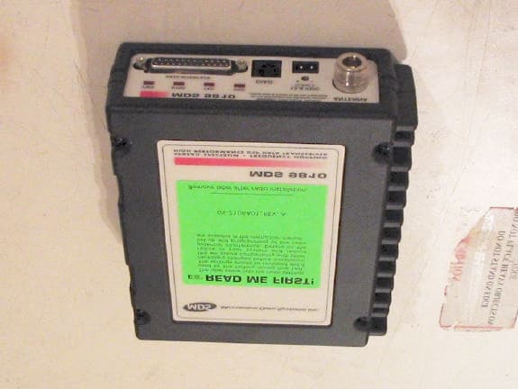
Click to zoom
Application Details
- Equipment Class
- DSS - Part 15 Spread Spectrum Transmitter
- Date of Grant
- Jul 28, 2004
- Application Purpose
- Original Equipment
- Date of Application
- Jul 28, 2004
- Equipment Note
- Spread Spectrum Data Tranceiver
- Frequency Range
- 902.20000000 - 927.80000000
- Company
- GE MDS, LLC
- Country
- United States
Documents & Files
Document Text
Text extracted from the exhibit documents filed with the FCC. Open a document above to read the original.
Users Manual
MDS 05-3301A01, Rev. CMDS 9810 Installation and Operation Guideiii TABLE OF CONTENTS 1.0 ABOUT THIS MANUAL ............................................................... 1 2.0 PRODUCT DESCRIPTION ......................................................... 1 Transceiver Features ...................................................................... 2 Model Configuration Codes ............................................................ 2 2.1 Spread Spectrum Radios—How Are They Different? ...................... 3 2.2 Typical Applications .......................................................................... 3 Multiple Address Systems (MAS) ................................................... 3 Simplex “Peer-to-Peer” ................................................................... 4 Peer-to-Peer with Repeater Assistance .......................................... 5 Point-to-Point System ..................................................................... 5 Tail-End Link (“MAS Extension”)..................................................... 6 Repeater Arrangement ................................................................... 6 2.3 Accessories ...................................................................................... 7 3.0 GLOSSARY OF TERMS.............................................................. 8 4.0 INSTALLATION PLANNING....................................................... 11 4.1 General Requirements ................................................................... 11 4.2 Site Selection ................................................................................. 12 Terrain and Signal Strength .......................................................... 12 Conducting a Site Survey ............................................................. 13 4.3 A Word About Radio Interference .................................................. 13 4.4 Antenna & Feedline Selection ........................................................ 15 Antennas ...................................................................................... 15 Feedlines ...................................................................................... 17 4.5 How Much Power Can I Run? ........................................................ 18 For All MDS 9810 Systems........................................................... 18 For MAS Point-to-Multipoint Systems (MDS 24810)..................... 19 For Point-to-Point Systems (MDS 24810)..................................... 20 5.0 INSTALLATION .......................................................................... 22 5.1 Transceiver Installation ................................................................... 23 5.2 Peer-to-Peer Systems .................................................................... 26 Simplex Peer-to-Peer.................................................................... 27 Peer-to-Peer with Repeater Assistance ........................................ 27 5.3 Tail-End Links ................................................................................. 29 5.4 Repeaters ....................................................................................... 30 5.5 Using the Radio’s Sleep Mode ....................................................... 31 System Example........................................................................... 31 MDS 05-3301A01, Rev. CMDS 9810 Installation and Operation Guideiv 6.0 OPERATION .............................................................................. 32 6.1 Initial Start-up ................................................................................. 32 6.2 Performance Optimization .............................................................. 33 Antenna Aiming ............................................................................ 33 Antenna SWR Check.................................................................... 33 Data Buffer Setting ....................................................................... 34 Hoptime Setting ............................................................................ 34 Baud Rate Setting ........................................................................ 34 Radio Interference Checks ........................................................... 34 7.0 PROGRAMMING....................................................................... 35 7.1 Hand-Held Terminal Connection & Start-up ................................... 35 7.2 Hand-Held Terminal Setup ............................................................. 36 7.3 Keyboard Commands ..................................................................... 37 Entering Commands ..................................................................... 37 Error Messages ............................................................................ 37 7.4 Detailed Command Descriptions ................................................... 41 ADDR [1...65000] ......................................................................... 41 AMASK [0000 0000–FFFF FFFF] ................................................ 42 ASENSE [HI/LO]........................................................................... 42 BAUD [xxxxx abc] ......................................................................... 42 BUFF [ON, OFF]........................................................................... 43 CTS [0–255] ................................................................................. 43 CTSHOLD [0-6000] ...................................................................... 44 DEVICE [DCE, CTS KEY] ............................................................ 44 DLINK [xxxxx] ............................................................................... 44 DMGAP [xx] .................................................................................. 45 DTYPE [NODE/ROOT/GATE/PEER] ............................................ 45 HOPTIME [XSHORT, SHORT, NORMAL, LONG] ........................ 45 I…
Text truncated - open the document above for the full version.
Users Manual
Installation and Operation Guide Installation & Operation Guide MDS 05-3301A01, Rev. C JULY 2004 900 MHz Spread Spectrum Data Transceivers Microwave Data Systems Inc. MDS 9810 QUICK START GUIDE Below are the basic steps for installing the transceiver. Detailed instructions are given in “INSTALLA- TION” on Page 14 of this guide. 1. Install and connect the antenna system to the radio •Use good quality, low-loss coaxial cable. Keep the feedline as short as possible. •Preset directional antennas in the direction of desired transmission. 2. Connect the data equipment to the radio’s INTERFACE connector •Connection to the radio must be made with a DB-25 Male connector. Connections for typical systems are shown below. •Connect only the required pins. Do not use a straight-through RS-232 cable with all pins wired. •Verify the data equipment is configured as DTE. (By default, the radio is configured as DCE.) 3. Apply DC power to the radio •Observe proper polarity. The red wire is the positive lead; the black is negative. 4. Set the radio’s basic configuration with a Hand-Held Terminal (HHT) • Set the baud rate/data interface parameters as follows. Use the BAUD xxxxx abc command, where xxxxx equals the data speed and abc equals the communication parameters as follows: a = Data bits (7 or 8) b = Parity (N for None, O for Odd, E for Even c = Stop bits (1 or 2) (Example: BAUD 9600 8N1 ) NOTE: 7N1, 8E2 and 8O2 are invalid parameters and are not supported by the transceiver. 5. Verify proper operation by observing the LED display •Refer to Table 4 on Page 26 for a description of the status LEDs. •Refine directional antenna headings for best received signal strength using the RSSI command. DB-25DB-25 2 3 2 3 4 5 20 6DSR DSR 6 TXD RXD GND RTS CTS TXD RXD GND 4 CTS 5 RTS DB-9DB-25 DB-9 to DB-25 ExampleDB-25 to DB-25 Example 11 4 5 2 3 3 2 5 20 7 RXD TXD DCD GND DSR RTS RXD TXD DCD GND As required for application 5 18 7 6 CTS DSR RTS CTS8 6 4 5 77 GND GND 88 DCD DCD As required for application RTU (DTE) TRANSCEIVER (DCE) RTU (DTE) TRANSCEIVER (DCE) MDS 05-3301A01, Rev. CMDS 9810 Installation and Operation Guidei TABLE OF CONTENTS 1.0 ABOUT THIS MANUAL.........................................................................................................1 2.0 PRODUCT DESCRIPTION................................................................................................... 1 Transceiver Features........................................................................................................................ 2 Model Configuration Codes ............................................................................................................. 2 2.1 Spread Spectrum Radios—How Are They Different? .................................................................... 3 2.2 Typical Applications ....................................................................................................................... 3 Multiple Address Systems (MAS) .................................................................................................... 3 Simplex “Peer-to-Peer”..................................................................................................................... 4 Peer-to-Peer with Repeater Assistance ...........................................................................................4 Point-to-Point System....................................................................................................................... 5 Tail-End Link (“MAS Extension”) ...................................................................................................... 5 Repeater System—Traditional ......................................................................................................... 6 “Single-Radio” Repeater—Alternative Method................................................................................. 6 2.3 Accessories ................................................................................................................................... 7 3.0 INSTALLATION PLANNING .................................................................................................. 7 3.1 General Requirements .................................................................................................................. 7 3.2 Site Selection ................................................................................................................................ 8 Terrain and Signal Strength ............................................................................................................. 9 Conducting a Site Survey ................................................................................................................ 9 3.3 A Word About Radio Interference ................................................................................................ 10 3.4 Antenna & Feedline Selection ..................................................................................................... 11 Antennas........................................................................................................................................ 11 Feedlines ....................................................................................................................................... 12 3.5 How Much Output Power Can be Used? ..................................................................................... 13 Transmitter Power vs. Antenna System Gain ................................................................................. 13 4.0 INSTALLATION ................................................................................................................... 14 4.1 Transceiver Installation ................................................................................................................ 15 4.2 Peer-to-Peer Systems ................................................................................................................. 19 Si…
Text truncated - open the document above for the full version.
Cover Letter(s)
175 Science Parkway, Rochester, New York 14620 USA (585) 242-9600 Phone (585) 242-9620 Fax July 15, 2004 FEDERAL COMMUNICATIONS COMMISSION 7435 Oakland Mills Road Columbia, MD 21046 U.S.A. Subject: Request for withholding from public disclosure the schematic diagrams and system block diagrams pursuant to an application for certification. Applicant: Microwave Data Systems Inc. Product: MDS9810, 902-928MHz FHSS Data Transceiver Model: MDS9810 FCC ID: E5MDS-9810 Dear Sir/Madam, We, Microwave Data Systems Inc., would like to request that the schematic diagrams, system block diagram, Theory of Operation and Bill of Materials submitted with the application for certification be withheld from public disclosure as per Section 0.459 of FCC Rules. This request is made under the provisions of Section 0.457(d) of the Commission's Rules, and Section 552(b)(4) of the Freedom of Information Act. These sections authorize as a withholding from public inspection materials which would be privileged as a matter of law if retained by the person submitting them, and materials which would not customarily be released to the public by that person. If you have any queries, please do not hesitate to contact me at 585 242-8440: Yours truly, Dennis McCarthy Agency Compliance Engineer Microwave Data Systems 175 Science Parkway Rochester NY 14620 Phone (585) 242-8440 Email [email protected]
Cover Letter(s)
175 Science Parkway, Rochester, New York 14620 USA (585) 242-9600 Phone (585) 242-9620 Fax July 15th, 2004 FEDERAL COMMUNICATIONS COMMISSION 7435 Oakland Mills Road Columbia, MD 21046 U.S.A. Subject: Authority to Act as an Agent to FCC Applicant: Microwave Data Systems Inc. Product: MDS9810, 902-928MHz FHSS Data Transceiver Model: MDS9810 FCC ID: E5MDS-9810 Dear Sir/Madam, I hereby appoint Elliott Labs of Sunnyvale Calif. to act as my agent in preparation of this application to F.C.C. for authorization of equipment under F.C.C. Rules. I also certify that the information provided, properly described the device or system for which authorization is required. If you have any queries, please do not hesitate to contact me at 585 242-8440: Yours truly, Dennis McCarthy Agency Compliance Engineer Microwave Data Systems 175 Science Parkway Rochester NY 14620 Phone (585) 242-8440 Email [email protected]
Cover Letter(s)
American Telecommunications Certification Body Inc. 6731 Whittier Ave, McLean, VA 22101 July 26, 2004 RE: FCC ID: E5MDS-9810_ATCB001525 Attention: Juan Martinez I have a few comments on this Application. Please note that further comments may arise in response to answers provided to the questions below. 1. FYI - Please note that the MPE report states 0.020cm for d. This should be 0.020 m or 20cm. Please also note that the MPE report shows that antenna with greater gain than 10dBi require more than 20cm separation. Please address this issue. 2. Please note that the first table in the MPE report uses a frequency of 1500MHz. Please note that this device operates in the 902 to 928 MHz range – thus giving an r of 10cm.. Please provide an MPE report which addresses the frequency range of the device. 3. Please note that it does not appear that the manual addresses the minimum separation distance between the antenna and the user. Please address this issue in the manual and please be consistent with other documentation. 4. Please note that at the frequencies of concern, cardboard may not be the best or idea material for support of the antenna. Please justify and/or explain what measures were taken to verify that the cardboard box had no adverse affects on the readings for spurious emissions. Please note that a more appropriate material may be Styrofoam supports. 5. Please provide a hop table showing the pseudo random nature of the hop sequence. IC 6. Please note that the RSP100 form indicates that the power is a step function. This would also indicate that minimum and maximum power level existed. Please note that you have not provided a minimum power level for this device. Please explain, or alternately please provide the measured minimum power level for the device. Dennis Ward mailto:[email protected] The items indicated above must be submitted before processing can continue on the above referenced application. Failure to provide the requested information may result in application termination. Correspondence should be considered part of the permanent submission and may be viewed from the Internet after a Grant of Equipment Authorization is issued. Please do not respond to this correspondence using the email reply button. In order for your response to be processed expeditiously, you must submit your documents through the AmericanTCB.com website. Also, please note that partial responses increase processing time and should not be submitted. Any questions about the content of this correspondence should be directed to the sender.
Cover Letter(s)
Page 1 of 1 RE: FCC ID: E5MDS-9810_ATCB001525 1. FYI - Please note that the MPE report states 0.020cm for d. This should be 0.020 m or 20cm. Please also note that the MPE report shows that antenna with greater gain than 10dBi require more than 20cm separation. Please address this issue. Response: The MPE report has been corrected. 2. Please note that the first table in the MPE report uses a frequency of 1500MHz. Please note that this device operates in the 902 to 928 MHz range – thus giving an r of 10cm.. Please provide an MPE report which addresses the frequency range of the device. Response: The extra table was just an example and has no meaning to what was tested. This example table was removed and a revised MPE has been uploaded. 3. Please note that it does not appear that the manual addresses the minimum separation distance between the antenna and the user. Please address this issue in the manual and please be consistent with other documentation. Response: The manual provided was the original manual used for similar past approved MDS9810. For this reason a portion of that manual was uploaded to the RF Exposure exhibit. This portion will show the minimum separation, which the MPE calculated to be 22cm. This portion of the manual has been uploaded to the Manual exhibit instead, for your review. 4. Please note that at the frequencies of concern, cardboard may not be the best or idea material for support of the antenna. Please justify and/or explain what measures were taken to verify that the cardboard box had no adverse affects on the readings for spurious emissions. Please note that a more appropriate material may be Styrofoam supports. Response: Justification was done by measuring the fundamental at 3 meters. The Calculated values yield a field strength of 130.7 dBuV/m @ 3 meters at 928 MHz. A measured value at 3 meters for 928 MHz yield a field strength of 128.4 dBuV/m. The difference is only 2.5 dB which could be cause by the Yagi not having a true 10dBi gain at the frequency, cable loss, and measurement uncertainty. But, it is still within the site’s +/- 4dB deviation. For future tests we will use Styrofoam. Calculated Frequency Power Gain EIRP EIRP (MHz) (dBm) (dBi) (dBm) (dBuV/m) 902 25.6 10.0 35.6 130.9 928 25.4 10.0 35.4 130.7 Measured @ 3 meters Frequency EIRP (MHz) (dBuV/m) 902 127.4 928 128.2 Page 2 of 2 5. Please provide a hop table showing the pseudo random nature of the hop sequence. Response: Hopping sequence has been uploaded. IC 6. Please note that the RSP100 form indicates that the power is a step function. This would also indicate that minimum and maximum power level existed. Please note that you have not provided a minimum power level for this device. Please explain, or alternately please provide the measured minimum power level for the device. Response: RSP-100 form has been revised with the minimum power level of the lowest setting. Regards, Juan Martinez Sr. EMC Engineer
Cover Letter(s)
Mr. Dennis Ward, Subject: Amendment of power to FCC and IC grants Applicant: Microwave Data Systems Inc. Model: MDS9810 FCC ID: E5MDS-9810 The following amendment is requested to be made to the grant: 1) Power change, on grants, from .363 to .955 Watts. Report and new data has been included to reflect change in power. MPE calculation, 731 form, and RSP-100 form have all been revised to reflect new power. 2) Client will like the following statement on the grant, if possible: “antenna(s) of lower gain and in the same family Yagi or Omni are type approved for use” Regards, Juan Martinez Sr. EMC Engineer
RF Exposure Info
MPE Exposure Formula: S = ( P X G ) / ( 4 X π X d^2 ) where: S = power density P = transmitter conducted power in (mW) G = antenna numeric gain d = distance to radiation center (m) or (.02^2 ) = .020 m Gain =10Numeric10dBi Power = 391mW26dBm Frequency =902MHz0.601 mW/cm^2 Cable Loss =0.08dB EIRP =3908.41mW3908.41mW R (cm) = S (20cm) = Gain =10Numeric10dBi Power = 391mW26dBm Frequency =915MHz0.610 mW/cm^2 Cable Loss =0.08dB EIRP =3908.41mW3908.41mW R (cm) = S (20cm) = Gain =10Numeric10dBi Power = 391mW26dBm Frequency =928MHz0.619 mW/cm^2 Cable Loss =0.08dB EIRP =3908.41mW3908.41mW R (cm) = S (20cm) = Enter Data in Linear Units Enter Data in Linear Units Enter Data in Linear Units 0.778 0.778 22.7424594 22.5803230 0.77822.4216056 Gain =5Numeric7dBi Power = 398mW26dBm Frequency =902MHz0.601 mW/cm^2 Cable Loss =0dB EIRP =1995.26mW1995.26mW R (cm) = S (20cm) = Gain =5Numeric7dBi Power = 794mW29dBm Frequency =915MHz0.610 mW/cm^2 Cable Loss =0dB EIRP =3981.07mW3981.07mW R (cm) = S (20cm) = Gain =5Numeric7dBi Power = 794mW29dBm Frequency =928MHz0.619 mW/cm^2 Cable Loss =0dB EIRP =3981.07mW3981.07mW R (cm) = S (20cm) = Enter Data in Linear Units 16.24940370.397 22.62907020.792 Enter Data in Linear Units 22.78925620.792 Enter Data in Linear Units
Test Report
File: R56430 Page 1 of 18 Electromagnetic Emissions Test Report and Application for Grant of Equipment Authorization pursuant to FCC Part 15, Subpart C (15.247) FHSS Specifications and Industry Canada RSS 210 Issue 5 for an Intentional Radiator on the Microwave Data Systems Model: MDS9810 FCC ID: E5MDS-9810 UPN: 3738A-MDS9810 GRANTEE: Microwave Data Systems 175 Science Parkway Rochester, NY 14620 TEST SITE: Elliott Laboratories, Inc. 684 W. Maude Avenue Sunnyvale, CA 94086 REPORT DATE: July 19, 2004 FINAL TEST DATE: July 16 and July 17, 2004 AUTHORIZED SIGNATORY: _______________________ Juan Martinez Sr. EMC Engineer Elliott Laboratories, Inc. is accredited by the A2LA, certificate number 2016-01, to perform the test(s) listed in this report. This report shall not be reproduced, except in its entirety, without the written approval of Elliott Laboratories, Inc. Elliott Laboratories, Inc. -- EMC Department Test Report Report Date: July 19, 2004 File: R56430 Page 2 of 18 pages TABLE OF CONTENTS TABLE OF CONTENTS...............................................................................................................................................................2 SCOPE.............................................................................................................................................................................................3 OBJECTIVE...................................................................................................................................................................................3 SUMMARY OF RESULTS...........................................................................................................................................................4 MEASUREMENT UNCERTAINTIES....................................................................................................................................6 EQUIPMENT UNDER TEST (EUT) DETAILS..........................................................................................................................7 GENERAL...................................................................................................................................................................................7 ENCLOSURE..............................................................................................................................................................................7 MODIFICATIONS....................................................................................................................................................................7 SUPPORT EQUIPMENT..........................................................................................................................................................7 EUT INTERFACE PORTS........................................................................................................................................................8 EUT OPERATION DURING TESTING..................................................................................................................................8 ANTENNA REQUIREMENTS................................................................................................................................................8 TEST SITE......................................................................................................................................................................................9 GENERAL INFORMATION....................................................................................................................................................9 CONDUCTED EMISSIONS CONSIDERATIONS................................................................................................................9 RADIATED EMISSIONS CONSIDERATIONS....................................................................................................................9 MEASUREMENT INSTRUMENTATION................................................................................................................................10 RECEIVER SYSTEM...............................................................................................................................................................10 INSTRUMENT CONTROL COMPUTER............................................................................................................................10 LINE IMPEDANCE STABILIZATION NETWORK (LISN).............................................................................................10 POWER METER......................................................................................................................................................................11 FILTERS/ATTENUATORS...................................................................................................................................................11 ANTENNAS............................................................................................................................................................................11 ANTENNA MAST AND EQUIPMENT TURNTABLE....................................................................................................11 INSTRUMENT CALIBRATION...........................................................................................................................................11 TEST PROCEDURES.................................................................................................................................................................12 EUT AND CABLE PLACEMENT.........................................................................................................................................12 CONDUCTED EMISSIONS...................................................................................................................................................12 RADIATED EMISSIONS............................................................…
Text truncated - open the document above for the full version.
Contact Information
Applicant
John Barenys(Senior Operations Manager)
Technical Contact
Elliott Laboratories Inc.Juan Martinez
[email protected]408-245-7800
684 West Maude Ave. · Sunnyvale, California · United States
Test Firm
Element Materials Technology Fremont NewarkDavid Bare
Technical Specifications
| # | Rule Parts | Frequency Range | Power Output |
|---|---|---|---|
| 1 | 15C | 902.2 MHz - 927.8 MHz | 955.00 mW |
Other Applications from GE MDS, LLC

E5MDS-NET9S
Jul 13, 2023Frequency Hopping Radio
Equipment Class
DSS - Part 15 Spread Spectrum Transmitter
E5MDS-NET9L
Jul 11, 2023Frequency Hopping Radio
Equipment Class
DSS - Part 15 Spread Spectrum Transmitter
E5MDS-LN900
Jan 27, 2016Industrial Radio Module
Equipment Class
TNB - Licensed Non-Broadcast Station Transmitter
E5MDS-SDM4
Aug 20, 2015MDS SDM4 Licensed Spectrum Module
Equipment Class
TNB - Licensed Non-Broadcast Station Transmitter
E5MDS-LN400
Jul 09, 2015Industrial Radio Module
Equipment Class
TNB - Licensed Non-Broadcast Station Transmitter