E5MDS-CW500CarrierWave 500
GE MDS, LLC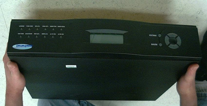
Click to zoom
Application Details
- Equipment Class
- DTS - Digital Transmission System
- Date of Grant
- Mar 16, 2003
- Application Purpose
- Original Equipment
- Date of Application
- Mar 16, 2003
- Equipment Note
- CarrierWave 500
- Frequency Range
- 5731.30000000 - 5843.70000000
- Company
- GE MDS, LLC
- Country
- United States
Documents & Files
Document Text
Text extracted from the exhibit documents filed with the FCC. Open a document above to read the original.
Users Manual
CarrierComm CarrierWave-100/155 User Reference and Installation Manual Document Number: MK-MAN-01 Rev: B Date: 11 March 2003 MK-MAN-01 CarrierWave Digital Radio CarrierWave Digital Radio Manual Dwg # MK-MAN-01; Revision Levels: A SectionDrawing No:REVRevised / Released Reason CW-100 CW-155 MK-MAN-01ASNInitial Release BAdded antenna professional installation and FCC clarification statements. CarrierWave Digital Radio MK-MAN-01 Table of Contents 1SAFETY PRECAUTIONS.............................................................................................................1-1 2SYSTEM DESCRIPTION..............................................................................................................2-1 2.1About This Manual...........................................................................................................................................................2-1 2.2Introduction........................................................................................................................................................................2-1 2.3System Features.................................................................................................................................................................2-4 2.4Physical Description..........................................................................................................................................................2-5 2.4.1Model Types...............................................................................................................................................................2-5 2.4.2Front Panel Indicators................................................................................................................................................2-6 2.4.3Rear Panel Connections............................................................................................................................................2-8 2.5System Description.........................................................................................................................................................2-10 2.6Consecutive Point Architecture..................................................................................................................................2-12 2.7Power Management........................................................................................................................................................2-15 2.8CarrierWave iWare TM Software and Network Management............................................................................2-16 3INSTALLATION...........................................................................................................................3-1 3.1Unpacking............................................................................................................................................................................3-1 3.2Notices..................................................................................................................................................................................3-2 3.3PRE-INSTALLATION NOTES....................................................................................................................................3-2 3.3.1Back-to-Back Bench Testing....................................................................................................................................3-2 3.4Overview of Installation and Testing Process...........................................................................................................3-3 3.5Site Evaluation....................................................................................................................................................................3-5 3.5.1Preparing for a Site Evaluation................................................................................................................................3-5 3.5.2Site Evaluation Process.............................................................................................................................................3-6 3.5.3Critical System Calculations....................................................................................................................................3-8 3.5.4Documenting a Site Evaluation..............................................................................................................................3-11 3.6Installation of the CarrierWave Digital Radio.......................................................................................................3-14 3.6.1Installing the CarrierWave IDU.............................................................................................................................3-14 3.6.2Installing the CarrierWave ODU............................................................................................................................3-15 3.6.3Routing the ODU/IDU Interconnect Cable..........................................................................................................3-20 3.6.4Grounding the System.............................................................................................................................................3-21 3.7Configuration of the CarrierWave Digital Radio..................................................................................................3-23 3.7.1Materials Required...................................................................................................................................................3-23 3.7.2IDU Configuration Process....................................................................................................................................3-24 3.7.3Documenting CarrierWave Digital Radio Configuration..................................................................................3-34 4FRONT PANEL OPERATION.....................................…
Text truncated - open the document above for the full version.
Cover Letter(s)
175 Science Parkway, Rochester, New York 14620 USA (585) 242-9600 Phone (585) 242-9620 Fax February 05, 2003 FEDERAL COMMUNICATIONS COMMISSION 7435 Oakland Mills Road Columbia, MD 21046 U.S.A. Subject: Request for withholding from public disclosure the schematic diagrams and system block diagrams pursuant to an application for certification. Applicant: Microwave Data Systems Inc. Product: Carrier Wave 500 Model: CW500 NEW FCC ID: E5MDS-CW500 Dear Sir/Madam, We, Microwave Data Systems, would like to request that the schematic diagrams, system block diagram, Theory of Operation and Bill of Materials submitted with the application for certification be withheld from public disclosure as per Section 0.459 of FCC Rules. This request is made under the provisions of Section 0.457(d) of the Commission's Rules, and Section 552(b)(4) of the Freedom of Information Act. These sections authorize as a withholding from public inspection materials which would be privileged as a matter of law if retained by the person submitting them, and materials which would not customarily be released to the public by that person. If you have any queries, please do not hesitate to contact me at 585 242-8440: Yours truly, Dennis McCarthy Agency Compliance Engineer Microwave Data Systems 175 Science Parkway Rochester NY 14620 Phone (585) 242-8440 Email [email protected]
Cover Letter(s)
175 Science Parkway, Rochester, New York 14620 USA (585) 242-9600 Phone (585) 242-9620 Fax February 05, 2003 FEDERAL COMMUNICATIONS COMMISSION 7435 Oakland Mills Road Columbia, MD 21046 U.S.A. Subject: Authority to Act as an Agent to FCC Applicant: Microwave Data Systems Inc. Product: Carrier Wave 500 Model: CW500 FCC ID: E5MDS-CW500 Dear Sir/Madam, I hereby appoint Elliott Labs Inc. at 684 W. Maude Ave., Sunnyvale, CA 94085 to act as my agent in preparation, testing and submission of this application to F.C.C. for authorization of equipment under F.C.C. Rules. I also certify that the information provided, properly described the device or system for which authorization is required. Regards Dennis McCarthy Dennis McCarthy Agency Compliance Engineer Microwave Data Systems 175 Science Parkway Rochester NY 14620 Phone (585) 242-8440 Email [email protected]
Cover Letter(s)
American Telecommunications Certification Body Inc. 6731 Whittier Ave, McLean, VA 22101 March 7, 2003 RE: FCC ID: E5MDS-CW500 Attention: Juan Martinez I have a few comments on this Application. 1. Please remove the shields on the board in the photo on page 4 (Front side Photo 1 0f 2) of the internal photos for the IDUY. xxx 2. Please note that there is more than sufficient room on the device to include the required 2-condition statement of 15.19 for Part 15 devices. Please note, the device does not meet the requirements needed in 15.19(a)(5) in order to place the statement elsewhere. Consequently it is not an option, but a requirement that this statement MUST be on the device. Please provide a new label or an additional label showing this statement and where it will be placed ON THE DEVICE. xxx 3. The theory of operation states that a particular “Power Management” control is used in the system. Please provide the tune up procedure or other procedures used at the manufacturer to insure that the automatic power control system does not and cannot increase the power of the device above that which is listed on the grant. xxx 4. FYI - Please note that your statement (The ISM band does not restrict antenna gain or EIRP, therefore there is no need to back off transmit power due to excessive antenna gain) is not correct. This only applies to strictly point to point systems. In all other cases a one dB reduction per one dB increase over 6dBi WILL be required when an effective EIRP of 36dBm has occurred. xxx 5. Please note that the diagram in figure 2.1 of the manual and figure 1.1 of the theory of operation and the phrase “consecutive point’ clearly indicates that this is NOT a strictly point to point system. Please note that your manual uses the term “consecutive” point. Also please note that your manual does not specify to the user and/or professional installer that this system is strictly a point to point system as required by 15.247(b)(3)(iii). Consequently, the power reduction for levels over 36dBm EIRP applies to the system as shown in that figure. This means that with the 25.1 dBm conducted power and the 23 dBi gain antenna you must reduce the conducted power to that antenna by 12.1dB (i.e. 25.1+23-36=12.1). Alternately, you must show how your device is a strictly a point to point system. xxx p-t-p 6. Please note that the “FCC Notice, USA” on page 5 of the manual requiring a 1 meter separation disagrees with the caution statement about keeping a 2 meter separation distance in the “RF Energy Health Hazard” statement just above it. Please make the documentation consistent. xxx 7. Please note that your definition of Broadband Level on page 15 of your report is not correct. The ANSI C63.4 and the Accepted FCC definition is, “If the amplitude measured in the quasi-peak mode is at least 6 dB higher than the amplitude measured in the average mode, the level measured in the quasi-peak mode may be reduced by 13 dB before comparing it to the limit.” Please note you incorrectly stated that if the average reading is 6dB higher than the peak then a 13dB the signal is broadband and the reduction can be made. This is not correct. Consequently, any measurement to which you have applied this factor must be re-measured and the averaged level must then be compared to the QP level. If a 6dB difference exists between the QP and Averaged reading, then and only then are you allowed to apply the Broadband correction factor. Please provide evidence that you have complied with 15.207 limits. xxx 8. Please note that 15.207 limits for conducted emissions have been changed since October, 2002 to be in line with the limits of CISPR22. While testing to the older limits may still be done until July, 2004, in accordance with the transition rules of 15.37, the grant will specifically mention that sale of the device must cease on or before July, 2005. xxx z Page 2 March 7, 2003 Dennis Ward mailto:[email protected] The items indicated above must be submitted before processing can continue on the above referenced application. Failure to provide the requested information may result in application termination. Correspondence should be considered part of the permanent submission and may be viewed from the Internet after a Grant of Equipment Authorization is issued. Please do not respond to this correspondence using the email reply button. In order for your response to be processed expeditiously, you must submit your documents through the AmericanTCB.com website. Also, please note that partial responses increase processing time and should not be submitted. Any questions about the content of this correspondence should be directed to the sender.
Cover Letter(s)
RE: FCC ID: E5MDS-CW500 1. Please remove the shields on the board in the photo on page 4 (Front side Photo 1 0f 2) of the internal photos for the IDUY. Attached are 2 photos of the PCB's in question with the shields removed, I took the IDU and ODU shields off just to cover all the bases. 2. Please note that there is more than sufficient room on the device to include the required 2-condition statement of 15.19 for Part 15 devices. Please note, the device does not meet the requirements needed in 15.19(a)(5) in order to place the statement elsewhere. Consequently it is not an option, but a requirement that this statement MUST be on the device. Please provide a new label or an additional label showing this statement and where it will be placed ON THE DEVICE. Attached are copies of the new labels showing the 2 condition statement, this will only be attached to the IDU because of FCC 15.19.4 lists 2 unit construction requires only one label attached to the control unit, and the IDU is the Control unit for the ODU.. This is the new label and it will be placed in the same location as the original photos. 3. The theory of operation states that a particular “Power Management” control is used in the system. Please provide the tune up procedure or other procedures used at the manufacturer to insure that the automatic power control system does not and cannot increase the power of the device above that which is listed on the grant. The RF power control is not capable of a field tune up. It is factory calibrated and under strict microprocessor and a closed loop forward power control. If the unit needs servicing, it must be returned to the factory for repair and retuning. The RF power control is hard coded into memory and is not capable of exceeding the +30dBm maximum output allowed by the FCC. During the factory alignment the unit transmits into a RF power detecting device under PC control and the respective A to D value is written into memory and stored for future recall depending on the output power selected. The CarrierWave is designed and manufactured to not exceed the maximum power allowed. The purpose of power management is to MINIMIZE transmit power when lower power levels are sufficient. The Manual and Theory of Operation state, "In response to the need for a high-density deployment model the CarrierWave use a unique power control technique called AdTPC. AdTPC enables CarrierWave units to transmit at the minimum power level necessary to maintain a link regardless of the prevailing weather and interference conditions." I have attached the Theory of Operation with some edits for clarity. Page 2 of 2 4. FYI - Please note that your statement (The ISM band does not restrict antenna gain or EIRP, therefore there is no need to back off transmit power due to excessive antenna gain) is not correct. This only applies to strictly point to point systems. In all other cases a one dB reduction per one dB increase over 6dBi WILL be required when an effective EIRP of 36dBm has occurred. Attached in the theory of operation is a statement that should alleviate any confusion. This is a point to point system one radio to one radio, and then the 2 radios on the same building are connected via fiber, so in fact this is a point to point system. This text is from the theory of operation The consecutive point architecture implemented in the CarrierWave Digital Radio family is based on a point- to-point-to-point topology that mimics fiber rings, with broadband wireless links replacing in-ground fiber cable. A typical consecutive point network consists of a POP and several customer sites connected using CarrierWave units. These units are typically installed in pairs in a building. Each unit installed at a customer site is logically connected to two other units. These connections are as follows: An over-the-air radio frequency (RF) link to a unit at an adjacent site A back-to-back data cable link to another unit in the same building through a switch makes this consecutive. 5. Please note that the diagram in figure 2.1 of the manual and figure 1.1 of the theory of operation and the phrase “consecutive point’ clearly indicates that this is NOT a strictly point to point system. Please note that your manual uses the term “consecutive” point. Also please note that your manual does not specify to the user and/or professional installer that this system is strictly a point to point system as required by 15.247(b)(3)(iii). Consequently, the power reduction for levels over 36dBm EIRP applies to the system as shown in that figure. This means that with the 25.1 dBm conducted power and the 23 dBi gain antenna you must reduce the conducted power to that antenna by 12.1dB (i.e. 25.1+23-36=12.1). Alternately, you must show how your device is a strictly a point to point system. "Consecutive Point: There is no need for additonal figures. Figure 2-8 in the manual and Figure 2-4 in the Theory of Operation clearly show point-to-point radio links. Network layer routing is outside the the wireless point to point link." 6. Please note that the “FCC Notice, USA” on page 5 of the manual requiring a 1 meter separation disagrees with the caution statement about keeping a 2 meter separation distance in the “RF Energy Health Hazard” statement just above it. Please make the documentation consistent. This has been corrected in the attached manual Page 3 of 3 7. Please note that your definition of Broadband Level on page 15 of your report is not correct. The ANSI C63.4 and the Accepted FCC definition is, “If the amplitude measured in the quasi-peak mode is at least 6 dB higher than the amplitude measured in the average mode, the level measured in the quasi-peak mode may be reduced by 13 dB before comparing it to the limit.” Please note you incorrectly stated that if the average reading is 6dB higher than the peak then a 13dB the signal is broadband and the reduction can be made. This is not correct. Consequently, any measurement to which you have applied…
Text truncated - open the document above for the full version.
Cover Letter(s)
1 dward From: McCarthy, Dennis [[email protected]] Sent: Monday, March 17, 2003 5:14 AM To: '[email protected]'; 'Juan Martinez' Cc: [email protected] Subject: RE: Microwave data; FCC ID: E5MDS-CW500 Hi Guys I am sorry. The CW500 is only a +25dBm output radio. The response should be the factory or user can not tune the device higher than +25.1dBm. The typo is probably from me, I have done so much work with the FCC and FHSS radios that allow up to +30dBm, I probably just wrote +30dBm by error. As the test report shows, we do not and can not tune the RF output power above the measured +25.1dBm. I am sorry for any delay or confusion that this simple error may have caused. Juan please update the response to reflect the correct power setting of +25.1dBm. Sorry Guys If you have any questions, please feel free to give me a call or email. Regards :-) SMILE and thanks for keeping me on my toes. Dennis Dennis McCarthy Agency Compliance Engineer Microwave Data Systems 175 Science Parkway Rochester NY 14620 phone (585) 242-8440 www.microwavedata.com Email [email protected] -----Original Message----- From: dward [mailto:[email protected]] Sent: Friday, March 14, 2003 4:50 PM To: 'Juan Martinez' Cc: [email protected]; [email protected] Subject: RE: Microwave data; FCC ID: E5MDS-CW500 Hi Juan In your response you stated that the factory cannot tune the device higher than the 30dBm allowed in the standard. Please note that was not the question. Please note that this device will not be approved at 30dBm but at 25.1dBm. How then does the manufacturer prevent tuning the device at the factory higher than that to which it is approved on the grant (25.1dBm)? IF the manufacturer is going to set the limit at 30dBm then they need to provide output power measurements of 30dBm not 25.1dBm. Please either provide test data showing conducted power at 30dBm or please correct the response to show that tune up will not allow a device to be set higher than that which is granted (i.e. 25.1dBm). Thanks Dennis -----Original Message----- From: Juan Martinez [mailto:[email protected]] Sent: Thursday, March 13, 2003 6:37 PM To: [email protected] Cc: [email protected]; [email protected] Subject: Microwave data; FCC ID: E5MDS-CW500 Dennis, I have uploaded the information you have requested. Any other questions please let me know. P.S. Do you wish for us to start using the text message on the TCB 2 website? I have notice that and want to know if that will be more convenient then sending double e-mail notices, if that is the case. Regards, Juan Martinez EMC Engineer Elliott Labratories
ID Label/Location Info
ID LABEL IDU (Indoor Unit) ID LABEL LOCATION
Internal Photos
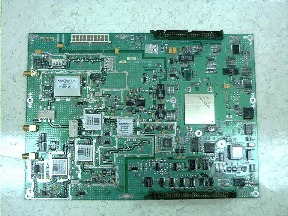
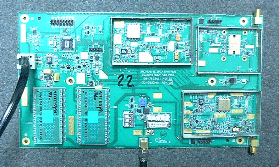
Front side Photo 1 of 2 Back side Photo 2 of 2 Front side Photo 1 of 2 Back side Photo 2 of 2 Front Side Photo 1 of 2 Back Side Photo 2 of 2
Internal Photos
Front side of PCB 1 of 2 Back side of PCB 2 of 2 Internal Photo of External Antenna
RF Exposure Info
CarrierWave Digital Radio MK-MAN-01 1 Safety Precautions PLEASE READ THESE SAFETY PRECAUTIONS! RF Energy Health Hazard The radio equipment described in this guide uses radio frequency transmitters. Although the power level is low, the concentrated energy from a directional antenna may pose a health hazard. Do not allow people to come in close proximity to the front of the antenna while the transmitter is operating. The antenna will be professional installed on fixed-mounted outdoor permanent structures where the antenna will be 2 meters away from any other antenna and all persons. Protection from Lightning Article 810 of the US National Electric Department of Energy Handbook 1996 specifies that radio and television lead-in cables must have adequate surge protection at or near the point of entry to the building. The code specifies that any shielded cable from an external antenna must have the shield directly connected to a 10 AWG wire that connects to the building ground electrode. FCC Notice, USA CarrierWave Digital Radios comply with Part 15 of the FCC rules. The radios are specifically designed to be used under Part 15, Section 15.247 of the FCC rules and regulations. Operation is subject to following conditions: • The device to utilize a fixed mount antenna, for use on a permanent outdoor structure. • The device to be installed by qualified installation/deployment personnel, and a minimum of 1 meter of separation must exist between the device and persons, when the device is operating. • The device installers and operators should be aware of the transmitter operating conditions, specified in the installation manual and other associated user documentation, as well as the antenna co-location requirements of Part 1.1307 (b) (3), of FCC rules, pertaining to RF exposure. • The device may not cause harmful interference. • The device must accept interference received, including interference that may cause undesired operation.
Test Report
File: R50214 February 18, 2003 American TCB 6731 Whittier Avenue Suite C110 McLean VA 22101 Gentlemen: The enclosed documents constitute a formal submittal and application for a Grant of Equipment Authorization pursuant to Subpart C of Part 15 of FCC Rules (CFR 47) regarding intentional radiators. Data within this report demonstrates that the equipment tested complies with the FCC limits for intentional radiators. Elliott Laboratories, as duly authorized agent prepared this submittal. A copy of the letter of our appointment as agent is enclosed. If there are any questions or if further information is needed, please contact Elliott Laboratories for assistance. Sincerely, Mark Briggs Director of Engineering MB/dmg Enclosures: Application Fee FCC Form 731 Agent Authorization Letter Emissions Test Report with Exhibits File: R50214 February 18, 2003 Certification and Engineering Bureau Industry Canada Spectrum Engineering Branch 3701 Carling Avenue, Building 94 Ottawa, Canada K2H 8S2 Gentlemen: The enclosed documents constitute a formal submittal and application for Certification pursuant to RSS-210 and RSP-100 regarding low power, license-exempt radio communications devices. Data within this report demonstrates that the equipment tested complies with the RSS-210, Issue 5 (November 2001) limits for such devices. Elliott Laboratories, as duly authorized agent prepared this submittal. A copy of the letter of our appointment as agent is enclosed. Please also find enclosed a check in the amount of US $318 to cover the assessment fee (CDN$ 470.00) and certification fee (CDN$45.00). An additional 2% surcharge was added to the exchange rate of CDN$1.00= US$318 to cover banking charges. If there are any questions or if further information is needed, please contact Elliott Laboratories for assistance. Sincerely, Mark Briggs Director of Engineering MB/dmg Enclosures: Application Form Application Fee Agent Authorization Letter Emissions Test Report with Appendices File: R50214 Page 1 of 16 Electromagnetic Emissions Test Report and Application for Grant of Equipment Authorization pursuant to FCC Part 15, Subpart C and RSS – 210 Specifications for an Intentional Radiator on the Microwave Data Systems Model: Carrier Wave 500 FCC ID: E5MDS-CW500 GRANTEE: Microwave Data Systems 175 Science Parkway Rochester, NY 14620 TEST SITE: Elliott Laboratories, Inc. 684 W. Maude Avenue Sunnyvale, CA 94086 REPORT DATE: February 18, 2003 FINAL TEST DATE: Febraury 10 and February 11, 2003 AUTHORIZED SIGNATORY: ______________________________ Mark Briggs Director of Engineering Elliott Laboratories, Inc. is accredited by the A2LA, certificate number 2016-01, to perform the test(s) listed in this report. This report shall not be reproduced, except in its entirety, without the written approval of Elliott Laboratories, Inc. Elliott Laboratories, Inc. -- EMC Department Test Report Report Date: February 18, 2003 File: R50214 Page 2 of 16 pages Equipment Name and Model: Transceiver, Carrier Wave 500 Manufacturer: Microwave Data Systems Tested to applicable standard: RSS210, Issue 5, February 1996 Low Power License-Exempt Radio Communication Devices Test Report Prepared For: Dennis McCarthy Microwave Data Systems 175 Science Parkway Rochester, NY 14620 USA Measurement Facility Description Filed With Department of Industry: Departmental Acknowledgement Number: IC2845 SV3, Dated July 3, 1997 Declaration of Compliance I declare that the testing was performed or supervised by me; that the test measurements were made in accordance with the above mentioned departmental standards (through the use of ANSI C63.4 as detailed in section 5.3 of RSS-210, Issue 5); and that the equipment performed in accordance with the data submitted in this report. Signature ______________________________ Name Mark Briggs Title Director of Engineering Elliott Laboratories Inc. Address 684 W. Maude Ave Sunnyvale, CA 94086 USA Date: February 18, 2003 Elliott Laboratories, Inc. -- EMC Department Test Report Report Date: February 18, 2003 File: R50214 Page 3 of 16 pages TABLE OF CONTENTS TABLE OF CONTENTS ..........................................................................................................................................3 SCOPE........................................................................................................................................................................4 OBJECTIVE ..............................................................................................................................................................4 STATEMENT OF COMPLIANCE.........................................................................................................................4 SUMMARY OF RESULTS ......................................................................................................................................5 OPERATION IN THE 5725 – 5850 MHZ BAND .................................................................................................5 MEASUREMENT UNCERTAINTIES..................................................................................................................6 EQUIPMENT UNDER TEST (EUT) DETAILS ....................................................................................................7 GENERAL..............................................................................................................................................................7 ENCLOSURE.........................................................................................................................................................7 MODIFICATIONS.................................................................................................................................................7 SUPPORT EQUIPMENT.......................................................................................................................................7 EXTERNAL I/O CABLING ............................…
Text truncated - open the document above for the full version.
Contact Information
Applicant
John Barenys(Senior Operations Manager)
Technical Contact
Elliott Laboratories Inc.Juan Martinez
[email protected]408-245-7800
684 West Maude Ave · Sunnyvale, California · United States
Test Firm
Elliott Laboratories LLCDavid Bare
Technical Specifications
| # | Rule Parts | Frequency Range | Power Output |
|---|---|---|---|
| 1 | 15C | 5.73 GHz - 5.84 GHz | 324.00 mW |
Other Applications from GE MDS, LLC

E5MDS-NET9S
Jul 13, 2023Frequency Hopping Radio
Equipment Class
DSS - Part 15 Spread Spectrum Transmitter
E5MDS-NET9L
Jul 11, 2023Frequency Hopping Radio
Equipment Class
DSS - Part 15 Spread Spectrum Transmitter
E5MDS-LN900
Jan 27, 2016Industrial Radio Module
Equipment Class
TNB - Licensed Non-Broadcast Station Transmitter
E5MDS-SDM4
Aug 20, 2015MDS SDM4 Licensed Spectrum Module
Equipment Class
TNB - Licensed Non-Broadcast Station Transmitter
E5MDS-LN400
Jul 09, 2015Industrial Radio Module
Equipment Class
TNB - Licensed Non-Broadcast Station Transmitter