E5MDS-EL806EL806 OEM Transnet
GE MDS, LLC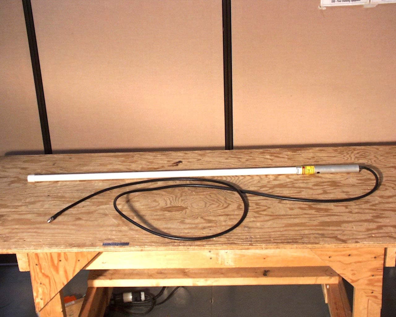
Click to zoom
Application Details
- Equipment Class
- DSS - Part 15 Spread Spectrum Transmitter
- Date of Grant
- May 13, 2003
- Application Purpose
- Original Equipment
- Date of Application
- May 13, 2003
- Equipment Note
- EL806 OEM Transnet
- Frequency Range
- 902.20000000 - 927.60000000
- Company
- GE MDS, LLC
- Country
- United States
Documents & Files
Document Text
Text extracted from the exhibit documents filed with the FCC. Open a document above to read the original.
Users Manual
Installation & Operation Guide OEM Integration Guide MDS 05-3946A01, Rev. A APRIL 2003 Microwave Data Systems Inc. MDS TransNET OEM ™ Spread Spectrum Data Transceiver Transceiver Model EL806 Including Instructions for 03-4053A01 Evaluation Development Kit The steps below contain the essential information needed to place the OEM trans- ceiver in service. Because the transceiver is designed for use in other pieces of equipment, these steps assume that prior testing and evaluation have been conducted with the host device. If not, please refer to Section 3.0, Benchtop Setup and Evaluation for proper interface wiring and configuration. 1. Mount the transceiver module using the four holes provided. • If possible, select a mounting location that allows viewing the status LEDs and provides ready access to the antenna connector. • Use standoff hardware to secure the board to the host device. • When mounting the board, use care to align the transceiver’s 16-pin header connector with the mating pins in the host device. 2. Connect the antenna system to the transceiver • Use only with antenna/feedline assemblies that have been expressly tested and approved for such service by Microwave Data Systems Inc. • Use an MMCX-type male connector to attach the antenna to the transceiver. • For best performance, antennas should be mounted in the clear, with an unobstructed path in the direction of desired transmission/reception. 3. Apply power and observe the LEDs for proper operation. The LED command must be set to ON (LEDS ON). After 16 seconds... • The GP lamp should be lit continuously • The DCD lamp should be lit continuously—if synchronization with another unit has been achieved • The Remote radio(s) should be transmitting data (TXD) and receiving data (RXD) with its associated station LED Indicator Descriptions LED NameDescription RXD (CR3) Receive Data Serial receive data activity. Payload data from con- nected device. TXD (CR4) Transmit Data Serial transmit data activity. Payload data to con- nected device. DCD (CR5) Data Carrier Detect Continuous—Radio is receiving/sending synchro- nization frames On within 10 seconds of power-up under normal conditions GP (CR6) General Purpose • Continuous—Power is applied to the radio; no problems detected • Flashing (5 times-per-second)—Fault indication. See “TROUBLESHOOTING” on Page 52 • Off—Radio is unpowered or in Sleep mode QUICK START GUIDE RXD TXD DCD GP MDS 05-3946A01, Rev. ATransNET OEM Integration Guidei CONTENTS 1.0 ABOUT THIS MANUAL..........................................................1 2.0 PRODUCT DESCRIPTION....................................................1 2.1 Transceiver Features .......................................................2 2.2 Model Configuration Codes ............................................2 2.3 Spread Spectrum Transmission ......................................3 2.4 Typical Applications .........................................................3 Multiple Address Systems (MAS) ....................................3 Point-to-Point System ......................................................4 Tail-End Link to an Existing Network ...............................5 Store-and-Forward Repeater ...........................................5 2.5 Transceiver Accessories .................................................6 3.0 BENCHTOP SETUP & EVALUATION ....................................7 3.1 Evaluation Development Kit (P/N 03-4053A01) ..............7 Evaluation Board .............................................................8 Connecting the Eval. Board & Transceiver (Figure 8) ......9 3.2 Cable Connections for Benchtop Testing ........................10 Antenna Connection (J200 on the transceiver module)...10 Diagnostic Connection (J4)..............................................11 Data Connector (J5) ........................................................12 DC Power Connector (J3) ................................................14 Jumper Block J1 (DC Power Configuration) ....................15 3.3 Initial Power-Up & Configuration .....................................15 Configuration Settings .....................................................16 LED Indicators .................................................................17 4.0 EVALUATION BOARD DOCUMENTATION ...........................18 4.1 Assembly Drawing ..........................................................18 4.2 Parts List .........................................................................18 4.3 Evaluation Board Fuse Replacement .............................20 5.0 TRANSCEIVER MOUNTING .................................................21 iiTransNET OEM Integration GuideMDS 05-3946A01, Rev. A 5.1 Mounting Dimensions ..................................................... 21 5.2 Antennas & Feedlines .................................................... 21 Feedlines......................................................................... 22 6.0 OPTIMIZING PERFORMANCE............................................. 23 6.1 Antenna Aiming .............................................................. 23 6.2 Antenna SWR Check ..................................................... 23 6.3 Data Buffer Setting ......................................................... 23 6.4 Hoptime Setting .............................................................. 23 6.5 Operation at 115200 bps ................................................ 24 6.6 Baud Rate Setting .......................................................... 24 6.7 Radio Interference Checks ............................................. 24 6.8 RF Output Setting ........................................................... 24 7.0 OPERATING PRINCIPLES & SPECIAL CONFIGURATIONS ...................................................................... 25 7.1 How Remotes Acquire Synchronization ......................... 25 7.2 Establishing a Tail-End Link ............................................ 25 7.3 Store & Forward (SAF) Operation w…
Text truncated - open the document above for the full version.
Cover Letter(s)
175 Science Parkway, Rochester, New York 14620 USA (585) 242-9600 Phone (585) 242-9620 Fax November 13, 2002 FEDERAL COMMUNICATIONS COMMISSION 7435 Oakland Mills Road Columbia, MD 21046 U.S.A. Subject: Request for withholding from public disclosure the schematic diagrams and system block diagrams pursuant to an application for certification. Applicant: Microwave Data Systems Inc. Product: EL806 OEM Transnet Model: EL806 FCC ID: E5MDS-EL806 Dear Sir/Madam, We, Microwave Data Systems, would like to request that the schematic diagrams, system block diagram, Theory of Operation and Bill of Materials submitted with the application for certification be withheld from public disclosure as per Section 0.459 of FCC Rules. This request is made under the provisions of Section 0.457(d) of the Commission's Rules, and Section 552(b)(4) of the Freedom of Information Act. These sections authorize as a withholding from public inspection materials which would be privileged as a matter of law if retained by the person submitting them, and materials which would not customarily be released to the public by that person. If you have any queries, please do not hesitate to contact me at 585 242-8440: Yours truly, Dennis McCarthy Agency Compliance Engineer Microwave Data Systems 175 Science Parkway Rochester NY 14620 Phone (585) 242-8440 Email [email protected]
Cover Letter(s)
May 5, 2003 Timco Engineering, Inc. 849 N.W. State Road 45 P.O. Box 370 Newberry, Florida 32669 USA Subject: FCC Certification Authorization Application Under FCC PART 15, Subpart C, Section 15.247 - Frequency Hopping Spread Spectrum Transmitters Operating in the Frequency Band 902.2 - 927.6 MHz. Product: EL806 OEM Transnet Model No.: EL806 FCC ID: E5MDS-EL806 Dear Sir/Madam As appointed agent for Microwave Data Systems Inc., we would like to submit the application to the Federal Communications Commission for certification of the above product. Please review all necessary files uploaded to TIMCO electronic filing site for detailed information. This application is for Modular Approval of the above product pertaining to Mobile and Fixed and Base Stations with the antennas specified in this submission (See section 6.5 of the Engineering Test Report, which addresses the modular approval requirements of FCC DA 00-1407). Separate approval is required for operations with respect to § 2.1093 as a portable transmitter. Grant Note: Output is peak conducted RF power at antenna terminals. The antenna(s) used for this transmitter module must be installed to provide a separation distance of at least 23 cm from all persons and must not be co-located or operating in conjunction with any other antenna or transmitter. End-users and installers must be provided with antenna installation and transmitter operating conditions for satisfying RF exposure compliance. This module is approved for use with the following MDS ClearWave Antennas: Z1523A/B/C (8.5 dBi) yagi directional Z1526 (7.1 dBi) omni directional base station Z1527 (0 dBi) ½ wave dipole The output power is required to be adjusted for different antennas as specified in OEM integration guide and test report. If you have any queries, please do not hesitate to contact us. Yours truly, Tri Minh Luu, P. Eng., V.P., Engineering UltraTech Group of La bs 31040/SIT A96/TH/0093 46390-2049 200093-0 2 00-034 3000 Bristol Circle, Oakville, Ontario, Canada L6H 6G4 Telephone (905) 829-1570 Facsimile (905) 829-8050 Website: www.ultratech-labs.com Email: [email protected]
External Photos
ANNEX 2 – EXTERNAL EUT PHOTOS Microwave Data Systems Inc. EL806 OEM Transnet, Model EL806 FCC ID: E5MDS-EL806 IC: 3738A-MDSEL806 A2 - 1 ANNEX 2 – EXTERNAL EUT PHOTOS Microwave Data Systems Inc. EL806 OEM Transnet, Model EL806 FCC ID: E5MDS-EL806 IC: 3738A-MDSEL806 A2 - 2 ANNEX 2 – EXTERNAL EUT PHOTOS Microwave Data Systems Inc. EL806 OEM Transnet, Model EL806 FCC ID: E5MDS-EL806 IC: 3738A-MDSEL806 A2 - 3 ANNEX 2 – EXTERNAL EUT PHOTOS Microwave Data Systems Inc. EL806 OEM Transnet, Model EL806 FCC ID: E5MDS-EL806 IC: 3738A-MDSEL806 A2 - 4 ANNEX 2 – EXTERNAL EUT PHOTOS Microwave Data Systems Inc. EL806 OEM Transnet, Model EL806 FCC ID: E5MDS-EL806 IC: 3738A-MDSEL806 A2 - 5 ANNEX 2 – EXTERNAL EUT PHOTOS Microwave Data Systems Inc. EL806 OEM Transnet, Model EL806 FCC ID: E5MDS-EL806 IC: 3738A-MDSEL806 A2 - 6 MDS ClearWave Antennas 902-928 MHz unity (0 dBi) ½ wave dipole w/swivel RPTNC connector Model: Z1527 ANNEX 2 – EXTERNAL EUT PHOTOS Microwave Data Systems Inc. EL806 OEM Transnet, Model EL806 FCC ID: E5MDS-EL806 IC: 3738A-MDSEL806 A2 - 7 MDS ClearWave Antennas 902-928 MHz 5 dBd (7.1 dBi) omni directional base station antenna with integral RG213 10ft pigtail and RPTNC (plug) male connector. Includes MMK9 heavy duty bracket for use with pipe OD’s of up to 2 ½”. Model: Z1526 ANNEX 2 – EXTERNAL EUT PHOTOS Microwave Data Systems Inc. EL806 OEM Transnet, Model EL806 FCC ID: E5MDS-EL806 IC: 3738A-MDSEL806 A2 - 8 MDS ClearWave Antennas 902-960 MHz 6.4 dBd (8.5 dBi) yagi directional antenna, Black Teflon impregnated CORVEL® powder coat w/ 10ft. LMR 400 cable heat shrunk to boom and RPTNC (plug) male connector on the end includes MYK14 Heavy duty mounting bracket. Model: Z1523A ANNEX 2 – EXTERNAL EUT PHOTOS Microwave Data Systems Inc. EL806 OEM Transnet, Model EL806 FCC ID: E5MDS-EL806 IC: 3738A-MDSEL806 A2 - 9 MDS ClearWave Antennas 18” LMR100A cable assembly with RAMMCX connector and RPTNC (jack) female connector Model: Z1528
ID Label/Location Info
MDS 05-3946A01, Rev. ATransNET OEM Integration Guidev The transceiver has been recognized for use in these hazardous locations by two independent agencies —Underwriters Laboratories (UL) and the Canadian Standards Association (CSA). The UL certification for the transceiver is as a Recognized Component for use in these hazardous locations, in accordance with UL Standard 1604. The CSA Certification is in accordance with CSA STD C22.2 No. 213-M1987. UL/CSA Conditions of Approval: The transceiver is not acceptable as a stand-alone unit for use in the hazardous locations described above. It must either be mounted within another piece of equipment which is certified for hazardous locations, or installed within guidelines, or conditions of approval, as set forth by the approving agencies. These conditions of approval are as follows: 1. The transceiver must be mounted within a separate enclosure which is suitable for the intended application. 2. The antenna feedline, DC power cable and interface cable must be routed through conduit in accordance with the National Electrical Code. 3. Installation, operation and maintenance of the transceiver should be in accordance with the transceiver's installation manual, and the National Electrical Code. 4. Tampering or replacement with non-factory components may adversely affect the safe use of the transceiver in hazardous locations, and may void the approval. 5. A power connector with screw-type retaining screws as supplied by MDS must be used. When installed in a Class I, Div. 2, Groups A, B, C or D hazardous location, observe the fol- lowing: WARNING EXPLOSION HAZARD Do not disconnect equipment unless power has been switched off or the area is know to be non-hazardous. Refer to Articles 500 through 502 of the National Electrical Code (NFPA 70) for further infor- mation on hazardous locations and approved Division 2 wiring methods. FCC Part 15 Notice The transceiver described herein complies with Part 15 of the FCC Rules. Operation is subject to the following two conditions: (1) this device may not cause harmful interference, and (2) this device must accept any interference received, including interference that may cause undesired operation. This device is specifically designed to be used under Section 15.247 of the FCC Rules and Regulations. Any unauthorized modification or changes to this device without the express approval of Microwave Data Systems may void the user’s authority to operate this device. Fur- thermore, this device is intended to be used only when installed in accordance with the instruc- tions outlined in this manual. Failure to comply with these instructions may also void the user’s authority to operate this device. Limited Modular Approval (LMA) Notice: This device is offered as an FCC Part 15 Unlicensed Modular Transmitter. This Modular Trans- mitter is approved for use only with specific antenna, cable and output power configurations that have been tested and approved by the manufacturer (Microwave Data Systems Inc.). Modifica- tions to the radio, the antenna system, or power output, that have not been explicitly specified by the manufacturer are not permitted, and may render the radio non-compliant with applicable reg- ulatory authorities. This device employs a unique connector at all connections between the module and the antenna, including the cable. Consult MDS for approved antenna/cable assemblies in our product offering. When this device is placed inside an enclosure, a durable label must be affixed to the outside of that enclosure which includes this module’s FCC ID Number Manual Revision and Accuracy While every reasonable effort has been made to ensure the accuracy of this manual, product improvements may result in minor differences between the manual and the product shipped to you. If you have additional questions or need an exact specification for a product, please contact our Customer Service Team using the information at the back of this guide. In addition, manual updates can often be found on the MDS Web site at www.microwavedata.com.
Internal Photos
ANNEX 3 – INTERNAL EUT PHOTOS Microwave Data Systems Inc. EL806 OEM Transnet, Model EL806 FCC ID: E5MDS-EL806 IC: 3738A-MDSEL806 A3 - 1 ANNEX 3 – INTERNAL EUT PHOTOS Microwave Data Systems Inc. EL806 OEM Transnet, Model EL806 FCC ID: E5MDS-EL806 IC: 3738A-MDSEL806 A3 - 2 ANNEX 3 – INTERNAL EUT PHOTOS Microwave Data Systems Inc. EL806 OEM Transnet, Model EL806 FCC ID: E5MDS-EL806 IC: 3738A-MDSEL806 A3 - 3
Test Report
EL806 OEM Transnet Model No.: EL806 FCC ID: E5MDS-EL806 Applicant: Microwave Data Systems Inc. 175 Science Parkway Rochester, NY USA, 14620 In Accordance With Federal Communications Commission (FCC) Part 15, Subpart C, Section 15.247 Frequency Hopping Spread Spectrum Transmitters Operating in the Frequency Band 902.2 - 927.6 MHz UltraTech's File No.: MIC-068F247 This Test report is Issued under the Authority of Tri M. Luu, Professional Engineer, Vice President of Engineering UltraTech Group of Labs Date: May 5, 2003 Report Prepared by: Dan Huynh Issued Date: May 5, 2003 Tested by: Mr. Hung Trinh, EMI/RFI Technician Test Dates: Feb. 3 – Apr. 25 & May 5, 2003 The results in this Test Report apply only to the sample(s) tested, and the sample tested is randomly selected. This report must not be used by the client to claim product endorsement by NVLAP or any agency of the US Government. UltraTech 3000 Bristol Circle, Oakville, Ontario, Canada, L6H 6G4 Tel.: (905) 829-1570 Fax.: (905) 829-8050 Website: www.ultratech-labs.com , Email: [email protected], Email: [email protected] 2 31040/SIT C-1376 46390-2049 200093-0 00-034 FCC Part 15, Subpart C, Section 15.247 - Frequency Hopping Spread Spectrum Transmitters Contents i EL806 OEM Transnet, Model EL806 FCC ID: E5MDS-EL806 ULTRATECH GROUP OF LABS File #: MIC-068F247 3000 Bristol Circle, Oakville, Ontario, Canada L6H 6G4 May 5, 2003 Tel. #: 905-829-1570, Fax. #: 905-829-8050, Email: [email protected] , Website: http://www.ultratech-labs.com All test results contained in this engineering test report are traceable to National Institute of Standards and Technology (NIST) TABLE OF CONTENTS EXHIBIT 1. SUBMITTAL CHECK LIST ..................................................................................................................................... 1 EXHIBIT 2. INTRODUCTION....................................................................................................................................................... 2 2.1. SCOPE ....................................................................................................................................................................................... 2 2.2. RELATED SUBMITTAL(S)/GRANT(S)............................................................................................................................................... 2 2.3. NORMATIVE REFERENCES .................................................................................................................................................. 2 EXHIBIT 3. PERFORMANCE ASSESSMENT ............................................................................................................................ 3 3.1. CLIENT INFORMATION ............................................................................................................................................................ 3 3.2. E QUIPMENT UNDER TEST (EUT) INFORMATION...................................................................................................................... 3 3.3. EUT’S TECHNICAL SPECIFICATIONS................................................................................................................................. 4 3.4. A SSOCIATED ANTENNAS AND CABLE ASSEMBLY........................................................................................................................... 4 3.5. L IST OF EUT’S PORTS................................................................................................................................................................. 5 3.6. A NCILLARY EQUIPMENT............................................................................................................................................................... 5 EXHIBIT 4. EUT OPERATING CONDITIONS AND CONFIGURATIONS DURING TESTS ............................................. 6 4.1. C LIMATE TEST CONDITIONS.......................................................................................................................................................... 6 4.2. O PERATIONAL TEST CONDITIONS & ARRANGEMENT FOR TESTS .................................................................................................... 6 EXHIBIT 5. SUMMARY OF TEST RESULTS............................................................................................................................. 7 5.1. LOCATION OF TESTS............................................................................................................................................................. 7 5.2. APPLICABILITY & S UMMARY OF EMC EMISSION TEST RESULTS........................................................................................... 7 5.3. MODIFICATIONS INCORPORATED IN THE EUT FOR COMPLIANCE PURPOSES...................................................................................... 7 EXHIBIT 6. MEASUREMENTS, EXAMINATIONS & TEST DATA FOR EMC EMISSIONS ............................................. 8 6.1. TEST PROCEDURES...................................................................................................................................................................... 8 6.2. MEASUREMENT UNCERTAINTIES................................................................................................................................................... 8 6.3. MEASUREMENT EQUIPMENT USED................................................................................................................................................. 8 6.4. ESSENTIAL/PRIMARY FUNCTIONS AS DECLARED BY THE MANUACTURER ......................................................... 8 6.5. UNLICENSED MODULAR TRANSMITTER APPROVAL REQUIREMENTS @ FCC PUBLIC NOTICE DA 00-1407 (JUNE 26, 2000) ........... 9 6.6. COMPLI ANCE WITH FCC PART 15 – GENERAL TECHNICAL REQUIREMENTS ....................................................... 12 6.7. AC POWERLINE CONDUCTED E MISSIONS [47 CFR §15.107(B)]...…
Text truncated - open the document above for the full version.
Test Report
EL806 OEM TransNet Model No.: EL806 Applicant: Microwave Data Systems Inc. 175 Science Parkway Rochester, NY USA, 14620 Tested in Accordance With Federal Communications Commission (FCC) 47 CFR, Part 15, Subpart B Class A Unintentional Radiators & Radio Receivers Operating in the Frequency Band 902 - 928 MHz UltraTech's File No.: MIC-068FRX This Test report is Issued under the Authority of Tri M. Luu, Professional Engineer, Vice President of Engineering UltraTech Group of Labs Date: March 24, 2003 Report Prepared by: Dan Huynh Issued Date: March 24, 2003 Tested by: Hung Trinh, RFI/EMI Technician Test Dates: Feb. 21 & Mar. 4, 2003 The results in this Test Report apply only to the sample(s) tested, and the sample tested is randomly selected. This report must not be used by the client to claim product endorsement by NVLAP or any agency of the US Government. UltraTech 3000 Bristol Circle, Oakville, Ontario, Canada, L6H 6G4 Tel.: (905) 829-1570 Fax.: (905) 829-8050 Website: www.ultratech-labs.com , Email: [email protected], Email: [email protected] 2 31040/SIT C-1376 46390-2049 200093-0 00-034 FCC Part 15, Subpart B, Class A Unintentional Radiators and Radio Receivers Contents i EL806 OEM Transnet Model EL806 ULTRATECH GROUP OF LABS File #: MIC-068FRX 3000 Bristol Circle, Oakville, Ontario, Canada L6H 6G4 March 24, 2003 Tel. #: 905-829-1570, Fax. #: 905-829-8050, Email: [email protected] , Website: http://www.ultratech-labs.com All test results contained in this engineering test report are traceable to National Institute of Standards and Technology (NIST) TABLE OF CONTENTS EXHIBIT 1. INTRODUCTION ....................................................................................................................................... 3 1.1. SCOPE......................................................................................................................................................................... 3 1.2. RELATED SUBMITTAL(S)/GRANT(S)............................................................................................................................. 3 1.3. NORMATIVE REFERENCES........................................................................................................................................... 3 EXHIBIT 2. PERFORMANCE ASSESSMENT ............................................................................................................ 4 2.1. CLIENT INFORMATION................................................................................................................................................. 4 2.2. EQUIPMENT UNDER TEST (EUT) INFORMATION............................................................................................................ 4 2.3. EUT’S TECHNICAL SPECIFICATIONS............................................................................................................................. 5 2.4. LIST OF EUT’S PORTS................................................................................................................................................... 5 2.5. ANCILLARY EQUIPMENT............................................................................................................................................. 5 EXHIBIT 3. EUT OPERATING CONDITIONS AND CONFIGURATIONS DURING TESTS ............................. 6 3.1. CLIMATE TEST CONDITIONS........................................................................................................................................ 6 3.2. OPERATIONAL TEST CONDITIONS & ARRANGEMENT FOR TEST SIGNALS...................................................................... 6 EXHIBIT 4. SUMMARY OF TEST RESULTS ............................................................................................................. 7 4.1. LOCATION OF TESTS.................................................................................................................................................... 7 4.2. APPLICABILITY & SUMMARY OF EMC EMISSION TEST RESULTS................................................................................... 7 4.3. MODIFICATIONS REQUIRED FOR COMPLIANCE............................................................................................................. 7 EXHIBIT 5. MEASUREMENTS, EXAMINATIONS & TEST DATA FOR EMC EMISSIONS............................. 8 5.1. TEST PROCEDURES...................................................................................................................................................... 8 5.2. MEASUREMENT UNCERTAINTIES................................................................................................................................. 8 5.3. MEASUREMENT EQUIPMENT USED...............................................................................................................................8 5.4. ESSENTIAL/PRIMARY FUNCTIONS AS DECLARED BY THE MANUFACTURER.................................................................. 8 5.5. AC POWERLINE CONDUCTED EMISSIONS [47 CFR §15.107(B)]......................................................................... 9 5.6. RECEIVER SPURIOUS/HARMONIC RADIATED EMISSIONS [47 CFR §15.109(B)]............................................................ 12 5.7. RADIATED EMISSIONS FROM CLASS A UNINTENTIONAL RADIATORS (DIGITAL DEVICES) [47 CFR §15.109(B)]........... 15 5.8. RECEIVER ANTENNA POWER SPURIOUS/HARMONIC CONDUCTED EMISSIONS [47 CFR §15.111(A)] ............................ 17 EXHIBIT 6. MEASUREMENT UNCERTAINTY....................................................................................................... 21 6.1. LINE CONDUCTED EMISSION MEASUREMENT UNCERTAINTY...................................................................................... 21 6.2. RADIATED EMISSION MEASUREMENT UNCERTAINTY................................................................................................. 22 EXHIBIT 7. MEASUREMENT METHODS .................................…
Text truncated - open the document above for the full version.
Test Setup Photos
ANNEX 1 - TEST SETUP PHOTOS Microwave Data Systems Inc. EL806 OEM Transnet, Model EL806 FCC ID: E5MDS-EL806 IC: 3738A-MDSEL806 A1 - 1 EUT with MDS ClearWave ½ Wave Dipole Antenna ANNEX 1 - TEST SETUP PHOTOS Microwave Data Systems Inc. EL806 OEM Transnet, Model EL806 FCC ID: E5MDS-EL806 IC: 3738A-MDSEL806 A1 - 2 EUT with MDS ClearWave ½ Wave Dipole Antenna ANNEX 1 - TEST SETUP PHOTOS Microwave Data Systems Inc. EL806 OEM Transnet, Model EL806 FCC ID: E5MDS-EL806 IC: 3738A-MDSEL806 A1 - 3 EUT with MDS ClearWave ½ Wave Dipole Antenna ANNEX 1 - TEST SETUP PHOTOS Microwave Data Systems Inc. EL806 OEM Transnet, Model EL806 FCC ID: E5MDS-EL806 IC: 3738A-MDSEL806 A1 - 4 EUT with MDS ClearWave ½ Wave Dipole Antenna ANNEX 1 - TEST SETUP PHOTOS Microwave Data Systems Inc. EL806 OEM Transnet, Model EL806 FCC ID: E5MDS-EL806 IC: 3738A-MDSEL806 A1 - 5 EUT with MDS ClearWave ½ Wave Dipole Antenna ANNEX 1 - TEST SETUP PHOTOS Microwave Data Systems Inc. EL806 OEM Transnet, Model EL806 FCC ID: E5MDS-EL806 IC: 3738A-MDSEL806 A1 - 6 EUT with MDS ClearWave ½ Wave Dipole Antenna ANNEX 1 - TEST SETUP PHOTOS Microwave Data Systems Inc. EL806 OEM Transnet, Model EL806 FCC ID: E5MDS-EL806 IC: 3738A-MDSEL806 A1 - 7 EUT with MDS ClearWave Omni-directional Base Station Antenna ANNEX 1 - TEST SETUP PHOTOS Microwave Data Systems Inc. EL806 OEM Transnet, Model EL806 FCC ID: E5MDS-EL806 IC: 3738A-MDSEL806 A1 - 8 EUT with MDS ClearWave Omni-directional Base Station Antenna ANNEX 1 - TEST SETUP PHOTOS Microwave Data Systems Inc. EL806 OEM Transnet, Model EL806 FCC ID: E5MDS-EL806 IC: 3738A-MDSEL806 A1 - 9 EUT with MDS ClearWave Omni-directional Base Station Antenna ANNEX 1 - TEST SETUP PHOTOS Microwave Data Systems Inc. EL806 OEM Transnet, Model EL806 FCC ID: E5MDS-EL806 IC: 3738A-MDSEL806 A1 - 10 EUT with MDS ClearWave Yagi Directional Antenna ANNEX 1 - TEST SETUP PHOTOS Microwave Data Systems Inc. EL806 OEM Transnet, Model EL806 FCC ID: E5MDS-EL806 IC: 3738A-MDSEL806 A1 - 11 EUT with MDS ClearWave Yagi Directional Antenna ANNEX 1 - TEST SETUP PHOTOS Microwave Data …
Text truncated - open the document above for the full version.
Contact Information
Applicant
John Barenys(Senior Operations Manager)
Test Firm
UltraTech Engineering Labs Inc.Tri Luu
Technical Specifications
| # | Rule Parts | Frequency Range | Power Output |
|---|---|---|---|
| 1 | 15C | 902.2 MHz - 927.6 MHz | 1 W |
Other Applications from GE MDS, LLC

E5MDS-NET9S
Jul 13, 2023Frequency Hopping Radio
Equipment Class
DSS - Part 15 Spread Spectrum Transmitter
E5MDS-NET9L
Jul 11, 2023Frequency Hopping Radio
Equipment Class
DSS - Part 15 Spread Spectrum Transmitter
E5MDS-LN900
Jan 27, 2016Industrial Radio Module
Equipment Class
TNB - Licensed Non-Broadcast Station Transmitter
E5MDS-SDM4
Aug 20, 2015MDS SDM4 Licensed Spectrum Module
Equipment Class
TNB - Licensed Non-Broadcast Station Transmitter
E5MDS-LN400
Jul 09, 2015Industrial Radio Module
Equipment Class
TNB - Licensed Non-Broadcast Station Transmitter