E5MDS-ENETL2WMDS eNETL2W 20-Watt RF Amplifier
GE MDS, LLC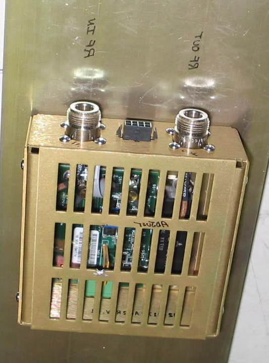
Click to zoom
Application Details
- Equipment Class
- AMP - Amplifier
- Date of Grant
- Jun 02, 2004
- Application Purpose
- Original Equipment
- Date of Application
- Jun 02, 2004
- Equipment Note
- MDS eNETL2W 20-Watt RF Amplifier
- Frequency Range
- 217.00000000 - 222.00000000
- Company
- GE MDS, LLC
- Country
- United States
Documents & Files
Document Text
Text extracted from the exhibit documents filed with the FCC. Open a document above to read the original.
Users Manual
MDS 05-4218A01, Rev. 01eNETL2W 20-Watt Power Amplifier Page 1 of 1 INTRODUCTION The eNETL2W (Figure 1) is a 20-watt RF power amplifier designed for use in the 217–222 MHz frequency range. It is intended to serve as a 100% duty cycle amplifier for MDS entraNET 220 radio modules (ROR220) operating in point-to- multipoint repeater applications. The amplifier is designed to comply with FCC Part 90 and FCC Part 15 requirements. Figure 1. MDS eNETL2W RF Power Amplifier (Top cover removed to show internal layout) Product Description The eNETL2W power amplifier consists of a RF amplifier and PCB mounted to a heat sink, with a DC Power interface, power control interface, and input/output RF connections on the sidewalls of the chassis. DC power is supplied to the amplifier from a regulated and filtered DC source capable of supplying 10-16 Vdc at a maximum current of 5 Amperes. The DC power source should be current limited or have a protective fuse or circuit breaker. INSTALLATION Mounting the Unit The amplifier is designed for mounting in a standard 19 -inch rack cabinet using the 3U panel provided. Four screws (not pro- vided) are required to attach the panel to the rack sides. This panel also serves as a heat sink for the PA module, and is nor- mally mounted with the cooling fins facing outward. External Connections To place the amplifier module in service, make the following ca- ble connections: 1. Using low loss 50-ohm coaxial cable, connect the RF Input connector (J103) to the RF output connector of the MDS entraNET 220 radio module (ROR220). 2. Using low loss 50-ohm coaxial cable, connect the RF Output connector (J102) to the station duplexer. 3. Connect the Power Control interface (J101) to the MDS entraNET 220 radio module (ROR220) in accordance with the pin connections listed below. J101 is an 8-pin Molex polarized connector. Pin 1—3 Vdc enable TX, low=off Pin 2—0.7 Vdc (varies to set RF power) Pin 3—Not used Pin 4—Ground 4. Connect 10-16 Vdc power supply to the Power connector (J100). The left pin is positive (+); the right is negative(–). RF Power Output Check/Adjustment To check/set the amplifier’s RF power output level, proceed as follows: 1. Connect a wattmeter (rated for use at 220 MHz, and at least 20 watts) to the amplifier’s RF output connector (J102). Terminate the wattmeter into a 50-ohm, non- inductive load. 2. Apply RF drive from the MDS entraNET 220 radio module (ROR220) and note the RF power indication at J102. 3. If necessary, adjust R115 (see Figure 1) with an insulated flat blade tool to achieve the desired output level. Access to R115 is available through a top cover vent slot. UNIT SPECIFICATIONS Operating Voltage: 10-16 Vdc Maximum Current Draw: 5 Amperes RF Drive Power: 100 mW RF Out: +40 to +43 dBm (10-20 watts), adjustable Operating Frequency: 217-220 MHz Mounting: standard 19-inch rack cabinet Weight: 5.15 lbs. Dimensions: 5.25” H x 19” W x 2.88” D (13.34 H x 48.26 W x 7.31 D cm) TECHNICAL ASSISTANCE Technical assistance for MDS products is available by using one of these methods to contact us: Telephone: 585.241.5510 FAX: 585.242.8369 E-mail: [email protected] Web: www.microwavedata.com Instruction Sheet MDS eNETL2W 20-Watt RF Amplifier Microwave Data Systems Inc., 175 Science Parkway, Rochester, NY 14620 USA Tel. 585.242-9600 FAX 585.242-9620 www.microwavedata.com
Attestation Statements
175 Science Parkway, Rochester, New York 14620 USA (585) 242-9600 Phone (585) 242-9620 Fax May 20, 2004 FEDERAL COMMUNICATIONS COMMISSION 7435 Oakland Mills Road Columbia, MD 21046 USA Subject: Part 90.203(e) Compliance Attestation Applicant: Microwave Data Systems Inc. Product: ENETL2W RF 20 watt amplifier Model: ENETL2W FCC ID: E5MDS- ENETL2W Dear Sir or Madam: This equipment meets the requirements of the FCC Rules, Parts 90.203(e) except as provided in paragraph (g) of the section 203. The operator cannot program and transmit on frequencies other than those programmed by the manufacturer, service or maintenance personnel, using the equipment’s external operational controls. Yours sincerely Dennis McCarthy Agency Compliance Engineer Microwave Data Systems 175 Science Parkway Rochester NY 14620 Phone (585) 242-8440 Email [email protected]
Cover Letter(s)
175 Science Parkway, Rochester, New York 14620 USA (585) 242-9600 Phone (585) 242-9620 Fax May 20, 2004 FEDERAL COMMUNICATIONS COMMISSION 7435 Oakland Mills Road Columbia, MD 21046 U.S.A. Subject: Request for withholding from public disclosure the schematic diagrams and system block diagrams pursuant to an application for certification. Applicant: Microwave Data Systems Inc. Product: 220MHz 20 watt RF ampilfier Model: ENETL2W FCC ID: E5MDS- ENETL2W Dear Sir/Madam, We, Microwave Data Systems Inc., would like to request that the schematic diagrams, Theory of Operation and Bill of Materials submitted with the application for certification be withheld from public disclosure as per Section 0.459 of FCC Rules. This request is made under the provisions of Section 0.457(d) of the Commission's Rules, and Section 552(b)(4) of the Freedom of Information Act. These sections authorize as a withholding from public inspection materials which would be privileged as a matter of law if retained by the person submitting them, and materials which would not customarily be released to the public by that person. If you have any queries, please do not hesitate to contact me at 585 242-8440: Yours truly, Dennis McCarthy Agency Compliance Engineer Microwave Data Systems 175 Science Parkway Rochester NY 14620 Phone (585) 242-8440 Email [email protected]
Cover Letter(s)
175 Science Parkway, Rochester, New York 14620 USA (585) 242-9600 Phone (585) 242-9620 Fax May 20, 2004 FEDERAL COMMUNICATIONS COMMISSION 7435 Oakland Mills Road Columbia, MD 21046 U.S.A. Subject: Authority to Act as an Agent to FCC Applicant: Microwave Data Systems Inc. Product: ENETL2W RF Amplifier NEW FCC ID: E5MDS- ENETL2W Dear Sir/Madam, I hereby appoint Elliott Labs of Sunnyvale Calif. to act as my agent in preparation of this application to F.C.C. for authorization of equipment under F.C.C. Rules. I also certify that the information provided, properly described the device or system for which authorization is required. If you have any queries, please do not hesitate to contact me at 585 242-8440: Yours truly, Dennis McCarthy Agency Compliance Engineer Microwave Data Systems 175 Science Parkway Rochester NY 14620 Phone (585) 242-8440 Email [email protected]
Cover Letter(s)
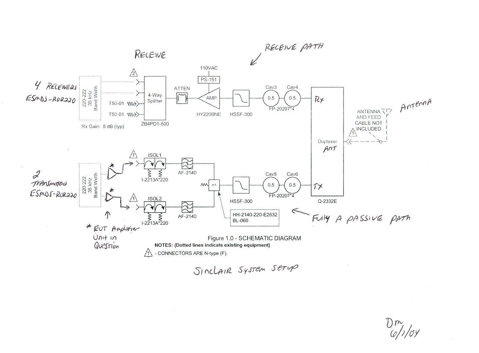
American Telecommunications Certification Body Inc. 6731 Whittier Ave, McLean, VA 22101 May 28, 2004 RE: FCC ID: E5MDS-ENETL2W_ATCB001375 Attention: Juan Martinez I have a few comments on this Application. Please note that further comments may arise in response to answers provided to the questions below. 1. Please note that a device used in line that does not directly radiate rf energy is not certified. This device is said to connect from an rf module to a duplexer. However, it is not made clear what the function of this duplexer is (i.e. does it switch the rf output of this device to multiple antennae or does it switch the rf output to other active system input ports and not to an antenna?). If the later is true, then the device would not be certified as it would not be classified as a transmitter or amplifier connecting to an antenna or other radiating source. If the former is true, then the duplexer would have to be clearly defined and identified in the documentation and in the grant notes of the device certificate. Please explain the function of the duplex operation. I f this is a certifiable device, please include a diagram of how this device connects directly to a radiated element via the duplexer. Dennis Ward mailto:[email protected] The items indicated above must be submitted before processing can continue on the above referenced application. Failure to provide the requested information may result in application termination. Correspondence should be considered part of the permanent submission and may be viewed from the Internet after a Grant of Equipment Authorization is issued. Please do not respond to this correspondence using the email reply button. In order for your response to be processed expeditiously, you must submit your documents through the AmericanTCB.com website. Also, please note that partial responses increase processing time and should not be submitted. Any questions about the content of this correspondence should be directed to the sender.
ID Label/Location Info
Label Location
Internal Photos
FRONT SIDE OF AMPLIFIER BOARD BACK SIDE OF AMPLIFIER BOARD
Test Report
File: R55756 Page 1 of 6 Electromagnetic Emissions Test Report In Accordance With Industry Canada Radio Standards Specification 119 Issue 6, FCC Part 90 on the Microwave Data Systems Transmitter Model: ROR220 PA FCC ID NUMBER: E5MDS-ENETL2W UPN: 3738A-ENETL2W GRANTEE: Microwave Data Systems 175 Science Parkway Rochester, NY 14620 TEST SITE: Elliott Laboratories, Inc. 684 W. Maude Avenue Sunnyvale, CA 94086 REPORT DATE: May 25, 2004 FINAL TEST DATE: May 14 and May 22, 2004 AUTHORIZED SIGNATORY: ______________________________ Juan Martinez Senior EMC Engineer Elliott Laboratories, Inc. is accredited by the A2LA, certificate number 2016-01, to perform the test(s) listed in this report. This report shall not be reproduced, except in its entirety, without the written approval of Elliott Laboratories, Inc. Elliott Laboratories, Inc. -- EMC Department Test Report Report Date: May 25, 2004 File: R55756 Page 2 of 7 TABLE OF CONTENTS COVER PAGE.............................................................................................................................................................1 TABLE OF CONTENTS ..........................................................................................................................................2 FCC CERTIFICATION INFORMATION.............................................................................................................3 DECLARATIONS OF COMPLIANCE..................................................................................................................5 SCOPE........................................................................................................................................................................6 OBJECTIVE ..............................................................................................................................................................6 SUMMARY OF TEST RESULTS ...........................................................................................................................7 PART 90 AND RSS-119 TEST SUMMARY.............................................................................................................7 MEASUREMENT UNCERTAINTIES ...................................................................................................................8 EQUIPMENT UNDER TEST (EUT) DETAILS ....................................................................................................9 GENERAL..............................................................................................................................................................9 ENCLOSURE.........................................................................................................................................................9 MODIFICATIONS.................................................................................................................................................9 SUPPORT EQUIPMENT.....................................................................................................................................10 EUT INTERFACE PORTS ..................................................................................................................................10 EUT OPERATION DURING TESTING.............................................................................................................10 TEST SITE...............................................................................................................................................................11 GENERAL INFORMATION...............................................................................................................................11 CONDUCTED EMISSIONS CONSIDERATIONS ............................................................................................11 RADIATED EMISSIONS CONSIDERATIONS ................................................................................................11 MEASUREMENT INSTRUMENTATION ..........................................................................................................12 RECEIVER SYSTEM ..........................................................................................................................................12 INSTRUMENT CONTROL COMPUTER ..........................................................................................................12 PEAK POWER METER ......................................................................................................................................12 FILTERS/ATTENUATORS ................................................................................................................................12 ANTENNAS.........................................................................................................................................................13 ANTENNA MAST AND EQUIPMENT TURNTABLE.....................................................................................13 INSTRUMENT CALIBRATION.........................................................................................................................13 TEST PROCEDURES ............................................................................................................................................14 SPECIFICATION LIMITS AND SAMPLE CALCULATIONS........................................................................18 RADIATED EMISSIONS SPECIFICATION LIMITS .......................................................................................18 CALCULATIONS – EFFECTIVE RADIATED POWER ..................................................................................18 EXHIBIT 1: Test Equipment Calibration Data..................................................................................................1 EXHIBIT 2: Test Data Log Sheets .....................................................................................................................2 EXHIBIT 3: Test Conf…
Text truncated - open the document above for the full version.
Contact Information
Applicant
John Barenys(Senior Operations Manager)
Technical Contact
Elliott Laboratories Inc.Juan Martinez
[email protected]408-245-7800
684 West Maude Ave · Sunnyvale, California · United States
Technical Specifications
| # | Rule Parts | Frequency Range | Power Output | Emission | Tolerance |
|---|---|---|---|---|---|
| 1 | 90 | 217 MHz - 222 MHz | 20 W | F1D | Amp |
Other Applications from GE MDS, LLC

E5MDS-NET9S
Jul 13, 2023Frequency Hopping Radio
Equipment Class
DSS - Part 15 Spread Spectrum Transmitter
E5MDS-NET9L
Jul 11, 2023Frequency Hopping Radio
Equipment Class
DSS - Part 15 Spread Spectrum Transmitter
E5MDS-LN900
Jan 27, 2016Industrial Radio Module
Equipment Class
TNB - Licensed Non-Broadcast Station Transmitter
E5MDS-SDM4
Aug 20, 2015MDS SDM4 Licensed Spectrum Module
Equipment Class
TNB - Licensed Non-Broadcast Station Transmitter
E5MDS-LN400
Jul 09, 2015Industrial Radio Module
Equipment Class
TNB - Licensed Non-Broadcast Station Transmitter