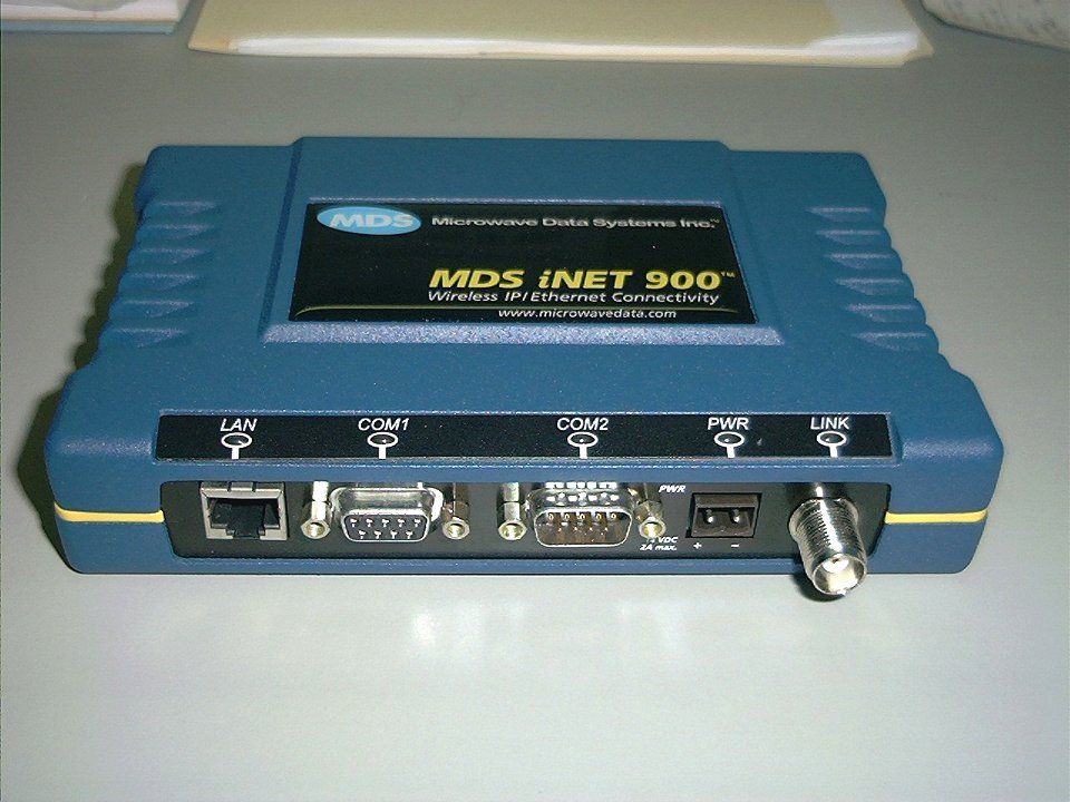
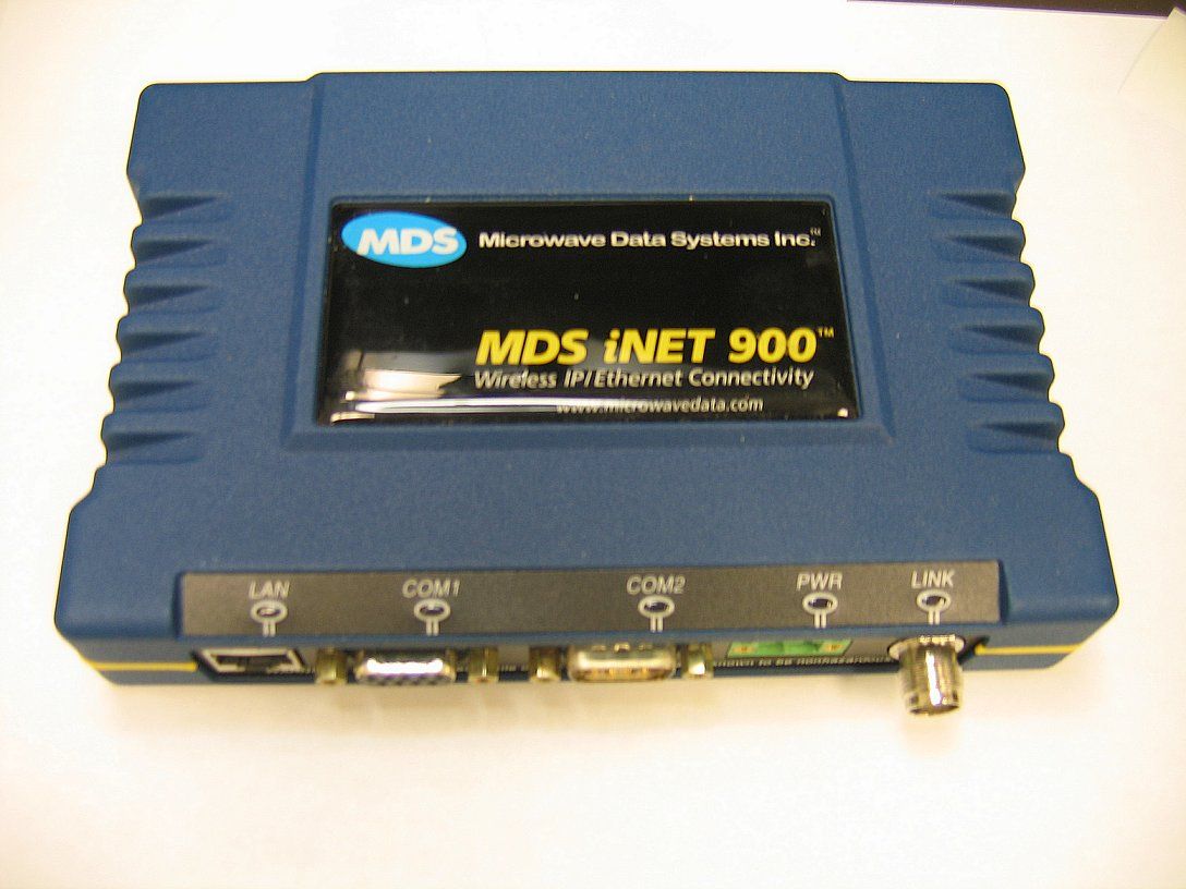
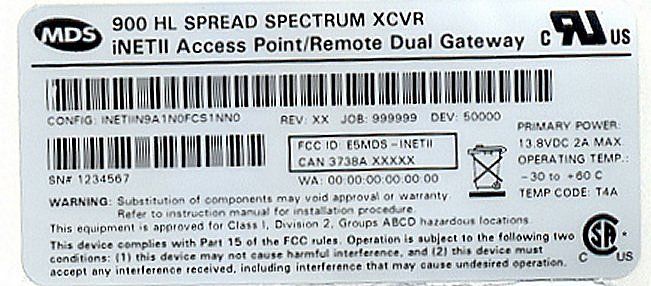
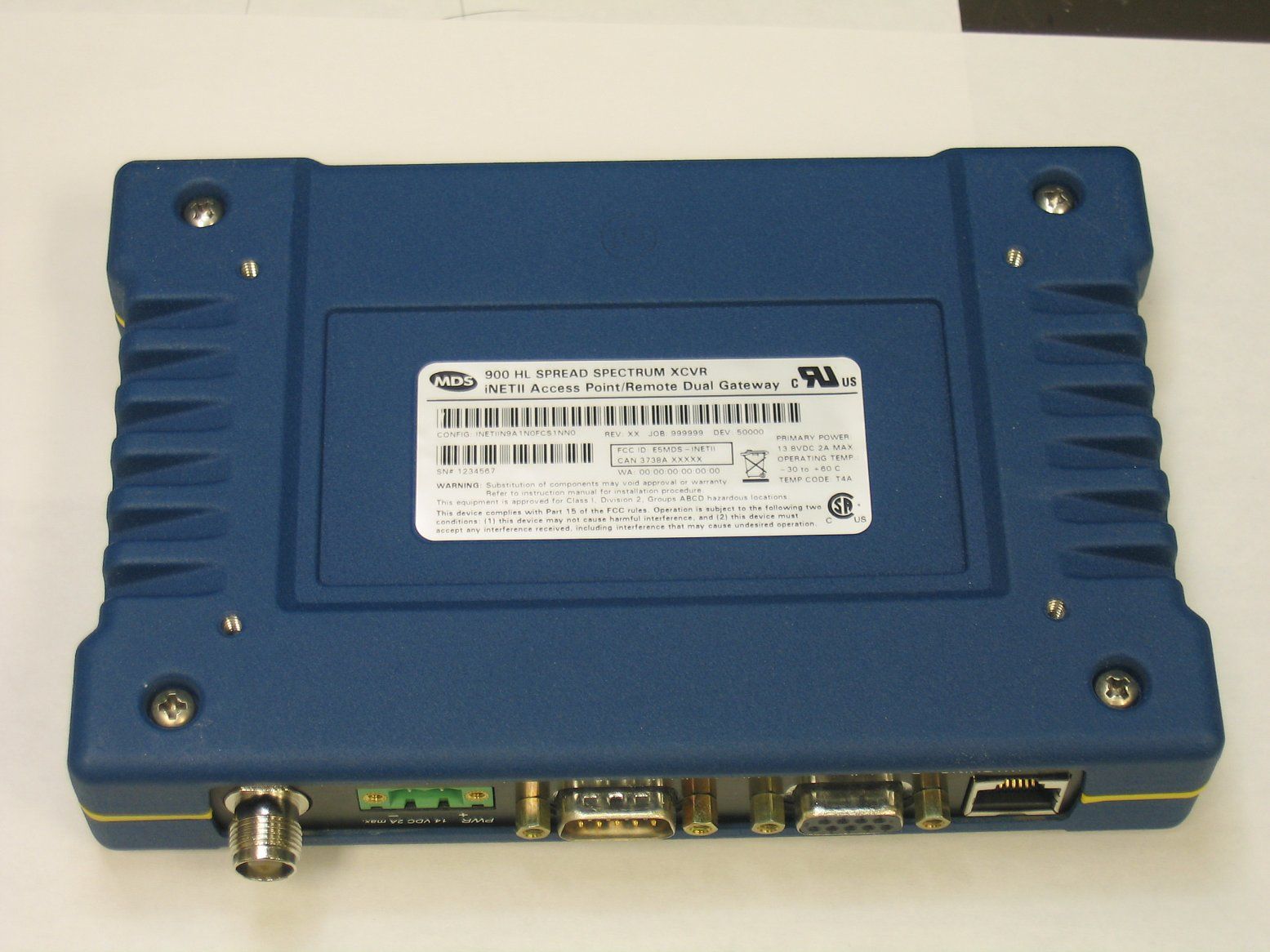
E5MDS-INETIIWireless IP/Ethernet Transceiver
GE MDS, LLC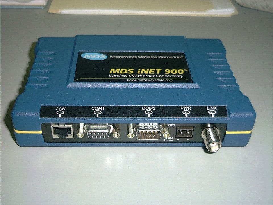
Click to zoom
Application Details
- Equipment Class
- DTS - Digital Transmission System
- Date of Grant
- Jan 10, 2006
- Application Purpose
- Original Equipment
- Date of Application
- Jan 10, 2006
- Equipment Note
- Wireless IP/Ethernet Transceiver
- Frequency Range
- 902.81650000 - 927.50350000
- Company
- GE MDS, LLC
- Country
- United States
Documents & Files
Document Text
Text extracted from the exhibit documents filed with the FCC. Open a document above to read the original.
Users Manual
User s Guide MDS 05-2806A01, Rev. E.1 DECEMBER 2005 Wireless IP/Ethernet Transceiver Firmware Release 4 MDS iNET 900 ™ Series Microwave Data Systems Inc. POWER SUPPLY 13.8 VDC @ 580 mA (Max.) (10.5–30 Vdc) Negative Ground Only DATA TERMINAL EQUIPMENT OR LAN/WAN COMPUTER W/TERMINAL EMULATOR TRANSCEIVER LOW-LOSS FEEDLINE QUICK-ST QUICK-ST ART INSTRUCTIONS ART INSTRUCTIONS ANTENNA SYSTEM INSTALLATION SUMMARY Step 1 – Mount the Transceiver Step 2 – Install the Antenna Step 3 – Measure & Connect Primary Power (10.5–30 Vdc) Step 4 – Review the transceiver’s Configuration Device Mode—Access Point, or Remote (Default) Network Name—Unique name for each radio network. Required for Remotes to associate with Access Point. IP Address—Must be a unique number to allow for IP access through the Ethernet Port. NOTE: A unique IP address is essential to access the browser-based Management System. RF Output Power—Adjust as necessary for regulatory compliance. (Default = 1 Watt /+30 dBm) Password—Used for remote access and some Management System features. (Default = admin) Step 5 – Connect the Data Equipment Connect the data equipment to data port(s): •LAN—10BaseT Ethernet-compatible equipment: Ethernet Hub (Straight-Through Cable); Ethernet Node (Crossover) •COM2—Serial, RS/EIA-232 compatible equipment •COM1—Management System (Default); Serial (Alternate) The Management System can be accessed through the COM1 Port using a terminal session on a PC. The basic items listed below, along with many other parameters & tools can be accessed through this method. HTTP, Telnet access, and changing some parameters are controlled by password. BASIC CONFIGURATION DEFAULTS Step 6 – Check for Normal Operation •Observe the transceiver LED status panel for the proper indications. In a normally operating system, the following LED indications will be seen within 30 seconds of power-up: PWR—Lights continuouslyLAN—On or blinks intermittently LINK— On or blinks intermittently (Remotes: if associated) •Use PING command to test basic data link integrity between Access Point and Remotes. •If the PING command is successful, connect the RTU/data equipment to the data port and verify normal operation. •If the LINK LED on Remotes is not on after 20 to 30 seconds, the unit has failed to associate with the Access Point. It may be necessary to reposition or redirect the radio’s antenna for better reception/signal strength. •Check connected data equipment for normal operation TYPICAL INSTALLATION Detailed instructions for setting transceiver parameters are contained in Section 3 of this manual. VALUES/RANGE • Remote • Access Point • 1–8 alphanumeric characters • Case-sensitive; can be mixed case • 1–16 alphanumeric characters • Case-sensitive; can be mixed case Contact your Network Administrator 20–30 dBm @ 50Ω (0.1–1.0 Watt) DEFAULT Remote admin (lower case) "Not Programmed" 192.168.1.1 +30 dBm (1.0 Watt) ITEMMGT SYSTEM MENU Device ModeNetwork Configuration Unit PasswordDevice Information Network NameNetwork Configuration IP AddressNetwork Configuration RF Output PowerRadio Configuration MDS 05-2806A01, Rev. E.1MDS iNET 900 Series User’s Guidei Contents 1 PRODUCT OVERVIEW AND APPLICATIONS ......... 1 1.1 PRODUCT DESCRIPTION............................................................................................. 3 1.1.1 Model Offerings ................................................................................................................... 5 1.2 APPLICATIONS ..............................................................................................................5 1.2.1 Wireless LAN ....................................................................................................................... 5 1.2.2 Point-to-Point LAN Extension .............................................................................................. 6 1.2.3 Backhaul for Serial Radio Networks ....................................................................................6 1.2.4 Multiple Protocols and/or Services ...................................................................................... 7 1.2.5 Wireless LAN with Mixed Services ......................................................................................8 1.2.6 Upgrading Older Wireless Network with Serial Interfaces ................................................... 9 1.2.7 High-Speed Mobile Data ................................................................................................... 10 1.3 NETWORK DESIGN CONSIDERATIONS .................................................................... 10 1.3.1 Extending Network Coverage with Repeaters ................................................................... 10 1.3.2 Protected Network Operation using Multiple Access Points .............................................. 12 1.3.3 Collocating Multiple Radio Networks ................................................................................. 13 1.4 MDS SECURITY SUITE ............................................................................................... 14 1.4.1 Early Warning via SNMP Traps ......................................................................................... 15 1.5 ACCESSORIES ............................................................................................................ 15 2 TABLETOP EVALUATION AND TEST SETUP ....... 17 2.1 OVERVIEW ................................................................................................................... 19 2.2 STEP 1—INSTALL THE ANTENNA CABLING............................................................. 19 2.3 STEP 2—MEASURE & CONNECT THE PRIMARY POWER ...................................... 20 2.4 STEP 3—CONNECT PC TO THE TRANSCEIVER ...................................................... 20 2.5 STEP 4—REVIEW TRANSCEIVER CONFIGURATION............................................... 21 2.5.1 Getting Started ......................................................................…
Text truncated - open the document above for the full version.
Cover Letter(s)
RE: Microwave Data Systems FCC ID: E5MDS-INETII 1) The product literature mentions upgradable firmware by the user. Please note that adjustments to radio parameters such as frequencies and other parameters are not allowed under 15.15. Section 15.15(b) prohibits adjustments of any control by the user that will cause operation of a device in violation of the regulations. Accordingly, any proposal to allow the end user to choose extended channels on frequencies outside of an allowable frequency band in the USA is not acceptable. For example, a WLAN device operating according to Section 15.247 on channels 1- 11 between 2.4 - 2.483.5 GHz must not have any user controls or software to allow the device to operate on channels 12 and 13 which are outside of the allowed USA band. Please explain how this device is compliant to this requirement for all bands of operation. Please refer to the document “MDS Response to ATCB.pdf” in which the manufacturer addresses these issues. 2) Internal photographs should show the top and bottom of all boards. Please correct. Internal photographs have been uploaded. 3) Please explain compliance to 15.203 requirements. Even though the EUT may contain a non- standard connector, other connectors (i.e. at the antenna) appear not to be. If professional installation is being requested for this device, this requires a cover letter requesting and justifying how the applicant ensures professional installation to be provided. The letter should address the following 3 items: a) Marketing example: The device cannot be sold retail, to the general public or by mail order. It must be sold to dealers or have strict marketing control. b) Requires professional installation; examples: - installation must be controlled. - installed by licensed professionals ( EUT sold to dealer who hire installers) - installation requires special training ( special programming, access to keypad, field strength measurements made) What is unique, sophisticated, complex, or specialized about your equipment which REQUIRES it to be installed by a professional installer? c) Application example: -The intended use is generally not for the general public. It is generally for industry/commercial use. Please refer to the document “MDS Response to ATCB.pdf” in which the manufacturer addresses these issues. 4) External photographs should also show the front of the unit. Please correct. See “external view-top.jpg” 5) Maximum measured power was 741 mW, while the product literature and operational description cite 1 W. The FCC expects devices to be tested as worse case in maximum output level. Please explain/review/correct as necessary. Please refer to the document “MDS Response to ATCB.pdf” in which the manufacturer addresses these issues. 6) The theory of operational also cites frequency hopping (page 3) while the application appears to cite DTS. Is this a hybrid transmitter? Are the modes discrete operation or simultaneous (hybrid). Please clearly denote what this device is and how it is being approved. Please refer to that attachment as well for guidance from the FCC. Please note that 2 discrete modes would require a composite application and much more additional information to support the frequency hopping requirements and theory. Response: The theory of operation has been corrected. This is only a DTS device and not a hopper and all references to being a hopper have been removed. 7) While MPE calculations were provided, there is not a comparison to any limits, or explanation of results relative to required distances. Please correct. Response: Calculations showing the exposure level at 20cm and the minimum separation distance (23cm) to meet the correct limits have been uploaded. The 23cm separation is also referenced in the user manual. 8) It appears that possibly 12.1 dBi applies to the yagi (from antenna information) or 12.2 dBi according to report, however we could simply be misreading all the data on antennas provide. Please clarify antennas covered by this application and please adjust the MPE as appropriate. Note much of the information provided showed antennas for different bands of operation, etc. Response: I have highlighted the antennas that were used for the radiated spurious test. Revised antenna data sheets have been uploaded. 9) A lot of antenna information and data sheets were provided, but without guidance to the specific antennas being used. Please provide further information as necessary as the antenna information appears to cite many antennas that would not be applicable as well. Response: Please refer to response# 8 10) Please explain the reference to 9.2 dBi, 2 dBd on page 8 of the report. Response: That was a typo should have been 7dBd. It has been corrected. 11) There is not enough information to support actual lowest and highest tunable channel frequencies. Please provide further information as necessary. Response: By looking at the Occupied bandwidth plots the data will show that the lowest frequency setting will be 902.8 MHz and the highest will be 927.5 MHz. 12) Note 2 on page 36 is incorrect or worded incorrectly regarding PSD testing. Please note that there are options and methods for power. You appeared to have used, Option 2, method 1. This would imply that PSD option 2 should be used. Please review/correct as necessary. Power was measured using RB=VB=3MHz, with RB > EBW (26dB bandwidth = 1.5MHz), zero span and power averaging enabled with sample detector. This corresponds to Option 2, method 2 of the FCC’s published methods. The test data note 1 has been corrected to reference the option and method correctly. PSD was measured using option 2 to match option used for the power measurement. Note 2 beneath the PSD data table had been updated to reference the option rather than method. 13) Test photos only support Yagi tesing. Are photos for omni antennas available? Response: Photos have been uploaded for the Omni antenna. 14) A users manual exhibit has yet to be provided, so FCC state…
Text truncated - open the document above for the full version.
Cover Letter(s)
RE: Microwave Data Systems FCC ID: E5MDS-INETII 1) It appears that the yagi may actually be 12.2 dBi which will slightly affect the MPE exhibit. Please correct. MPE has been changed to reflect 12.2 dBi. 2) Response 8 from MDS suggests power is reduced only when > 9 dBi. However power data suggests that omni’s also have reduction for 6 – 9 dBi. Please comment/review as necessary. The manual sates in page 134 tables 5-2 & page 135 section 5.1.5 and the 1 st note state that the power is to be reduced if antenna gain is > 6dBi. The power data tries to show compliance for each type and gain antenna. In the power data Run# 2 please refer to note 3 as to what was our intent of the power tables. 3) The frequencies shown in this application appear to be 902.8 – 927.5 MHz based upon your response. However this appears to be backward compatible with previous systems and page 157-158 of the users manual suggests this should be 902.5 – 927.5035. Please confirm with the manufacturer the intended maximum and minimum tunable channels. Most of the previous applications appear to be approved for 902.2 – 927.8 or 902.5 – 927.5. Either way, it appears that a one or more channels may not be available in this system or tested as requires by FCC rules. Please review/comment. Updated manual uploaded. Channels clarified in table of the INET and the INETII table 6.4 on page 149. 4) Information on pages 136 – 145 of the manual suggest adjusting power for compensation of cable loss. However please note testing at maximum output for each type of antenna has been approved, regardless of cable loss. Please comment as necessary. Clarification of this for the iNETII in the manual may be desirable since the manual suggest that with higher cable loss, different settings may be used to meet +36 dBi. A new table was made on page 134, table 5-2 lists antennas and required feedline loss to stay in compliance with the +36dBm FCC limit, Then on table 5-3 it lists the specifics for the INET and INETII power settings. EUT was tested with a short feedline and maximum antenna for worst case. Then this suggest that we should be OK listing a minimum example feedline loss to show the limits. IC 5) The newly provided RSS-102 declaration was only the IC REL listing letter, note the new RSS- 120 attestation. Please review and correct. Uploaded correct RSS-102 declaration form. Regards, Juan Martinez
Cover Letter(s)
175 Science Parkway, Rochester, New York 14620 USA (585) 242-9600 Phone (585) 242-9620 Fax November 12th, 2005 FEDERAL COMMUNICATIONS COMMISSION 7435 Oakland Mills Road Columbia, MD 21046 U.S.A. Subject: Authority to Act as an Agent to FCC Applicant: Microwave Data Systems Inc. Product: iNET-II antenna and transceiver system FCC ID: E5MDS-INETII Dear Sir/Madam, I hereby appoint Elliott Labs of Sunnyvale Calif. to act as my agent in preparation of this application to F.C.C. for authorization of equipment under F.C.C. Rules. I also certify that the information provided, properly described the device or system for which authorization is required. If you have any queries, please do not hesitate to contact me at 585 242-8440: Yours truly, Dennis McCarthy Agency Compliance Engineer Microwave Data Systems 175 Science Parkway Rochester NY 14620 Phone (585) 242-8440 Email [email protected]
Cover Letter(s)
175 Science Parkway, Rochester, New York 14620 USA (585) 242-9600 Phone (585) 242-9620 Fax December 20th, 2005 ATCB 6731 Whittier Ave Mclean VA 22101 Subject: Response to Dec 19th 2005 iNETII review questions Applicant: Microwave Data Systems Inc. Product: MDS iNETII High Speed version of iNET (Note: marketing wishes the name with a lower case iNETII ) Model: MDS iNETII FCC ID: E5MDS-iNETII Dear Timothy: Thanks for your questions on the iNETII FCC grant. I hope these answers will satisfy your concerns. Question: 1) The product literature mentions upgradable firmware by the user. Please note that adjustments to radio parameters such as frequencies and other parameters are not allowed under 15.15. Section 15.15(b) prohibits adjustments of any control by the user that will cause operation of a device in violation of the regulations. Accordingly, any proposal to allow the end user to choose extended channels on frequencies outside of an allowable frequency band in the USA is not acceptable. For example, a WLAN device operating according to Section 15.247 on channels 1-11 between 2.4 - 2.483.5 GHz must not have any user controls or software to allow the device to operate on channels 12 and 13 which are outside of the allowed USA band. Please explain how this device is compliant to this requirement for all bands of operation Answer: The firmware (software) upgrades will include things like, encryption support, Radius login, Customer specific serial interface software support, Security upgrades, Software bug upgrades etc. In all cases the operating frequency of 902-928MHz is limited to hardware and can’t be changed by the end user. There is no control to the user that will allow the customer to operate the radio outside the certified operating range. The software control of selectable channels will only allow the user to operate in the range of 902-928MHz according to the FCC part 15 DTS rules. 2) Internal photographs should show the top and bottom of all boards. Please correct. Answer: See pictures included. 3) Please explain compliance to 15.203 requirements. Answer: All MDS products are designed and marketed to business industrial customers, there are no cases in which our products are sold to the general public IE: consumer. Professional installation is required for 100% of our marketed products. MDS has a trained staff of professional field installers, trained Full Service Partners, and trained OEM customers that integrate our modular approved products into their OEM products. A, TNC connector is used for the RF interface, this is allowed by claiming professional installation. Our technical services department has certification courses for all our product’s, all our service and installation personnel are certification trained. MDS is requesting professional installation for this version of the iNETII. The existing approved iNET is FCC granted and this is listed as professional installation. The higher speed version of this radio (iNETII) will operate at speeds up to 1mbps. If you wish to visit our corporate website, it clearly shows MDS is an industrial supplier of “high end” wireless solutions. www.microwavedata.com At no time do we intend to sell goods to the general consumer. 4) External photographs should also show the front of the unit. Answer: See pictures included. 5) Maximum measured power was 741 mW, while the product literature and operational description cite 1 W. The FCC expects devices to be tested as worse case in maximum output level. Answer: The iNETII was tested and approved at 741mw under the DTS rules. This RF power is close to 1 watt in dBm terms, +28.69dBm, our software locks the forward power control to this limit and hardcodes this into RAM. The text in our marketing data sheet will be changed to 741mw. See attached new iNETII data sheet 6) Labeling for IC should show proper IC number Answer: See pictures included of updated label 7) Please verify how they desire to list the model for IC. The form cites INETII, while the label of the device cites iNETII. Answer: (Note: marketing wishes the name with a lower case iNETII ) The IC application attached has been updated to iNETII. For all future correspondence the lower case I should be used in the model string. Thanks 8) MDS is requesting Professional installation for this iNETII product. “Professional Installation attestation” the iNETII’s output power is reduced by the Professional installer when antenna gains exceed 9dBi are used to maintain compliance with the 36dBi power limitation If you have any questions please feel free to contact me anytime. Happy Holidays Cheers Dennis Dennis McCarthy Agency Compliance Engineer Microwave Data Systems 175 Science Parkway Rochester NY 14620 (585) 242-8440 email [email protected]
Cover Letter(s)
175 Science Parkway, Rochester, New York 14620 USA (585) 242-9600 Phone (585) 242-9620 Fax November 9th, 2005 FEDERAL COMMUNICATIONS COMMISSION 7435 Oakland Mills Road Columbia, MD 21046 U.S.A. Subject: Request for withholding from public disclosure the schematic diagrams and system block diagrams pursuant to an application for certification. Applicant: Microwave Data Systems Inc. Product: iNET-II Data Transceiver (DTS rules) Model: iNETII FCC ID: E5MDS-INETII Dear Sir/Madam, We, Microwave Data Systems, would like to request that the schematic diagrams, system block diagram, and Theory of Operation submitted with the application for certification be withheld from public disclosure as per Section 0.459 of FCC Rules. This request is made under the provisions of Section 0.457(d) of the Commission's Rules, and Section 552(b)(4) of the Freedom of Information Act. These sections authorize as a withholding from public inspection materials which would be privileged as a matter of law if retained by the person submitting them, and materials which would not customarily be released to the public by that person. If you have any queries, please do not hesitate to contact me at 585 242-8440: Yours truly, Dennis McCarthy Agency Compliance Engineer Microwave Data Systems 175 Science Parkway Rochester NY 14620 Phone (585) 242-8440 Email [email protected]
Operational Description
900 MHz Omnidirectional Fiberglass Base Station Antenna Series The MFB 900 MHz omnidirectional antennas are base matched, half wave antenna encapsulated in a heavy duty fiberglass radome with a thick walled aluminum mounting base for reliable long term use. All models are DC grounded. Features and Benefits: •White UV resistant pultruded fiberglass radome. Protects the antenna from the elements. •Thick walled aluminum mounting base. Helps prevent oscillation that could affect the quality of the transmission. •Available in various gain configurations to fit various application requirements. •Wideband models available covering all 890-960 MHz bands, without additional tuning required. 900 MHz Omnis - MFB Series General Specifications: 900 MHz fiberglass omnidirectional antenna series Radome Material: .65” pultruded white fiberglass Polarization: Vertical Lightning Protection: DC grounded Nominal Impedance: 50 Ohms Mounting Method: (sold separately) MMK1 light duty mast mount for antennas under 30” tall MMK3 light duty mast mount for antennas over 30” tall MMK4 heavy duty mast mount MMK6 cast mount bracket MBSWM wall mount bracket for antennas over 30” tall (two are required) Mounting Base Diameter: 1-5/16” Termination: N female - unity and 3 dB models N male with 16” jumper - 5 dB and 7dB models Reverse Polarity TNC - models ending in RPC The MFB 900 MHz omnidirectional antennas are encapsulated in a heavy-duty fiberglass radome for reliable, long term performance under the toughest weather conditions. MMK1 Mount MMK3 Mount MMK4 Mount MMK6 Mount 267 PCTEL Antenna Products Group, Inc. ORDER (800) 323-9122 http://www.maxrad.com Model # Wind Survival Lateral Thrust @ Rated Wind Bending Moment @ Rated Wind HeightWeight MFB8960100 mph2.3 lbs1.4 ft-lbs14” (355.4 mm)0.75 lbs (0.34 kg) MFB9150100 mph2.3 lbs1.4 ft-lbs14” (355.4 mm)0.75 lbs (0.34 kg) MFB9300100 mph2.3 lbs1.4 ft-lbs14” (355.4 mm)0.75 lbs (0.34 kg) MFB9380100 mph2.3 lbs1.4 ft-lbs14” (355.4 mm)0.75 lbs (0.34 kg) MFB8963100 mph4.3 lbs4.7 ft-lbs26” (660.4 mm)1.25 lbs (0.56 kg) MFB9153100 mph4.3 lbs4.7 ft-lbs23” (590.5 mm)1.25 lbs (0.56 kg) MFB9303100 mph4.3 lbs4.7 ft-lbs26” (660.4 mm)1.25 lbs (0.56 kg) MFB9383100 mph4.3 lbs4.7 ft-lbs26” (660.4 mm)1.25 lbs (0.56 kg) MFB8965100 mph8.0 lbs14.2 ft-lbs48” (1219.2 mm)1.75 lbs (0.79 kg) MFB9155100 mph8.0 lbs14.2 ft-lbs48” (1219.2 mm)1.75 lbs (0.79 kg) MFB9305100 mph8.0 lbs14.2 ft-lbs48” (1219.2 mm)1.75 lbs (0.79 kg) MFB9385100 mph8.0 lbs14.2 ft-lbs48” (1219.2 mm)1.75 lbs (0.79 kg) MFB8967100 mph15.8 lbs62.5 ft-lbs96” (2438.4 mm)4.00 lbs (1.81 kg) MFB9157100 mph15.8 lbs62.5 ft-lbs96” (2438.4 mm)4.00 lbs (1.81 kg) MFB9307100 mph15.8 lbs62.5 ft-lbs96” (2438.4 mm)4.00 lbs (1.81 kg) MFB9387100 mph15.8 lbs62.5 ft-lbs96” (2438.4 mm)4.00 lbs (1.81 kg) MFB9153RPC100 mph4.3 lbs4.7 ft-lbs23” (590.5 mm)1.25 lbs (0.56 kg) MFB9153STRPC100 mph4.3 lbs4.7 ft-lbs23” (590.5 mm)1.25 lbs (0.56 kg) MFB9157RPC100 mph15.8 lbs62.5 ft-lbs96” (2438.4 mm)4.00 lbs (1.81 kg) MFBW8903100 mph4.3 lbs4.7 ft-lbs26” (660.4 mm)1.25 lbs (0.56 kg) MFBW8905100 mph8.0 lbs14.2 ft-lbs48” (1219.2 mm)1.75 lbs (0.79 kg) Model # Frequency Range Factory Tuned Frequency Gain Bandwidth @ 1.5:1 VSWR Vertical Beamwidth @ 1/2 Power Maximum Power MFB8960896-940 MHz898 MHzUnity40 MHz75°150 Watts MFB9150902-928 MHz915 MHzUnity20 MHz75°150 Watts MFB9300928-932 MHz930 MHzUnity5 MHz75°150 Watts MFB9380896-940 MHz938 MHzUnity40 MHz75°150 Watts MFB8963896-940 MHz898 MHz3 dB30 MHz40°150 Watts MFB9153902-928 MHz915 MHz3 dB20 MHz40°150 Watts MFB9303928-932 MHz930 MHz3 dB5 MHz40°150 Watts MFB9383896-940 MHz938 MHz3 dB30 MHz40°150 Watts MFB8965896-940 MHz898 MHz5 dB20 MHz22°150 Watts MFB9155902-928 MHz915 MHz5 dB20 MHz22°150 Watts MFB9305928-932 MHz930 MHz5 dB5 MHz22°150 Watts MFB9385896-940 MHz938 MHz5 dB20 MHz22°150 Watts MFB8967896-940 MHz898 MHz7 dB20 MHz17°150 Watts MFB9157902-928 MHz915 MHz7 dB20 MHz17°150 Watts MFB9307928-932 MHz930 MHz7 dB5 MHz17°150 Watts MFB9387896-940 MHz938 MHz7 dB20 MHz17°150 Watts MFB9153RPC902-928 MHz915 MHz3 dB20 MHz40°150 Watts MFB9153STRPC902-928 MHz915 MHz3 dB20 MHz40°150 Watts MFB9157RPC896-940 MHz915 MHz7 dB20 MHz17°150 Watts MFBW8903890-960 MHz925 MHz3dB70 MHz40°150 Watts MFBW8905890-960 MHz925 MHz5dB70 MHz22°150 Watts Electrical Specifications Specifications Mechanical Specifications 268 PCTEL Antenna Products Group, Inc. ORDER (800) 323-9122 http://www.maxrad.com
Operational Description
Page 1 of 3 COMPONENT SPECIFICATION File: MAXRAD Yagi 10dBd data sheet97 - 3194AxxRevF.doc 97 - 3194AxxRevE.doc Printed: 12/06/05 10:39 AM11/29/05 07:22 AM 10/31/05 10:39 AM Printed: 12/6/2005 10:39 AM 4/16/2003 10:06 AM Electronically Controlled Document Verify hardcopy is latest revision prior to use 97-3194Axx Rev: E DS, CLEARWAVE ANTENNAS (MAXRAD) xx Rev MHz DESCRIPTION TYPE MANUFACTURER MFG. NUMBER 01 01A 01B 01C A 406-430 Mhz 3 Element, 6.5dbd, N Female term. 3 Element, 6.5dbd, 10 ft. LMR400 coax, type N male termination. Same antenna but 15 ft. coax Same antenna but 25 ft. coax YAGI END BOOM W/mounting hardware MAXRAD * Z944 Z944A Z944B Z944C 02 02A 02B 02C A 406-430 Mhz 6 Element, 10dbd, N Female term. 6 Element, 10dbd, 10 ft. LMR 400 coax, type N male termination. Same antenna but 15 ft coax Same antenna but 25 ft coax YAGI END BOOM W/mounting hardware MAXRAD * Z943 Z943A Z943B Z943C 03 03A 03B 03C A 430-450 Mhz 3 Element, 6.5dbd, N Female term. 3 Element, 6.5dbd, 10 ft. LMR 400 coax, type N male termination. Same antenna but 15 ft coax. Same antenna but 25 ft coax. YAGI END BOOM W/mounting hardware MAXRAD * Z1331 Z1331A Z1331B Z1331C 04 04A 04B 04C A 430-450 Mhz 6 Element, 10dbd, N Female term. 6 Element, 10dbd, 10 ft LMR 400 coax, type N male termination. Same antenna but 15 ft coax. Same antenna but 25 ft coax YAGI END BOOM W/mounting hardware MAXRAD * Z1330 Z1330A Z1330B Z1330C 05 05A 05B 05C A 450-470 Mhz 3 Element, 6.5dbd, N Female term. 3 Element, 6.5dbd, 10 ft LMR 400 coax, type N male termination. Same antenna but 15 ft coax. Same antenna but 25 ft coax YAGI END BOOM W/mounting hardware MAXRAD * Z1333 Z1333A Z1333B Z1333C 06 06A 06B 06C A 450-470 Mhz 6 Element, 10dbd, N Female term. 6 Element, 10dbd, 10 ft LMR 400 coax, type N male termination. Same antenna but 15 ft coax. Same antenna but 25 ft coax YAGI END BOOM W/mounting hardware MAXRAD * Z1332 Z1332A Z1332B Z1332C Page 2 of 3 COMPONENT SPECIFICATION 97-3194Axx Rev: E97 - 3194Axx Rev: E 97 - 3194Axx Rev: ED DS, CLEARWAVE ANTENNAS (MAXRAD) Printed: 12/06/05 10:39 AM11/ 29/05 07:22 AM 10/31/05 10:39 AM Electronically Controlled Document Verify hardcopy is latest revision prior to use 13 13A 13B 13C A 902-960 Mhz 3 Element, 6.4dbd, N Female term. 3 Element, 6.4dbd, 10 ft LMR 400 coax, type N male termination. Same antenna but 15 ft coax. Same antenna but 25 ft coax YAGI END BOOM W/mounting hardware MAXRAD * Z942 Z942A Z942B Z942C 14 14A 14B 14C A 902-960 Mhz 6 Element, 10dbd, N Female term. 6 Element, 10dbd, 10 ft LMR 400 coax, type N male termination. Same antenna but 15 ft coax. Same antenna but 25 ft coax YAGI END BOOM W/mounting hardware MAXRAD * Z941 Z941A Z941B Z941C 14D A B 902-960 Mhz 6 Element, 10dbd, N Female term, 20FT LMR 400 Coax, Type N Male Termination YAGI END BOOM W/mounting hardware MAXRAD * Z941J H 15 A 902-960 Mhz 6 Element,10db, N Fmale term w/MYK17 YAGI END BOOM W/ MYK17 MAXRAD Z1488 16 A 902-928 Mhz 5 dBd 22º., VBW, N male, 16” jumper Omnidirectional w/MMK12 mount MAXRAD Z1347 17 A 902-928 Mhz 7 dBd, 17º, VBW N male 16” jumper Omnidirectional w/MMK12 mount MAXRAD Z1609 18 A 406-430 Mhz 5 dBd Omnidirectional N male 16” jumper Omnidirectional w/MMK12 mount MAXRAD Z1342 19 A 430-450 Mhz 5 dBd Omnidirectional N male 16” jumper Omnidirectional w/MMK12 mount MAXRAD Z1343 20 A 450-470 Mhz 5 dBd Omnidirectional N male 16” jumper Omnidirectional w/MMK12 mount MAXRAD Z1344 21 A 890-960 Mhz 3 dBd Omnidirectional N Female Omnidirectional w/MMK12 mount MAXRAD Z1349 22 A 890-960 Mhz 5 dBd Omnidirectional N male 16” jumper Omnidirectional w/MMK12 mount MAXRAD Z1350 23 A 928-960 Mhz 7 dBd Omnidirectional N male 16” jumper Omnidirectional w/MMK12 mount MAXRAD Z1351 Page 3 of 3 COMPONENT SPECIFICATION 97-3194Axx Rev: E97 - 3194Axx Rev: E 97 - 3194Axx Rev: ED DS, CLEARWAVE ANTENNAS (MAXRAD) Printed: 12/06/05 10:39 AM11/ 29/05 07:22 AM 10/31/05 10:39 AM Electronically Controlled Document Verify hardcopy is latest revision prior to use 24 A 902-960 Mhz 6 Element, 10dbd, (12.1dBi) with 20 ft LMR 400 coax,, attached cable grip and conduit fitting lock nut heat shrunk to boom, end mount N-Male c…
Text truncated - open the document above for the full version.
Contact Information
Applicant
John Barenys(Senior Operations Manager)
Technical Contact
Elliott Laboratories Inc.Juan Martinez
[email protected]408-245-7800
684 West Maude Ave. · Sunnyvale, California · United States
Non-Technical Contact
Elliott Laboratories Inc.Juan Martinez
[email protected]408-245-7800
Test Firm
Elliott Laboratories LLCDavid Bare
Technical Specifications
| # | Rule Parts | Frequency Range | Power Output |
|---|---|---|---|
| 1 | 15C | 902.8165 MHz - 927.5035 MHz | 741.00 mW |
Other Applications from GE MDS, LLC

E5MDS-NET9S
Jul 13, 2023Frequency Hopping Radio
Equipment Class
DSS - Part 15 Spread Spectrum Transmitter
E5MDS-NET9L
Jul 11, 2023Frequency Hopping Radio
Equipment Class
DSS - Part 15 Spread Spectrum Transmitter
E5MDS-LN900
Jan 27, 2016Industrial Radio Module
Equipment Class
TNB - Licensed Non-Broadcast Station Transmitter
E5MDS-SDM4
Aug 20, 2015MDS SDM4 Licensed Spectrum Module
Equipment Class
TNB - Licensed Non-Broadcast Station Transmitter
E5MDS-LN400
Jul 09, 2015Industrial Radio Module
Equipment Class
TNB - Licensed Non-Broadcast Station Transmitter