E5MDS-LEDR700SDigital Radio
GE MDS, LLC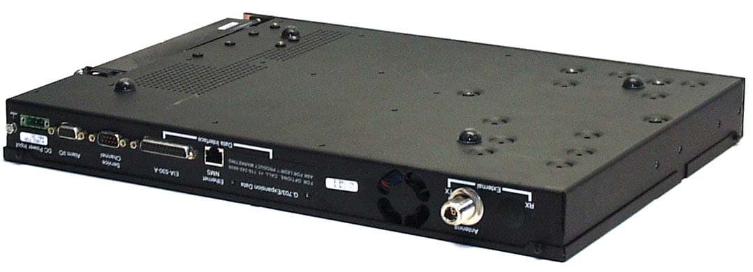
Click to zoom
Application Details
- Equipment Class
- TNB - Licensed Non-Broadcast Station Transmitter
- Date of Grant
- Mar 20, 2003
- Application Purpose
- Original Equipment
- Date of Application
- Mar 20, 2003
- Equipment Note
- Digital Radio
- Frequency Range
- 792.00000000 - 794.00000000
- Company
- GE MDS, LLC
- Country
- United States
Documents & Files
Document Text
Text extracted from the exhibit documents filed with the FCC. Open a document above to read the original.
Users Manual
Installation & Operation Guide P/N 05-3627A01, Rev. D JANUARY 2003 Covering LEDR 400S/F, 700S, 900S/F, 1400S/F Models Including Protected (1+1) and Space Diversity Versions LEDR Series Digital Microwave Radios Microwave Data Systems Inc. LEDR Series radios are supplied from the factory in matched pairs and are configured to user’s specifi- cations. There are a few steps necessary to place the pair on-the-air communicating with each other. Once this is done, system-specific parameters will need to be reviewed and changed to match your requirements. Below are the basic steps for installing the LEDR radio. For more detailed instructions, please see “INITIAL STARTUP AND CONFIGURATION” on page 25. When making cable connections, refer to Section 3.6, Rear Panel Connectors , on page 17 for a rear panel view of the radio. 1.Install and connect the antenna system to the radio • Ensure a path study has been conducted and that the radio path is acceptable. • Use good quality, low loss coaxial cable. Keep the cable as short as possible. • Preset directional antennas in the direction of desired transmission/reception. 2.Connect the data equipment to the rear panel data interface • The data interface should be an RJ-45 connector for Fractional-T1, Fractional-E1, or E1, and a DB-25 connector for EIA-530. • Verify the customer premises data equipment is configured as DTE. (By default, the LEDR radio is configured as DCE.) 3.Apply DC power to the radio • Verify that the line voltage matches the power supply input range (typically 24 Vdc or 48 Vdc). • The power connector is a three-pin keyed connector. The power source can be connected with either polarity. The center conductor is not connected. • Ensure the chassis Ground lug is connected to an appropriate ground point. 4.Change SUPER password and set up user access • Login to Network Management System, using the password SUPER . (See “login” on page 68 .) • Change the password using the PASSWD command. ( See “passwd” on page 72. ) • Set up required users, passwords and access levels using the USER command, as required. ( See “user” on page 86. ) 5.Set the radio’s basic configuration using front panel or Console interface • Set the transmit/receive frequencies ( TX xxx.xxxx / RX xxx.xxxx ) if they need to be changed from the factory settings. (See “freq” on page 59 .) • Refer to this manual for other configuration settings. 6.Verify and set the following parameters as necessary to allow data throughput and intercon- nection with the network. • RF transmit and receive frequencies. (See “freq” on page 59 .) • Radio modulation type and data rate parameters. ( See “modem” on page 71. ). • Data interface clocking. ( See “clkmode” on page 55. ). • Data framing. ( See “fstruct” on page 59. ). Quick-Start instructions continued on the rear cover of this manual. QUICK-START GUIDE MDS 05-3627A01, Rev. DLEDR Series I/O Guidei TABLE OF CONTENTS 1.0 INTRODUCTION .................................................................................................................. 1 1.1 Product Description ....................................................................................................................... 1 1.2 LEDR Features .............................................................................................................................. 2 1.3 Typical Applications ....................................................................................................................... 3 1.4 Protected Configuration ................................................................................................................. 3 2.0 MODEL NUMBER CODES................................................................................................... 4 3.0 HARDWARE INSTALLATION AND BASIC INTERFACE REQUIREMENTS ........................ 7 3.1 Introduction .................................................................................................................................... 7 3.2 General Requirements .................................................................................................................. 7 Site Selection ................................................................................................................................... 8 Terrain and Signal Strength ............................................................................................................. 8 On-the-Air Test ................................................................................................................................. 9 A Word About Interference............................................................................................................... 9 3.3 Antenna and Feedline Selection .................................................................................................. 10 Antennas........................................................................................................................................ 10 Feedlines ....................................................................................................................................... 11 3.4 Radio Mounting ........................................................................................................................... 13 Maximizing RSSI............................................................................................................................ 13 Attaching the Rack Mounting Brackets .......................................................................................... 13 3.5 Front Panel .................................................................................................................................. 14 Indicators, Text Display and Navigation Keys................................................................................. 14 Connectors..................................................................................................................................... 16 3.6…
Text truncated - open the document above for the full version.
Cover Letter(s)
175 Science Parkway, Rochester, New York 14620 USA (585) 242-8440 Phone (585) 242-9620 Fax March 20, 2003 Subject: response to the TCB’s LEDR400S questions Question 1: Updated the test specification to reflect the other frequencies that are approved. The attached file reflects this. Question 2: Ultratech will answer this question about the attenuator. Question 3: The final RF amplifying device is Q703, shown on schematic sheet 11 at grid 4F. This is a Mitsubishi MGF0911A GaAs FET. The source of the FET is grounded. An active bias control loop regulates the DC voltage on the Drain to +10VDC for all operating conditions. One section of Op-Amp U707 (sheet 11, grid 5F) senses the drain voltage on pin 12 and compares it to regulated 10 volts on pin 13. The op-amp output on pin 14 provides bias to the gate terminal with a nominal value of -2VDC. Drain current flows from the "+11.75V_KEY" source through 0.83 Ohms and choke L718 to the Drain. Nominal drain current is 2.1 Amps. Being a very linear class-A amplifier, these conditions are maintained over all output power levels whenever the TX keyline is asserted. When the TX keyline is non- asserted the "+11.75V_KEY" source is turned off by Q704 (sheet 11, grid 6B) Question 4: Transmit Frequency is determined by a frequency synthesizer consisting of Synthesizer Controller U710 (Sheet 10, grid 7C); Voltage Controlled Oscillator (VCO) U705 (Sheet 10, grid 5C); Temperature Compensated Crystal Oscillator (TCXO) Y601 (Sheet 9, grid 5D); and associated circuitry. Frequency Stability is determined by Y601 which has 1.5 part-per-million frequency stability. Spurious radiation is limited by the LC lowpass filter following the final RF amplifier. This filter consists of C823, L720, C824, L721, and C825 shown on sheet 11 at grids 3F and 4F. Transmit modulation is accomplished and controlled at the I.F. within QAM Modulator U501 shown on sheet 8 at grid 2G. U501 is a Broadcom BCM3033 QAM Modulator under full software control including modulation type and data rate. RF power is controlled by an active Transmit Gain Control (TGC) loop. The feedback and control portion of the TGC loop consists of a directional coupler to sample the output power (sheet 11, grid 3E); Detector CR700 (sheet 11, grid 3E); Op-Amp U707 (sheet 11, grid 3D); A-to-D Converter U106 (sheet 4, grid 7C); Microcontroller U101 (sheet 2, grid 4E), a D-to-A converter inside Demodulator U500 (sheet 8, grid 8G); Op-Amp U715 (sheet 10, grid 2C); DC amplifier Q702 (sheet 10, grid 3C); and PIN Diode Attenuator CR701 (sheet 10, grid 2E). The loop is under full software control with U101 providing the "brainpower". Questions 3 & 4 are answered by the RF design engineer. John Cmelko Sr. Development Engineer, RF TEL (585) 242-8483 FAX (585) 241-5590 E-mail [email protected] If you have any queries, please do not hesitate to contact me at 585 242-8440: Yours truly, Dennis McCarthy Agency Compliance Engineer Microwave Data Systems 175 Science Parkway Rochester NY 14620 Phone (585) 242-8440 Email [email protected]
Cover Letter(s)
American Telecommunications Certification Body Inc. 6731 Whittier Ave, McLean, VA 22101 March 19, 2003 RE: Microwave Data Systems, Inc. FCC ID: E5MDS-LEDR700S After a review of the submitted information, I have a few comments on the above referenced Application. 1) The frequency range given in the tune up procedure does not appear to match the 731/operational description and other documentation given in this application. Please explain. 2) The antenna conducted spurious emissions test appears to use an attenuator rated to 1.8 GHz only. The frequency range of this test extends beyond the frequency range for the attenuator used. Please provide information regarding the characteristics of the attenuator above 1.8 GHz. 3) Please provide information regarding the DC voltages/currents applied into the several elements of the final radio frequency amplifying device for normal operation over the power range. 4) Please provide information regarding the description of all circuitry and devices provided for determining and stabilizing frequency, for suppression of spurious radiation, for limiting modulation, and for limiting power. Timothy R. Johnson Examining Engineer Direct Phone: 404-414-8071 mailto: [email protected] The items indicated above must be submitted before processing can continue on the above referenced application. Failure to provide the requested information may result in application termination. Correspondence should be considered part of the permanent submission and may be viewed from the Internet after a Grant of Equipment Authorization is issued. Please do not respond to this correspondence using the email reply button. In order for your response to be processed expeditiously, you must submit your documents through the AmericanTCB.com website. Also, please note that partial responses increase processing time and should not be submitted. Any questions about the content of this correspondence should be directed to the sender.
Cover Letter(s)
175 Science Parkway, Rochester, New York 14620 USA (585) 242-9600 Phone (585) 242-9620 Fax November 13, 2002 FEDERAL COMMUNICATIONS COMMISSION 7435 Oakland Mills Road Columbia, MD 21046 U.S.A. Subject: Authority to Act as an Agent to FCC Applicant: Microwave Data Systems Inc. Product: MDS LEDR700S Model: LEDR700S FCC ID: E5MDS-LEDR700S Dear Sir/Madam, I hereby appoint UltraTech Engineering Labs Inc. (UltraTech) to act as my agent in preparation of this application to F.C.C. for authorization of equipment under F.C.C. Rules. I also certify that the information provided, properly described the device or system for which authorization is required. If you have any queries, please do not hesitate to contact me at 585 242-8440: Yours truly, Dennis McCarthy Agency Compliance Engineer Microwave Data Systems 175 Science Parkway Rochester NY 14620 Phone (585) 242-8440 Email [email protected]
Cover Letter(s)
175 Science Parkway, Rochester, New York 14620 USA (585) 242-9600 Phone (585) 242-9620 Fax November 13, 2002 FEDERAL COMMUNICATIONS COMMISSION 7435 Oakland Mills Road Columbia, MD 21046 U.S.A. Subject: Request for withholding from public disclosure the schematic diagrams and system block diagrams pursuant to an application for certification. Applicant: Microwave Data Systems Inc. Product: MDS LEDR700S (for the newly released guard band applications) Model: LEDR700S FCC ID: E5MDS-LEDR700S Dear Sir/Madam, We, Microwave Data Systems, would like to request that the schematic diagrams, system block diagram, Theory of Operation, Tune Up Information and Bill of Materials submitted with the application for certification be withheld from public disclosure as per Section 0.459 of FCC Rules. This request is made under the provisions of Section 0.457(d) of the Commission's Rules, and Section 552(b)(4) of the Freedom of Information Act. These sections authorize as a withholding from public inspection materials which would be privileged as a matter of law if retained by the person submitting them, and materials which would not customarily be released to the public by that person. If you have any queries, please do not hesitate to contact me at 585 242-8440: Yours truly, Dennis McCarthy Agency Compliance Engineer Microwave Data Systems 175 Science Parkway Rochester NY 14620 Phone (585) 242-8440 Email [email protected]
External Photos
ANNEX 3 – EXTERNAL EUT PHOTOS Microwave Data Systems Inc. MDS LEDR700S, Model LEDR700S FCC ID: E5MDS-LEDR700S A3 - 1 ANNEX 3 – EXTERNAL EUT PHOTOS Microwave Data Systems Inc. MDS LEDR700S, Model LEDR700S FCC ID: E5MDS-LEDR700S A3 - 2
Internal Photos
ANNEX 4 – INTERNAL EUT PHOTOS Microwave Data Systems Inc. MDS LEDR700S, Model LEDR700S FCC ID: E5MDS-LEDR700S A4 - 1 ANNEX 4 – INTERNAL EUT PHOTOS Microwave Data Systems Inc. MDS LEDR700S, Model LEDR700S FCC ID: E5MDS-LEDR700S A4 - 2 ANNEX 4 – INTERNAL EUT PHOTOS Microwave Data Systems Inc. MDS LEDR700S, Model LEDR700S FCC ID: E5MDS-LEDR700S A4 - 3 ANNEX 4 – INTERNAL EUT PHOTOS Microwave Data Systems Inc. MDS LEDR700S, Model LEDR700S FCC ID: E5MDS-LEDR700S A4 - 4 ANNEX 4 – INTERNAL EUT PHOTOS Microwave Data Systems Inc. MDS LEDR700S, Model LEDR700S FCC ID: E5MDS-LEDR700S A4 - 5 ANNEX 4 – INTERNAL EUT PHOTOS Microwave Data Systems Inc. MDS LEDR700S, Model LEDR700S FCC ID: E5MDS-LEDR700S A4 - 6 ANNEX 4 – INTERNAL EUT PHOTOS Microwave Data Systems Inc. MDS LEDR700S, Model LEDR700S FCC ID: E5MDS-LEDR700S A4 - 7 ANNEX 4 – INTERNAL EUT PHOTOS Microwave Data Systems Inc. MDS LEDR700S, Model LEDR700S FCC ID: E5MDS-LEDR700S A4 - 8 ANNEX 4 – INTERNAL EUT PHOTOS Microwave Data Systems Inc. MDS LEDR700S, Model LEDR700S FCC ID: E5MDS-LEDR700S A4 - 9 ANNEX 4 – INTERNAL EUT PHOTOS Microwave Data Systems Inc. MDS LEDR700S, Model LEDR700S FCC ID: E5MDS-LEDR700S A4 - 10 ANNEX 4 – INTERNAL EUT PHOTOS Microwave Data Systems Inc. MDS LEDR700S, Model LEDR700S FCC ID: E5MDS-LEDR700S A4 - 11
RF Exposure Info
FCC Parts 2 & 27, Subpart C, Miscellaneous Wireless Communications Services Page 14 MDS LEDR700S, Model LEDR700S FCC ID: E5MDS-LEDR700S ULTRATECH GROUP OF LABS File #: MIC-061FCC27 3000 Bristol Circle, Oakville, Ontario, Canada L6H 6G4 February 20, 2003 Tel. #: 905-829-1570, Fax. #: 905-829-8050, Email: [email protected], Website: http://www.ultratech-labs.com All test results contained in this engineering test report are traceable to National Institute of Standards and Technology (NIST) 6.6. RF SAFETY @ 27.52, 1.1310 6.6.1. Requirements Sec. 27.52 RF Safety: Licensees and manufacturers are subject to the radio frequency radiation exposure requirements specified in sections 1.1307(b), 2.1091, and 2.1093 of this chapter, as appropriate. Applications for equipment authorization of mobile or portable devices operating under this section must contain a statement confirming compliance with these requirements for both fundamental emissions and unwanted emissions. Technical information showing the basis for this statement must be submitted to the Commission upon request. FCC 1.1310: The criteria listed in the following table shall be used to evaluate the environmental impact of human exposure to radio-frequency (RF) radiation as specified in 1.1307(b). Calculation Method of RF Safety Distance : S = PG/4Πr 2 =EIRP/4Πr 2 Where: P: power input to the antenna in mW EIRP: Equivalent (effective) isotropic radiated power. S: power density mW/cm 2 G: numeric gain of antenna relative to isotropic radiator r: distance to centre of radiation in cm r = √PG/4ΠS FCC Parts 2 & 27, Subpart C, Miscellaneous Wireless Communications Services Page 15 MDS LEDR700S, Model LEDR700S FCC ID: E5MDS-LEDR700S ULTRATECH GROUP OF LABS File #: MIC-061FCC27 3000 Bristol Circle, Oakville, Ontario, Canada L6H 6G4 February 20, 2003 Tel. #: 905-829-1570, Fax. #: 905-829-8050, Email: [email protected], Website: http://www.ultratech-labs.com All test results contained in this engineering test report are traceable to National Institute of Standards and Technology (NIST) 6.6.2. MPE Evaluation Antenna Gain Limit specified by Manufacturer: 30 dBi Maximum Measured RF Conducted (dBm) Calculated EIRP (dBm) Laboratory’s Recommended Minimum RF Safety Distance r (cm) 30.7 60.7 433.4 Note 1 : RF EXPOSURE DISTANCE LIMITS: r = (PG/4ΠS) 1/2 = (EIRP/4ΠS) 1/2 S = F/1500 = 746.5/1500 = 0.498 mW/cm 2 Evaluation of RF Exposure Compliance Requirements RF Exposure Requirements Compliance with FCC Rules Minimum calculated separation distance between antenna and persons required: 433.4 cm Manufacturer’ instruction for separation distance between antenna and persons required: 434 cm. Please refer to page v of the Installation and Operation Guide Manual for details Antenna installation and device operating instructions for installers (professional/unskilled users), and the parties responsible for ensuring compliance with the RF exposure requirement See Installation and Operation Guide Manual, section 3.0 Hardware Installation and Basic Interface Requirements for details Caution statements and/or warning labels that are necessary in order to comply with the exposure limits Please refer to page v of the Installation and Operation Guide Manual for details Any other RF exposure related issues that may affect MPE compliance None.
Test Report
ANNEX 1 - TEST DATA PLOTS Microwave Data Systems Inc. MDS LEDR700S, Model LEDR700S FCC ID: E5MDS-LEDR700S A1 - 1 Plot # 1 99 % Occupied Bandwidth Carrier Frequency: 746.5 MHz Modulation: 16QAM, 64 kbps data rate Channel Spacing: 25 kHz Power: 1.2 W ANNEX 1 - TEST DATA PLOTS Microwave Data Systems Inc. MDS LEDR700S, Model LEDR700S FCC ID: E5MDS-LEDR700S A1 - 2 Plot # 2 99 % Occupied Bandwidth Carrier Frequency: 762.025 MHz Modulation: 16QAM, 64 kbps data rate Channel Spacing: 25 kHz Power: 1.2 W ANNEX 1 - TEST DATA PLOTS Microwave Data Systems Inc. MDS LEDR700S, Model LEDR700S FCC ID: E5MDS-LEDR700S A1 - 3 Plot # 3 99 % Occupied Bandwidth Carrier Frequency: 763.975 MHz Modulation: 16QAM, 64 kbps data rate Channel Spacing: 25 kHz Power: 1.2 W ANNEX 1 - TEST DATA PLOTS Microwave Data Systems Inc. MDS LEDR700S, Model LEDR700S FCC ID: E5MDS-LEDR700S A1 - 4 Plot # 4 99 % Occupied Bandwidth Carrier Frequency: 776.500 MHz Modulation: 16QAM, 64 kbps data rate Channel Spacing: 25 kHz Power: 1.2 W ANNEX 1 - TEST DATA PLOTS Microwave Data Systems Inc. MDS LEDR700S, Model LEDR700S FCC ID: E5MDS-LEDR700S A1 - 5 Plot # 5 99 % Occupied Bandwidth Carrier Frequency: 792.025 MHz Modulation: 16QAM, 64 kbps data rate Channel Spacing: 25 kHz Power: 1.2 W ANNEX 1 - TEST DATA PLOTS Microwave Data Systems Inc. MDS LEDR700S, Model LEDR700S FCC ID: E5MDS-LEDR700S A1 - 6 Plot # 6 99 % Occupied Bandwidth Carrier Frequency: 793.975 MHz Modulation: 16QAM, 64 kbps data rate Channel Spacing: 25 kHz Power: 1.2 W ANNEX 1 - TEST DATA PLOTS Microwave Data Systems Inc. MDS LEDR700S, Model LEDR700S FCC ID: E5MDS-LEDR700S A1 - 7 Plot # 7 99 % Occupied Bandwidth Carrier Frequency: 746.500 MHz Modulation: 16QAM, 128 kbps data rate Channel Spacing: 150 kHz Power: 1.2 W ANNEX 1 - TEST DATA PLOTS Microwave Data Systems Inc. MDS LEDR700S, Model LEDR700S FCC ID: E5MDS-LEDR700S A1 - 8 Plot # 8 99 % Occupied Bandwidth Carrier Frequency: 762.050 MHz Modulation: 16QAM, 128 kbps data rate Channel Spacing: 150 kHz Power: 1.2 W ANNEX 1 - TEST DATA PLOTS Microwave Data Systems Inc. MDS LEDR700S, Model LEDR700S FCC ID: E5MDS-LEDR700S A1 - 9 Plot # 9 99 % Occupied Bandwidth Carrier Frequency: 763.950 MHz Modulation: 16QAM, 128 kbps data rate Channel Spacing: 150 kHz Power: 1.2 W ANNEX 1 - TEST DATA PLOTS Microwave Data Systems Inc. MDS LEDR700S, Model LEDR700S FCC ID: E5MDS-LEDR700S A1 - 10 Plot # 10 99 % Occupied Bandwidth Carrier Frequency: 776.500 MHz Modulation: 16QAM, 128 kbps data rate Channel Spacing: 150 kHz Power: 1.2 W ANNEX 1 - TEST DATA PLOTS Microwave Data Systems Inc. MDS LEDR700S, Model LEDR700S FCC ID: E5MDS-LEDR700S A1 - 11 Plot # 11 99 % Occupied Bandwidth Carrier Frequency: 792.050 MHz Modulation: 16QAM, 128 kbps data rate Channel Spacing: 150 kHz Power: 1.2 W ANNEX 1 - TEST DATA PLOTS Microwave Data Systems Inc. MDS LEDR700S, Model LEDR700S FCC ID: E5MDS-LEDR700S A1 - 12 Plot # 12 99 % Occupied Bandwidth Carrier Frequency: 793.950 MHz Modulation: 16QAM, 128 kbps data rate Channel Spacing: 150 kHz Power: 1.2 W ANNEX 1 - TEST DATA PLOTS Microwave Data Systems Inc. MDS LEDR700S, Model LEDR700S FCC ID: E5MDS-LEDR700S A1 - 13 Plot # 13 99 % Occupied Bandwidth Carrier Frequency: 746.500 MHz Modulation: 16QAM, 256 kbps data rate Channel Spacing: 150 kHz Power: 1.2 W ANNEX 1 - TEST DATA PLOTS Microwave Data Systems Inc. MDS LEDR700S, Model LEDR700S FCC ID: E5MDS-LEDR700S A1 - 14 Plot # 14 99 % Occupied Bandwidth Carrier Frequency: 762.100 MHz Modulation: 16QAM, 256 kbps data rate Channel Spacing: 150 kHz Power: 1.2 W ANNEX 1 - TEST DATA PLOTS Microwave Data Systems Inc. MDS LEDR700S, Model LEDR700S FCC ID: E5MDS-LEDR700S A1 - 15 Plot # 15 99 % Occupied Bandwidth Carrier Frequency: 763.900 MHz Modulation: 16QAM, 256 kbps data rate Channel Spacing: 150 kHz Power: 1.2 W ANNEX 1 - TEST DATA PLOTS Microwave Data Systems Inc. MDS LEDR700S, Model LEDR700S FCC ID: E5MDS-LEDR700S A1 - 16 Plot # 16 99 % Occupied Bandwidth Carrier Frequency: 776.500 MHz Modulation: 16QAM, 256 kbps data rate Channel Spacing: 150 kHz Power: 1.2 W ANNEX 1 - TEST DATA PLOTS Microwave Data Systems Inc. MDS LEDR700S, Model LEDR700S FCC ID: E5MDS-LEDR700S A1 - 17 Plot # 17 99 % Occupied Bandwidth Carrier Frequency: 792.100 MHz Modulation: 16QAM, 256 kbps data rate Channel Spacing: 150 kHz Power: 1.2 W ANNEX 1 - TEST DATA PLOTS Microwave Data Systems Inc. MDS LEDR700S, Model LEDR700S FCC ID: E5MDS-LEDR700S A1 - 18 Plot # 18 99 % Occupied Bandwidth Carrier Frequency: 793.900 MHz Modulation: 16QAM, 256 kbps data rate Channel Spacing: 150 kHz Power: 1.2 W ANNEX 1 - TEST DATA PLOTS Microwave Data Systems Inc. MDS LEDR700S, Model LEDR700S FCC ID: E5MDS-LEDR700S A1 - 19 Plot # 19 99 % Occupied Bandwidth Carrier Frequency: 746.500 MHz Modulation: 16QAM, 384 kbps data rate Channel Spacing: 150 kHz Power: 1.2 W ANNEX 1 - TEST DATA PLOTS Microwave Data Systems Inc. MDS LEDR700S, Model LEDR700S FCC ID: E5MDS-LEDR700S A1 - 20 Plot # 20 99 % Occupied Bandwidth Carrier Frequency: 762.075 MHz Modulation: 16QAM, 384 kbps data rate Channel Spacing: 150 kHz Power: 1.2 W ANNEX 1 - TEST DATA PLOTS Microwave Data Systems Inc. MDS LEDR700S, Model LEDR700S FCC ID: E5MDS-LEDR700S A1 - 21 Plot # 21 99 % Occupied Bandwidth Carrier Frequency: 763.925 MHz Modulation: 16QAM, 384 kbps data rate Channel Spacing: 150 kHz Power: 1.2 W ANNEX 1 - TEST DATA PLOTS Microwave Data Systems Inc. MDS LEDR700S, Model LEDR700S FCC ID: E5MDS-LEDR700S A1 - 22 Plot # 22 99 % Occupied Bandwidth Carrier Frequency: 776.500 MHz Modulation: 16QAM, 384 kbps data rate Channel Spacing: 150 kHz Power: 1.2 W ANNEX 1 - TEST DATA PLOTS Microwave Data Systems Inc. MDS LEDR700S, Model LEDR700S FCC ID: E5MDS-LEDR700S A1 - 23 Plot # 23 99 % Occupied Bandwidth Carrier Frequency: 792.075 MHz Modulation: 16QAM, 384 kbps data rate Channel Spacing: 150 kHz Power: 1.2 W ANNEX 1 - TEST DATA PLOTS Microwave Data Systems Inc. MDS LEDR700S, Model LEDR700S FCC ID: E5MDS-LEDR700S A1 - 24 Plot # 24 99 % Occupied Bandwidth Carrier Frequency: …
Text truncated - open the document above for the full version.
Test Report
MDS LEDR700S Model No.: LEDR700S FCC ID: E5MDS-LEDR700S Applicant: Microwave Data Systems Inc. 175 Science Parkway Rochester, NY 14620-4261, USA Tested in Accordance With Federal Communications Commission (FCC) 47 CFR, PARTS 2 and 27 (Subpart C) Miscellaneous Wireless Communications Services Licenses for the Guard Bands: 746-747, 762-764, 776-777 and 792-794 MHz (25 kHz and 150 kHz Channel Spacings) UltraTech's File No.: MIC-061FCC27 This Test report is Issued under the Authority of Tri M. Luu, Professional Engineer, Vice President of Engineering UltraTech Group of Labs Date: February 20, 2003 Report Prepared by: Dan Huynh Tested by: Hung Trinh, RFI Technician Issued Date: February 20, 2003 Test Dates: Nov. 10-14, 2002 The results in this Test Report apply only to the sample(s) tested, and the sample tested is randomly selected. This report must not be used by the client to claim product endorsement by NVLAP or any agency of the US Government. UltraTech 3000 Bristol Circle, Oakville, Ontario, Canada, L6H 6G4 Tel.: (905) 829-1570 Fax.: (905) 829-8050 Website: www.ultratech-labs.com , Email: [email protected], Email: [email protected] 2 31040/SIT C-1376 46390-2049 200093-0 00-034 FCC Parts 2 & 27, Subpart C, Miscellaneous Wireless Communications Services Contents i MDS LEDR700S, Model LEDR700S FCC ID: E5MDS-LEDR700S ULTRATECH GROUP OF LABS File #: MIC-061FCC27 3000 Bristol Circle, Oakville, Ontario, Canada L6H 6G4 February 20, 2003 Tel. #: 905-829-1570, Fax. #: 905-829-8050, Email: [email protected], Website: http://www.ultratech-labs.com All test results contained in this engineering test report are traceable to National Institute of Standards and Technology (NIST) TABLE OF CONTENTS EXHIBIT 1. SUBMITTAL CHECK LIST...................................................................................................................... 1 EXHIBIT 2. INTRODUCTION ....................................................................................................................................... 2 2.1. SCOPE....................................................................................................................................................................... 2 2.2. RELATED SUBMITTAL(S)/GRANT(S) ............................................................................................................................. 3 2.3. NORMATIVE REFERENCES ................................................................................................................................. 3 EXHIBIT 3. PERFORMANCE ASSESSMENT ............................................................................................................ 4 3.1. CLIENT INFORMATION ........................................................................................................................................... 4 3.2. EQUIPMENT UNDER TEST (EUT) INFORMATION.................................................................................................... 4 3.3. EUT’S TECHNICAL SPECIFICATIONS................................................................................................................ 5 3.4. LIST OF EUT’S PORTS................................................................................................................................................ 6 3.5. ANCILLARY EQUIPMENT............................................................................................................................................. 6 EXHIBIT 4. EUT OPERATING CONDITIONS AND CONFIGURATIONS DURING TESTS ............................. 7 4.1. CLIMATE TEST CONDITIONS........................................................................................................................................ 7 4.2. OPERATIONAL TEST CONDITIONS & ARRANGEMENT FOR TEST SIGNALS..................................................................... 7 EXHIBIT 5. SUMMARY OF TEST RESULTS ............................................................................................................. 8 5.1. LOCATION OF TESTS ............................................................................................................................................ 8 5.2. APPLICABILITY & SUMMARY OF EMISSION TEST RESULTS................................................................................... 8 5.3. MODIFICATIONS INCORPORATED IN THE EUT FOR COMPLIANCE PURPOSES.................................................................. 8 5.4. DEVIATION OF STANDARD TEST PROCEDURES ...........................................................................................8 EXHIBIT 6. MEASUREMENTS, EXAMINATIONS & TEST DATA FOR EMC EMISSIONS............................. 9 6.1. TEST PROCEDURES..................................................................................................................................................... 9 6.2. MEASUREMENT UNCERTAINTIES................................................................................................................................. 9 6.3. MEASUREMENT EQUIPMENT USED...............................................................................................................................9 6.4. ESSENTIAL/PRIMARY FUNCTIONS AS DECLARED BY THE MANUFACTURER...................................... 9 6.5. RF POWER OUTPUT @ FCC 2.1046 & 27.50 ............................................................................................................. 10 6.6. RF SAFETY @ 27.52, 1.1310.................................................................................................................................... 14 6.7. 99% OCCUPIED BANDWIDTH & EMISSION LIMITS/ADJACENT CHANNEL COUPLED POWER @ FCC 27.53 & 2.1049 ........................................…
Text truncated - open the document above for the full version.
Contact Information
Applicant
John Barenys(Senior Operations Manager)
Technical Contact
Ultratech Engineering Labs Inc.Tri M Luu
[email protected]905-829-1570
3000 Bristol Circle · Oakville · Canada
Non-Technical Contact
Ultratech Engineering Labs Inc.Tri M Luu
[email protected]905-829-1570
Test Firm
UltraTech Engineering Labs Inc.Tri Luu
Technical Specifications
| # | Rule Parts | Frequency Range | Power Output | Emission | Tolerance |
|---|---|---|---|---|---|
| 16 | 27 | 792 MHz - 794 MHz | 1.2 W | 110KD1W | 1879 Hz |
Other Applications from GE MDS, LLC

E5MDS-NET9S
Jul 13, 2023Frequency Hopping Radio
Equipment Class
DSS - Part 15 Spread Spectrum Transmitter
E5MDS-NET9L
Jul 11, 2023Frequency Hopping Radio
Equipment Class
DSS - Part 15 Spread Spectrum Transmitter
E5MDS-LN900
Jan 27, 2016Industrial Radio Module
Equipment Class
TNB - Licensed Non-Broadcast Station Transmitter
E5MDS-SDM4
Aug 20, 2015MDS SDM4 Licensed Spectrum Module
Equipment Class
TNB - Licensed Non-Broadcast Station Transmitter
E5MDS-LN400
Jul 09, 2015Industrial Radio Module
Equipment Class
TNB - Licensed Non-Broadcast Station Transmitter