E5MDS-MESH2400WiYZ Mesh Radio
GE MDS, LLC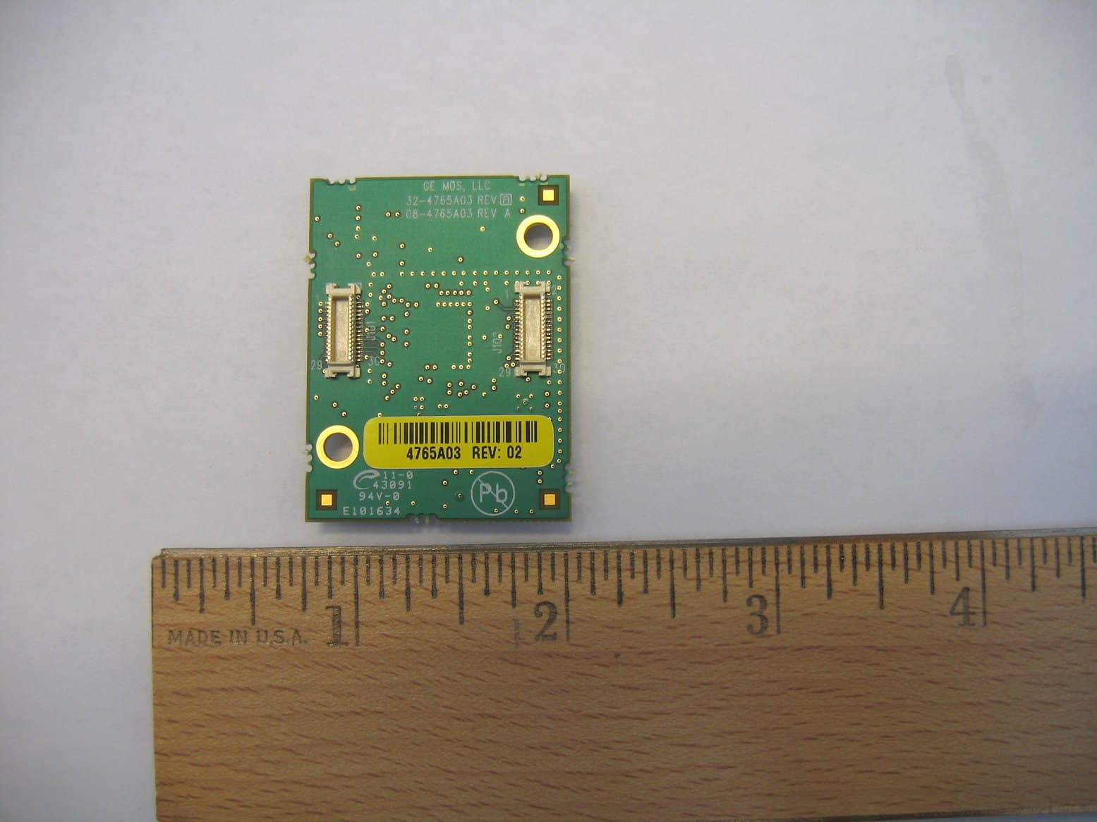
Click to zoom
Application Details
- Equipment Class
- DTS - Digital Transmission System
- Date of Grant
- Feb 17, 2010
- Application Purpose
- Original Equipment
- Date of Application
- Feb 15, 2010
- Equipment Note
- WiYZ Mesh Radio
- Frequency Range
- 2405.00000000 - 2475.00000000
- Company
- GE MDS, LLC
- Country
- United States
Documents & Files
Document Text
Text extracted from the exhibit documents filed with the FCC. Open a document above to read the original.
Users Manual
MESH2400MDS MESH2400 Radio Installation Guidelines1 of 1 MESH2400 Radio Installation Guidelines To comply with regulatory requirements products containing the GE MDS module shall: 1. In addition to any labeling requirements for the host system (such as those required by FCC Part 15 and ICES-003 for a digital device) the host device shall clearly display the FCC ID and Industry Canada number for the module on the outside of the device. W ording should be of the format: Contains FCC ID: E5MDS-MESH2400 Contains 101D-MESH2400 2. The module can only be used with the antennas associated with the device approvals. At this time those antennas are: Yagi: 97-4278A01 Omni: 97-4278A48 Panel: 97-4278A16 The system can only be operated with the antennas with which it was approved. Where the device has been subject to professional installation requirements the antenna may not be changed except by the professional installer. 3. The module can only be installed in host systems manufactured by GE MDS. The installation does not currently allow for collocating the device with other transm itters. 4. In addition to the relevant manual statements required by FCC Part 15 / ICES 003 for digital devices the host system manual must contain the following statement: Operation is subject to the following two conditions: (1) this device may not cause interference, and (2) this device m ust accept any interference, including interference that may cause undesired operation of the device. 5. The manual for the host system must also clearly explain the antenna installation requirements. The antenna installation requirements shall include the following statements: To comply with rf exposure requirements the antenna shall be installed to ensure a minimum separation distance of 20cm from persons. The antenna may not be collocated or operated in conjunction with other transmitting devices. To reduce potential radio interference to other users, the antenna type and its gain should be so chosen that the equivalent isotropically radiated power (e.i.r.p.) is not more than that permitted for successful communication. W here the host system uses standard rf connectors then professional installation for that system must be ensured in accordance with the policies already in place for similar part 15 systems. 6. The modular approval only covers the host system’s compliance with the technical requirements for the intentional radiator. Complete system verification against the digital device requirements of FCC Part 15, ICES 003 or other pertinent rules is required.
Users Manual
1.0INTRODUCTION 05-4953A01, Rev. 01GE MDS WiYZ Remote Quick Start Guide1 MDS WiYZ Remote Publication No. 05-4953A01, Rev. 01 The GE MDS WiYZ platform allows the connection of process sen- sors to a wireless network. Wirelessly networked sensors allow monitoring and control of equipment and processes without the infrastructure requirements of a hard-wired system. The WiYZ plat- form’s IP65 Outdoor Rating allows installation of the gateway and remotes outdoors, if required. In addition to these instructions, the MDS WiYZ System Reference Manual (05-4954A01) provides helpful guidance on WiYZ systems and menus. Also refer to the MDS WiYZ Gateway Quick Start Guide (05-4888A01). Electronic copies of all user documents and data sheets are available free of charge at www.GEmds.com. 1.1WiYZ Remote The WiYZ Remote is an industrial wireless solution for monitoring signals from directly connected sensors and other signaling devices. It provides robust, versatile communications even in harsh environments and at sites with limited power and communi- cation facilities. The unit’s self-contained design allows for quick installation and deployment without the nee d for additional accessories. The WiYZ Remote automatically determines communication routes with the WiYZ Gateway. Figure 1. WiYZ Remote 1.2Typical Application The WiYZ system allows the user to connect a network of sensors wirelessly, and to access collected sensor data through a variety of backhaul WAN interfaces. The WiYZ Remotes monitor analog signals from directly con- nected sensors and other signaling devices, such as warehouse video cameras, tank level sensors, and OEM instruments. 1.3Hardware Input/Output Configurations You can order the WiYZ Remote with four different hardware I/O configurations: 1.3.1 TRNR_PRD-72 This device supports a low voltage I/O set: • Two digital inputs (0 -5 VDC to 24 VDC) • Two digital outputs (2 A at 24 VDC) • Two analog voltage inputs (0-100 mV) • One 6 V (40 mA) sensor power supply output 1.3.2 TRNR_PRD-74 This device supports a high voltage I/O set: • Two digital inputs (0 -5 VDC to 24 VDC) • Two digital outputs (2 A at 24 VDC) • Two analog voltage inputs (0-5 V) • One 6 V (40 mA) sensor power supply output 1.3.3 TRNR_PRD-77 This device supports a current input I/O set: • Two digital inputs (0 -5 VDC to 24 VDC) • Two digital outputs (2 A at 24 VDC) • Two analog current inputs (0-22 mA) • One 24 V (40 mA) sensor power supply output 1.3.4 TRNR_PRD-78 This device supports a current output I/O set: • Two digital inputs (0 -5 VDC to 24 VDC) • Two digital outputs (2 A at 24 VDC) • Two analog current outputs (4-20 mA) • One 24 V (40 mA) sensor power supply output 2.0HARDWARE INSTALLATION Refer to Figure 2 on Page 3 for component locations. 2.1COM1 (J602) RS232 Diagnostic Pinouts RJ11 PinSignalDirection 4Transmit Data (TXD)Output 5Receive Data (RXD)Input 6Ground (GND)Input PRELIMINARY 2GE MDS WiYZ Remote Quick Start Guide05-4953A01, Rev. 01 2.2COM2 (J601) RS232/RS485 Payload Pinouts 2.3BATT (J208) Pinouts 2.4Terminal Strip (J201) Pinouts Footnotes: 1. All I/O has ESD protection. 2. Digital I/O is optically isolated fro m the sources with > 1500 V isola- tion. Digital Input – Accepts voltage input from either 5 VDC to 24 VDC, the digital inputs are interruptible, and these inputs can wake up the Remote. Digital Output – Can sink current 2 A @ 24 VDC, but cannot source any voltage. 2.4.1 Digital Input Pinouts 2.4.2 Digital Output Pinouts 2.4.3 Analog Input Pinouts 2.4.4 Analog Output Pinouts 2.4.5 Current Input Pinouts 2.4.6 Current Output Pinouts 2.5Additional Remote PCB Component Information Refer to Figure 2 on Page 3 for component locations. •On/Off switch (SW201) – Use this switch to enable/d isable power to the unit. Units with a battery ship from the factory with this switch in the OFF position. •Antenna mount (N-Connector) is certified for use with omni-directio nal antennas (up to 5 dBi gain) and Yagi anten- nas (up to 10 dBi gain). •Fuse (FH501) is a 2 A fuse. •LED Ribbon Cable Connector (J604) is under the battery bracket. •Status Switch (SW600) – Use this switch to wake the Remote, Activate the LEDs, and send a diagnostic message to the WiYZ Gateway. RJ45 PinSignalDirection 2Receive Data (RXD)Output 3Transmit Data (TXD)Input 5Ground (GND)Input 7Request to Send (RTS)Input 8Clear to Send (CTS)Output PinSignalDirection 1Vbatt+Output 2Vbatt-Input PinSignalDirection 1 Digital Input 1 (D_IN1) 1,2 Input 2 Digital Input 2 (D_IN2) 1,2 Input 3Digital Input CommonInput 4ISO Ground (Isolated GND)Input 5 Digital Output 1 (D_OUT1) 1,2 Output 6 Digital Output 2 (D_OUT2) 1,2 Output 7Digital Output Common (D_OUT_COMMON) 1,2 Output 8Ground (GND)Input 9Volt Input 1/Current Input 1+/Current Output 1+ 1 Refer to Section 2.4.1 through Section 2.4.6. Input/Output 10Volt Input 2/Current Input 1-/Current Output 1- 1 Refer to Section 2.4.1 through Section 2.4.6. Input/Output 11Ground (GND)Input 12Volt Output 1/Current Input 2+/Current Output 2+ 1 Refer to Section 2.4.1 through Section 2.4.6. Input/Output 13Volt Output 2/Current Input 2-/Current Output 2- 1 Refer to Section 2.4.1 through Section 2.4.6. Input/Output 14Power InInput 15Ground (GND)Input 16Sensor PowerOutput PinSignalDirection 1Digital Input 1Input 2Digital Input 2Input 3Isolated GroundInput PinSignalDirection 5Digital Output 1Output 6Digital Output 2Output 7Digital Output CommonOutput PinSignalDirection 9Voltage In 1Input 10Voltage In 2Input PinSignalDirection 12Voltage Out 1Output 13Voltage Out 2Output PinSignalDirection 9Current In 1+Input 10Current In 1-Input PinSignalDirection 9Current Out 1+Output 10Current Out 1-Output 05-4953A01, Rev. 01GE MDS WiYZ Remote Quick Start Guide3 2.6WiYZ Remote Installation Refer to Figure 3 during these steps, as required: 1. Attach the antenna. The antenna N-connector is certified for use with omni-directional antennas (up to 5 dBi gain) and Yagi antennas (up to 10 dBi gain). An appropriate Yagi antenna is the Maxrad MYP24010PT…
Text truncated - open the document above for the full version.
Cover Letter(s)
175 Science Parkway, Rochester, New York 14620 USA (585) 242-9600 Phone (585) 242-9620 Fax 1/8/10 FEDERAL COMMUNICATIONS COMMISSION 7435 Oakland Mills Road Columbia, MD 21046 U.S.A. Subject: Authority to Act as an Agent to FCC Applicant: GE MDS LLC. Product: MDS WiYZ Mesh radio FCC ID: E5MDS-MESH2400 Dear Sir/Madam, Elliott TCB 684 West Maude Ave. Sunnyvale, CA. 94085 This is your letter of authorization to accept our appointment of Elliott Laboratories, Inc. as our Agent for GE MDS LLC, to sign applications before Elliott TCB and to make representations to you on our behalf. Elliott Laboratories, Inc. is to receive and exchange data between our company and Elliott TCB. If you have any queries, please do not hesitate to contact me at 585 242-8440: Yours truly, Dennis McCarthy Agency Compliance Engineer GE Digital Energy -MDS 175 Science Parkway Rochester NY 14620 Phone (585) 242-8440 Email [email protected]
Cover Letter(s)
175 Science Parkway, Rochester, New York 14620 USA (585) 242-9600 Phone (585) 242-9620 Fax 1/11/10 FEDERAL COMMUNICATIONS COMMISSION 7435 Oakland Mills Road Columbia, MD 21046 U.S.A. Subject: Request for withholding from public disclosure the schematic diagrams and system block diagrams pursuant to an application for certification. Applicant: GE MDS LLC Product: Data Transceiver MDS MESH2400 Model: MDS MESH2400 FCC ID: E5MDS-MESH2400 Dear Sir/Madam, We, Microwave Data Systems, would like to request that the schematic diagrams, system block diagram and operational description submitted with the application for certification be withheld from public disclosure as per Section 0.459 of FCC Rules. This request is made under the provisions of Section 0.457(d) of the Commission's Rules, and Section 552(b)(4) of the Freedom of Information Act. These sections authorize as a withholding from public inspection materials which would be privileged as a matter of law if retained by the person submitting them, and materials which would not customarily be released to the public by that person. If you have any queries, please do not hesitate to contact me at 585 242-8440: Yours truly, Dennis McCarthy Agency Compliance Engineer GE Digital Energy -MDS 175 Science Parkway Rochester NY 14620 Phone (585) 242-8440 Email [email protected]
Cover Letter(s)
175 Science Parkway, Rochester, New York 14620 USA (585) 242-9600 Phone (585) 242-9620 Fax Jan 8th, 2010 Federal Communications Commission / Industry Canada / Elliott TCB Subject: Limited Modular approval Applicant: GE MDS LLC. Product: MDS WiYZ Mesh radio FCC ID: E5MDS-MESH2400 IC Number: 101D-MESH2400 Dear Sir/Madam, A Limited Modular Approval (LMA) is being requested for this device. There are eight requirements that the device must meet for full modular approval. According to the FCC’s definition of Limited Modular Approval: “If compliance with one or more of the numbered requirements, listed above, cannot be demonstrated, it may be possible to obtain a "Limited Modular Approval" (LMA). This will be issued in those instances where the Grantee can demonstrate that it will retain control over the final installation of the device, such that compliance of the end product is assured. In such a case, an operating condition on the grant of equipment authorization for the module would state that the module is only approved for use when installed in devices produced by a specific manufacturer, typically the Grantee. If LMA is sought, the application for equipment authorization must make this fact clear. It must also specifically state how control of the end product, into which the module will be installed, will be maintained, such that full compliance of the end product is always ensured. “ We are requesting LMA, Limited Modular Approval. The following pages detail how the module meets the requirements for modular approval and the limitations related to the antenna installation that require a limited modular approval, restricting use of the module only to those host systems manufactured by GE MDS. 1. The module must have its own RF shielding. The module has its own RF shielding. The bottom layer of the circuit board is a contiguous ground plane and the top side of the board has a metal shield that connects into the ground plane covering the rf section, with the exception of the rf coaxial connector. The external photographs clearly show the shielding on the top side of the board and ground plane on the bottom side. 2. All modulation and data input(s) are buffered. The Freescale MC1322x Platform in a Package (PiP) performs data buffering – refer to the block diagram for more details. 3. The module has its own power supply regulation and local reference oscillator. The module contains its own power supply regulation and the rf reference oscillator is contained within the module Y101 and U101. Power supply regulation is provided U202 . 4. The modular transmitter must comply with the antenna requirements of Section 15.203 and 15.204(c). The certification submission contains a detailed description of the configuration of all antennas that will be used with the module. Testing was performed to cover three different antenna types by performing radiated measurements with the highest gain antennas of each type. In addition, output power measurements were made for each antenna type as the output power settings are different for each antenna type. Datasheets for the antennas are provided with this application. The module uses a uFL connector to connect to the antenna. This is a non-standard antenna type. However, we intend to use this module in host systems that could use standard rf connectors and we fully understand the requirements for professional installation of such host systems. For this reason we are requesting a limited modular approval, with approval limited to installation of this module into host systems by the Grantee. GEMDS will perform training for its staff to inform them of the scope of the Limited Modular Approval and list the technical requirements to ensure its staff keeps the installations in compliance. None of the GEMDS’ products that incorporate this module will be for sale to the general public as the complete line of GEMDS products are for Industrial applications only. Examples of such applications include SCADA applications, traffic control, flow rate applications. GEMDS has a trained staff of technical personnel that work with our industrial customers to ensure that professional installation is achieved for all unlicensed products that operate with standard rf connectors and/or utilize different power settings for different antenna installations. In all cases the FCC EIRP limits are maintained and power settings are configured to ensure EMC requirements are met. 5. The modular transmitter must be tested in a stand-alone configuration, i.e., the module must not be inside another device during testing. This is intended to demonstrate that the module is capable of complying with Part 15 emission limits regardless of the device into which it is eventually installed. Unless the transmitter module will be battery powered, it must comply with the AC line conducted requirements found in Section 15.207. Test data contained in this application is for the device tested as a stand-alone device. Radiated spurious emissions data and AC conducted emissions data demonstrating compliance with the requirements of Part 15 of the FCC rules for intentional radiators has been provided. 6. [FCC only] The modular transmitter must be labeled with its own FCC ID number, and, if the FCC ID is not visible when the module is installed inside another device, then the outside of the device into which the module is installed must also display a label referring to the enclosed module. This exterior label can use wording such as the following: “Contains Transmitter Module FCC ID: XYZMODEL1” or “Contains FCC ID: XYZMODEL1.” The module is appropriately labeled (refer to the label and label location drawings contained within this application). GEMDS are limiting the use of this module to installation into their systems and fully understand the requirements for labeling the outside of host systems with the appropriate verbiage to indicate the FCC ID of the module. 7. The modular transmitter must comply with any s…
Text truncated - open the document above for the full version.
ID Label/Location Info
Label and Label Location Label with model number and certification number is located on top of the shield. The brand name is contained on the silkscreen for the PCB on the rear side – see below.
ID Label/Location Info
PRODUCT USE:All statements, technical information and recommendations contained in this document are based upon tests or experience that 3M believes are reliable. However, many factors beyond 3M’s control can affect the use and performance of a 3M product in a particular application, including the conditions under which the product is used and the time and environmental conditions in which the product is expected to perform. Since these factors are uniquely within the user’s knowledge and control, it is essential that the user evaluate the 3M product to determine whether it is fit for a particular purpose and suitable for the user’s method of application.WARRANTY AND LIMITED REMEDY: Unless stated otherwise in 3M’s product literature, packaging inserts or product packaging for individual products, 3M warrants that each 3M product meets the applicable specifications at the time 3M ships the product. Individual products may have additional or different warranties as stated on product literature, package inserts or product packages. 3M MAKES NO OTHER WARRANTIES, EXPRESS OR IMPLIED, INCLUDING, BUT NOT LIMITED TO, ANY IMPLIED WARRANTY OF MERCHANTABILITY OR FITNESS FOR A PARTICULAR PURPOSE OR ANY IMPLIED WARRANTY ARISING OUT OF A COURSE OF DEALING, CUSTOM OR USAGE OF TRADE.User is responsible for determining whether the 3M product is fit for a particular purpose and suitablefor user’s application. If the 3M product is defective within the warranty period, your exclusive remedy and 3M’s and seller’s sole obligation will be, at 3M’s option, to repair or replace the product or refund the purchase price.LIMITATION OF LIABILITY: Except where prohibited by law, 3M and seller will not be liable for any loss or damage arising from the 3M product, whether direct, indirect, special, incidental or consequential, regardless of the legal theory asserted, including warranty, contract, negligence or strict liability. 3M is a trademark of 3M Printed in U.S.A. © 3M 2005 60-5002-0089-8 Electronics Building 21-W-10 900 Bush Avenue St. Paul, MN 55106 800-422-8116 • 877-722-5072 (fax) www.3m.com/electronics Applications and general properties of 3M ™ Performance Label Materials ApplicationUnique Application NeedsProduct Family/DescriptionProduct Mil Thickness Color Choices (Face/Adhesive only) If you need additional information, please contact Performance Label Materials: 1-800-422-8116 or www.3M/converter 1. Identifying/Informing/Warning Certification, Instruction, Thermal transfer printable with adhesion toThermal Transfer Polyester with 350 High Holding Adhesive78713.8Gloss white or Warning Label difficult surfaces for life of the product78683.1Gloss white 78723.8Matte platinum Thermal Transfer Polyester with P1650 High Performance AdhesiveFM0332023.3Gloss white FM0322024.5Bright silver Identification Cost effective thermal transfer printableThermal Transfer Polyester with 310 High Precision Adhesive78153.1Matte white and Information Labelwith adhesion to many surfaces for 78162.8Gloss white life of the product78184.1Matte silver 78752.8Platinum Low cost, general purpose thermal transfer label materialThermal Transfer Polyester with P1400 High Performance AdhesiveOFM034022.9Gloss white with adhesion to many surfaces for ife of the product.OFM035022.9Matte white Recyclable LabelLabel stock is recycling compatible with PC, ABS, PS, Recycling Compatible ABS with 350 High Holding Adhesive80004.2Matte white HIPS & PC/ABS plastics. Thermal Transfer Printable. Re-work LabelPermanent yet cleanly removable on manyThermal Transfer Polyester with 550 Removable Adhesive57702.8Matte white substrates. Low-outgassing adhesive resists 57713.1Gloss white flagging and edge lifting on disk drive applications. 2. Tracking Inventory Control LabelCost effective thermal transfer printableThermal Transfer Polyester with 310 High Precision Adhesive78153.1Matte white with adhesion to many surfaces for life 78162.8Gloss white of product78752.8Platinum Low cost, general purpose thermal transfer Thermal Transfer Polyester with P1400 High Performance AdhesiveOFM034022.9Gloss white label material with adhesion to many OFM24022.9Matte silver surfaces for life of the product PCB Tracking LabelBarcode printable with high temperatureHigh Temperature Polyimide (Kapton™) with 100 High Temp Adhesive78114.0Matte white resistance. Survives solder processing.78124.0Matte white High temperature resistance. High Temperature Acrylate with 150 High Temp Adhesive39232.8Matte white Thermal transfer printable. Laser Markable Label MaterialLaser etchable film, most durable Laser Etch Acrylate with 350 High Holding Adhesive7847 3.6 Matte black on white label construction.78483.6 Matte silver on black 3. Securing Tamper Indicating LabelTamper indicating stocks designed to provide VOID Tamper Indicating Polyester with 350 High Holding Adhesive7381/7866 3.0Gloss white a “void” message in the facestock when 73803.0Bright silver removal is attemptedVOID Tamper Indicating Polyester with P1410 Tackified AdhesiveFMV22 2.9Gloss white FMV022.9Bright silver Tamper indicating material designed to provideTriangle Tamper Indicating Polyester with P1410 Tackified AdhesiveFMV01202 2.9Bright silver triangle pattern when removal is attemptedFMV014022.9Gloss white Tamper evident material destructs if attempts Destructible Vinyl with 350 High Holding Adhesive7613 2.8 Matte white are made to remove from substrateDestructible Vinyl with 200 High Strength Adhesive78853.0Matte white 4. Protecting MaskingUltra clear, printable label material for lens Highly Transparent Polyester with Removable Adhesive769912.0Ultra clear protection applications. Low tack adhesive with clean removability. High tack adhesive with ultra clean removal.Thermal Transfer Polyester with R3500 Ultra Removable AdhesiveFM1542 2.8Gloss clear Press Printable Polypropylene with R3500 Ultra Removable Adhesive FP562 2.8Clear OverlaminateProtects surface of label from abrasion, sunlight,Non-topcoated Polyester with P14…
Text truncated - open the document above for the full version.
RF Exposure Info
MPE Calculations The device is not a portable device (i.e. intended to be worn on the body or be hand- held), so it is classified as being either a mobile device or a fixed mounted device. The documentation associated with the filing for device authorization specifies a minimum separation distance of at least 20cm, consistent with this classification. FCC part 1.1310, Table 1 limits the power density for uncontrolled exposure. The power density, P d (mW/cm 2 ) calculated from the maximum EIRP, P t (mW) and the distance, d (m), between the transmitting antenna and the closest person, can be calculated using: P d = P t /(4 πd 2 ) Frequency MPE Limit (mW/cm 2 ) Output Power (mW) Max. Antenna Gain (dBi) EIRP (mW) Pd at 20cm (mW/cm 2 ) Distance where Pd = limit (cm) 2405 to 2475 MHz 1.00 23.4 2.0 Omni 37.2 0.007 1.7 2405 to 2475 MHz 1.00 0.8 10.0 Yagi 8.3 0.002 0.8 2405 to 2475 MHz 1.00 1.5 12.0 Panel 24.0 0.005 1.4 As shown in the calculations above, the power density 20cm from the device is below the maximum permitted level for uncontrolled exposure. It should also be noted that the output power from the device is a maximum of 23.4mW. This power level is below the FCC’s threshold of 60/f (24.2mW at 2475 MHz) and therefore the device is below the lower threshold that would require rf exposure evaluation for portable or mobile exposure conditions. The power level is not below the RSS-102 eirp threshold of 20mW.
Test Report
File: R77902 Page 1 of 24 EMC Test Report Application for Grant of Equipment Authorization pursuant to Industry Canada RSS-Gen Issue 2 / RSS 210 Issue 7 FCC Part 15 Subpart C Model: WiYZ Mesh Radio IC CERTIFICATION #: 101D-MESH2400 FCC ID: E5MDS-MESH2400 APPLICANT: GE MDS LLC 175 Science Parkway Rochester, NY 14620 TEST SITE(S): Elliott Laboratories 684 W. Maude Avenue Sunnyvale, CA 94085 IC SITE REGISTRATION #: 2845A-1; 2845A-2 REPORT DATE: February 4, 2010 FINAL TEST DATES: November 25, 30, December 21, 29 2009 and January 4, 5 2010 AUTHORIZED SIGNATORY: ______________________________ Mark Briggs Staff Engineer Elliott Laboratories Elliott Laboratories is accredited by the A2LA, certificate number 2016.01, to perform the test(s) listed in this report, except where noted otherwise. This report shall not be reproduced, except in its entirety, without the written approval of Elliott Laboratories Testing Cert #2016.01 Elliott Laboratories -- EMC Department Test Report Report Date: February 4, 2010 File: R77902 Page 2 of 24 REVISION HISTORY Rev# Date Comments Modified By - February 4, 2010 First release Elliott Laboratories -- EMC Department Test Report Report Date: February 4, 2010 File: R77902 Page 3 of 24 TABLE OF CONTENTS REVISION HISTORY .............................................................................................................................................. 2 TABLE OF CONTENTS .......................................................................................................................................... 3 SCOPE........................................................................................................................................................................ 5 OBJECTIVE .............................................................................................................................................................. 5 STATEMENT OF COMPLIANCE......................................................................................................................... 6 DEVIATIONS FROM THE STANDARDS ............................................................................................................ 6 TEST RESULTS SUMMARY ................................................................................................................................. 7 DIGITAL TRANSMISSION SYSTEMS (2400 – 2483.5MHZ) ............................................................................ 7 GENERAL REQUIREMENTS APPLICABLE TO ALL BANDS........................................................................ 7 MEASUREMENT UNCERTAINTIES..................................................................................................................8 EQUIPMENT UNDER TEST (EUT) DETAILS .................................................................................................... 9 GENERAL.............................................................................................................................................................. 9 OTHER EUT DETAILS......................................................................................................................................... 9 ANTENNA SYSTEM ............................................................................................................................................ 9 ENCLOSURE......................................................................................................................................................... 9 MODIFICATIONS................................................................................................................................................. 9 SUPPORT EQUIPMENT....................................................................................................................................... 9 EUT INTERFACE PORTS .................................................................................................................................. 10 EUT OPERATION ............................................................................................................................................... 10 TEST SITE............................................................................................................................................................... 11 GENERAL INFORMATION ............................................................................................................................... 11 CONDUCTED EMISSIONS CONSIDERATIONS ............................................................................................ 11 RADIATED EMISSIONS CONSIDERATIONS ................................................................................................ 11 MEASUREMENT INSTRUMENTATION .......................................................................................................... 12 RECEIVER SYSTEM .......................................................................................................................................... 12 INSTRUMENT CONTROL COMPUTER .......................................................................................................... 12 LINE IMPEDANCE STABILIZATION NETWORK (LISN)............................................................................. 12 FILTERS/ATTENUATORS ................................................................................................................................ 13 ANTENNAS......................................................................................…
Text truncated - open the document above for the full version.
Contact Information
Applicant
John Barenys(Senior Operations Manager)
Technical Contact
Test Firm
NTS Labs, LLC Fremont & NewarkDavid Bare
Technical Specifications
| # | Rule Parts | Frequency Range | Power Output |
|---|---|---|---|
| 1 | 15C | 2.40 GHz - 2.48 GHz | 23.40 mW |
Other Applications from GE MDS, LLC

E5MDS-NET9S
Jul 13, 2023Frequency Hopping Radio
Equipment Class
DSS - Part 15 Spread Spectrum Transmitter
E5MDS-NET9L
Jul 11, 2023Frequency Hopping Radio
Equipment Class
DSS - Part 15 Spread Spectrum Transmitter
E5MDS-LN900
Jan 27, 2016Industrial Radio Module
Equipment Class
TNB - Licensed Non-Broadcast Station Transmitter
E5MDS-SDM4
Aug 20, 2015MDS SDM4 Licensed Spectrum Module
Equipment Class
TNB - Licensed Non-Broadcast Station Transmitter
E5MDS-LN400
Jul 09, 2015Industrial Radio Module
Equipment Class
TNB - Licensed Non-Broadcast Station Transmitter