E5MDS-ROR220MDS ROR220 DATA TRANSCEIVER
GE MDS, LLC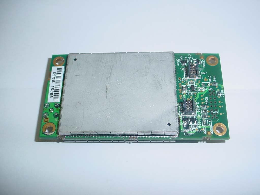
Click to zoom
Application Details
- Equipment Class
- TNB - Licensed Non-Broadcast Station Transmitter
- Date of Grant
- Mar 04, 2004
- Application Purpose
- Original Equipment
- Date of Application
- Mar 04, 2004
- Equipment Note
- MDS ROR220 DATA TRANSCEIVER
- Frequency Range
- 217.00000000 - 222.00000000
- Company
- GE MDS, LLC
- Country
- United States
Documents & Files
Document Text
Text extracted from the exhibit documents filed with the FCC. Open a document above to read the original.
Users Manual
Integration Guide 217-222 MHz Licensed OEM Transceiver ROR Module Microwave Data Systems Inc. MDS 05-4132A01, Rev. A MARCH 2004 (PRELIMINARY) MDS 05-4132A01, Rev. AROR Transceiver Moduleiii TABLE OF CONTENTS 1.0 INTRODUCTION ......................................................................... 7 1.1 Modem Speed versus Channel Bandwidth ...................................... 7 1.2 Frequency Coverage ........................................................................ 7 2.0 INSTALLATION DESIGN ............................................................. 8 2.1 Antennas and Feedlines .................................................................. 9 Antennas ............................................................................................ 9 Feedlines .......................................................................................... 10 2.2 Primary Power (6-12 Vdc) .............................................................. 10 DC Supply Connection ..................................................................... 10 Sleep Mode (Energy Conservation) ................................................. 10 Shutdown Mode (Power Supply Disabled) ....................................... 11 2.3 Detailed Pin Descriptions ............................................................... 11 2.4 Transceiver Configuration and Diagnostic Commands .................. 12 2.5 In-Service Operation—Radio & Data Configuration ....................... 14 2.6 Using the Evaluation Board (P/N 03-4051A01) .............................. 15 Connecting the Evaluation Board & Transceiver............................... 16 2.7 Cable Connections for Benchtop Testing ....................................... 17 Antenna Connection (J300 on the ROR module) ............................. 18 Diagnostic Connection (J4) .............................................................. 18 Data Connector (J5) ......................................................................... 19 DC Power Connector (J3)................................................................. 20 Jumper Block J1 (DC Power Configuration) ..................................... 21 2.8 Benchtop Power-Up & Configuration ............................................. 21 3.0 TECHNICAL REFERENCE ....................................................... 22 3.1 Transceiver Specifications .............................................................. 22 3.2 dBm-Watts-Volts Conversion Chart ................................................ 24 4.0 GLOSSARY OF TERMS............................................................ 25 Copyright Notice This Installation and Operation Guide and all software described herein are copyright: 2004 Microwave Data Systems Inc . All rights reserved. Microwave Data Systems Inc. reserves its right to correct any errors and omissions in this publication. ivROR Transceiver ModuleMDS 05-4132A01, Rev. A Antenna Installation Warnings 1. All antenna installation and servicing is to be performed by qualified technical personnel only. When servicing the antenna, or working at distances closer than those listed below, ensure the transmitter has been disabled. 2. Depending upon the application and the gain of the antenna, the total composite power could exceed 90 watts EIRP. For fixed/mobile configuration, the distances in the table below must be followed. Requirements for Portable Applications For portable applications with a directly connected antenna, the device and its maximum gain antenna of 2.1 dBi must operate with a separation distance of at least 2.5 cm from all persons and must not be co-located or operating in conjunction with any other antenna or transmitter. The device must transmit with a source-based, time averaging duty factor not exceeding 2.6%. End users of this product must be provided with specific instructions for satisfying RF exposure compliance require- ments. When the ROR 220 module is to be used in portable applications, it must be re-tested by the integrator and carry its own FCC identifi- cation number. ISO 9001 Registration Microwave Data Systems adheres to this internationally accepted quality system standard. MDS Quality Policy Statement We, the employees of Microwave Data Systems Inc., are committed to understanding and exceeding our customer’s needs and expectations. • We appreciate our customer’s patronage. They are our business. • We promise to serve them and anticipate their needs. • We are committed to providing solutions that are cost effective, innovative and reliable, with consistently high levels of quality. • We are committed to the continuous improvement of all of our systems and processes, to improve product quality and increase customer satisfaction. RF Exposure Separation distances required for FCC RF Exposure compliance Antenna Gain vs. Minimum Safety Distance (Based on a 100% Duty Cycle, 0 dB Feedline Loss) Fixed/Mobile Antenna Gain 0–5 dBi5–10 dBi10–16.5 dBi Minimum RF Safety Distance 0.58 meter1.04 meters2.19 meters MDS 05-4132A01, Rev. AROR Transceiver Modulev ESD Notice To prevent malfunction or damage to this product, which may be caused by Electrostatic Discharge (ESD), the radio should be properly grounded at the time of installation. In addition, the installer or main- tainer should follow proper ESD precautions, such as touching a bare metal object to dissipate body charge, prior to touching components or connecting/disconnecting cables. Manual Revision and Accuracy While every reasonable effort has been made to ensure the accuracy of this manual, product improvements may result in minor differences between the manual and the product shipped to you. If you have addi- tional questions or need an exact specification for a product, please con- tact our Customer Service Team using the information at the back of this guide. In addition, manual updates can often be found on the MDS Web site at www.microwavedata.com. FCC Modular Approval Notice (Pending) This device is offered as…
Text truncated - open the document above for the full version.
Attestation Statements
175 Science Parkway, Rochester, New York 14620 USA (585) 242-9600 Phone (585) 242-9620 Fax Feb 26, 2004 FEDERAL COMMUNICATIONS COMMISSION 7435 Oakland Mills Road Columbia, MD 21046 USA Subject: Part 90.203(e) Compliance Attestation Applicant: Microwave Data Systems Inc. Product: MDS ROR 220 Data Transceiver Model: MDS-ROR220 FCC ID: E5MDS-ROR220 Dear Sir or Madam: This equipment meets the requirements of the FCC Rules, Parts 90.203(e) except as provided in paragraph (g) of the section 203. The operator cannot program and transmit on frequencies other than those programmed by the manufacturer, service or maintenance personnel, using the equipment’s external operational controls. Yours sincerely Dennis McCarthy Agency Compliance Engineer Microwave Data Systems 175 Science Parkway Rochester NY 14620 Phone (585) 242-8440 Email [email protected]
Cover Letter(s)
175 Science Parkway, Rochester, New York 14620 USA (585) 242-9600 Phone (585) 242-9620 Fax January 22, 2004 FEDERAL COMMUNICATIONS COMMISSION 7435 Oakland Mills Road Columbia, MD 21046 U.S.A. Subject: Request for withholding from public disclosure the schematic diagrams and system block diagrams pursuant to an application for certification. Applicant: Microwave Data Systems Inc. Product: MDS ROR 220 Data Transceiver Model: MDS-ROR220 FCC ID: E5MDS-ROR220 Dear Sir/Madam, We, Microwave Data Systems Inc., would like to request that the schematic diagrams, system block diagram, Theory of Operation and Bill of Materials submitted with the application for certification be withheld from public disclosure as per Section 0.459 of FCC Rules. This request is made under the provisions of Section 0.457(d) of the Commission's Rules, and Section 552(b)(4) of the Freedom of Information Act. These sections authorize as a withholding from public inspection materials which would be privileged as a matter of law if retained by the person submitting them, and materials which would not customarily be released to the public by that person. If you have any queries, please do not hesitate to contact me at 585 242-8440: Yours truly, Dennis McCarthy Agency Compliance Engineer Microwave Data Systems 175 Science Parkway Rochester NY 14620 Phone (585) 242-8440 Email [email protected]
Cover Letter(s)
175 Science Parkway, Rochester, New York 14620 USA (585) 242-9600 Phone (585) 242-9620 Fax February 27, 2004 FEDERAL COMMUNICATIONS COMMISSION 7435 Oakland Mills Road Columbia, MD 21046 U.S.A. Applicant: Microwave Data Systems Inc. Product: MDS ROR 220 Data Transceiver Model: MDS-ROR220 FCC ID: E5MDS-ROR220 Subject: “Modular Approval” request for new 220MHz transceiver design, proposed FCC identifier E5MDS-ROR220 Dear Sir/Madam, Microwave Data Systems is requesting that FCC ID E5MDS-ROR220 is granted Modular Approval. This design is NOT an FCC part 15.247 unlicensed device, but rather a licensed FCC part 90 device. None of MDS’s products are for sale to the general public, and are for Industrial applications only, examples, SCADA applications, traffic control, flow rate applications. Thus MDS has a trained staff of technical personnel that work with our industrial customers to ensure “professional installation” is achieved. When Modular approval is granted, MDS will perform training on it’s staff, inform them of the “Modular Approval” requirements. The antenna and cable interfaces, are a NON standard “MCX” connectors, and the cable interconnects do fulfill the FCC’s Modular requirements. All the antennas that will be used with the grant, will be installed by trained/qualified personnel to ensure the strictest compliance with FCC rules. All supporting manuals and sales literature reflect the regulatory issues. The following text will be placed in the ROR220 installation and user manual, and is being “requested” on the FCC grant. "This device is only approved for use when installed in devices approved by third-party OEMs, or produced by the Grantee. The antenna(s) to be used with this modular transmitter must be installed to provide a separation distance of at least .58 meters from all persons and must not be co-located or operating in conjunction with any other antenna or transmitter. End-users and installers must be provided with antenna installation and transmitter operating conditions for satisfying RF exposure compliance. Professional installation of this product is required." Per the FCC rules, here are our requirements and our compliance Several factors should be considered when seeking an equipment authorization for modular transmitters: (a) In order to be considered a transmitter module, the device must be a complete RF transmitter, i.e., it must have its own reference oscillator (e.g., VCO), antenna, etc. The only connectors to the module, if any, may be power supply and modulation/data inputs. MDS COMPLIES and meets these requirements (b) Compliance with FCC RF Exposure requirements may, in some instances, limit the output power of a module and/or the final applications in which the approved module may be employed. Not applicable to this design (c) While the applicant for a device into which an authorized module is installed is not required to obtain a new authorization for the module, this does not preclude the possibility that some other form of authorization or testing may be required for the device (e.g., a WLAN into which an authorized module is installed must still be authorized as a PC peripheral, subject to the appropriate equipment authorization). The enclosures it is intended to be installed will have FCC part 15 unintentional radiator testing prior to shipment (d) In the case of a modular transceiver, the modular approval policy only applies to the transmitter portion of such devices. Pursuant to Section 15.101(b), the receiver portion will either be subject to Verification, or it will not be subject to any authorization requirements (unless it is a Scanning Receiver, in which case it is also subject to Certification, pursuant to Section 15.101(a)). The enclosures it is intended to be installed will have FCC part 15 unintentional radiator testing prior to shipment (e) The holder of the grant of equipment authorization (Grantee) of the module is responsible for the compliance of the module in its final configuration, provided that the OEM, integrator, and/or end user has complied with all of the instructions provided by the Grantee which indicate installation and/or operating conditions necessary for compliance. MDS is aware of this and will comply with the enclosures In order to obtain a modular transmitter approval, a cover letter requesting modular approval must be submitted and the numbered requirements identified below must be addressed in the application for equipment authorization. 1. The modular transmitter must have its own RF shielding. This is intended to ensure that the module does not have to rely upon the shielding provided by the device into which it is installed in order for all modular transmitter emissions to comply with Part 15 limits. It is also intended to prevent coupling between the RF circuitry of the module and any wires or circuits in the device into which the module is installed. Such coupling may result in non- compliant operation. MDS COMPLIES and it passed the FCC testing 2. The modular transmitter must have buffered modulation/data inputs (if such inputs are provided) to ensure that the module will comply with Part 15 requirements under conditions of excessive data rates or over-modulation. MDS COMPLIES, the microprocessor data buffers 3. The modular transmitter must have its own power supply regulation. This is intended to ensure that the module will comply with Part 15 requirements regardless of the design of the power supplying circuitry in the device into which the module is installed. MDS COMPLIES, DC switching regulator on board 4. The modular transmitter must comply with the antenna requirements of Section 15.203 and 15.204(c). The antenna must either be permanently attached or employ a “unique” antenna coupler (at all connections between the module and the antenna, including the cable). Any antenna used with the module must be approved with the module, either at the time of initial authorization or through a Class II permissive ch…
Text truncated - open the document above for the full version.
External Photos
ANNEX 2 – EXTERNAL EUT PHOTOS Microwave Data Systems Inc. MDS ROR220 Data Transceiver, Model MDS-ROR220 FCC ID: E5MDS-ROR220 IC: 3738A-ROR220 A2 - 1 ANNEX 2 – EXTERNAL EUT PHOTOS Microwave Data Systems Inc. MDS ROR220 Data Transceiver, Model MDS-ROR220 FCC ID: E5MDS-ROR220 IC: 3738A-ROR220 A2 - 2
ID Label/Location Info
MDS 05-4132A01, Rev. AROR Transceiver Modulev Manual Revision and Accuracy While every reasonable effort has been made to ensure the accuracy of this manual, product improvements may result in minor differences between the manual and the product shipped to you. If you have addi- tional questions or need an exact specification for a product, please con- tact our Customer Service Team using the information at the back of this guide. In addition, manual updates can often be found on the MDS Web site at www.microwavedata.com. FCC Modular Approval Notice (Pending) This device is offered as a Modular Transmitter in per FCC Part 90. It is approved for use under the following conditions: (1) When this device is placed inside an enclosure, a durable label must be affixed to the out- side of that enclosure indicating the unit’s FCC ID Number: E5MDS-ROR220. (2) Changes or modifications not expressly approved by the party responsible for compliance could void the user’s authority to operate the equipment. FCC Part 15 Notice (Pending) This equipment has been tested and found to comply with the limits for a Class B digital device, pursuant to Part 15 of the FCC Rules. These limits are designed to provide reasonable protection against harmful interference in a residential installation. This equipment generates, uses, and can radiate radio frequency energy and, if not installed and used in accordance with the instructions, may cause harmful interference to radio communications. However, there is no guarantee that interference will not occur in a particular installation. If this equipment does cause harmful interference to radio or television reception, which can be deter- mined by turning the equipment off and on, the user is encouraged to try and correct the interference by one or more of the following measures: • Reorient or locate the receiving antenna. • Increase the separation between the equipment and receiver. • Connect the equipment into an outlet on a circuit different from that to which the receiver is connected. • Consult the dealer or an experienced radio/TV technician for help. Industry Canada RSS-119 (Pending) This Class B digital apparatus complies with Canadian RSS-119. Cet appareil numérique de la classe B est conforme à la norme RSS-119 du Canada.
Internal Photos
ANNEX 3 – INTERNAL EUT PHOTOS Microwave Data Systems Inc. MDS ROR 220 Data Transceiver, Model MDS-ROR220 FCC ID: E5MDS-ROR220 IC: 3738A-ROR220 A3 - 1 ANNEX 3 – INTERNAL EUT PHOTOS Microwave Data Systems Inc. MDS ROR 220 Data Transceiver, Model MDS-ROR220 FCC ID: E5MDS-ROR220 IC: 3738A-ROR220 A3 - 2 ANNEX 3 – INTERNAL EUT PHOTOS Microwave Data Systems Inc. MDS ROR 220 Data Transceiver, Model MDS-ROR220 FCC ID: E5MDS-ROR220 IC: 3738A-ROR220 A3 - 3
Parts List/Tune Up Info
175 Science Parkway, Rochester, New York 14620 USA (585) 242-9600 Phone (585) 242-9620 Fax February 27, 2004 FEDERAL COMMUNICATIONS COMMISSION 7435 Oakland Mills Road Columbia, MD 21046 U.S.A. Subject: Radio tune up procedures and duty cycle information Applicant: Microwave Data Systems Inc. Product: MDS ROR 220 Data Transceiver Model: MDS-ROR220 FCC ID: E5MDS-ROR220 We, Microwave Data Systems Inc., would like to submit the below information pertaining to the Radio tune up and duty cycle with our grant application. Tune up Procedure: This radio is controlled by a A to D converter and microporcessor. All the calibration is done in the factory and the only user adjustable part is the Receiver front end Helical filter. There are no transmitter adjustable parts to the end user, if a tune up is required the unit must be returned to the factory to be recalibrated on an automatic software controlled test bench. Duty Cycle: Duty cycle was derived from the fact that there are 45 possible transmitter time slots per second. For standard operation only 1 of the 45 time slots will be used by a remote (OCU) that corresponds to a duty cycle of 2.2%. Theoretical worst case “special diagnostic operation” would be 15 of the 45 time slots which is 33% If you have any queries, please do not hesitate to contact me at 585 242-8440: Yours truly, Dennis McCarthy Agency Compliance Engineer Microwave Data Systems 175 Science Parkway Rochester NY 14620 Phone (585) 242-8440 Email [email protected]
Test Report
MDS ROR220 Data Transceiver Model No.: MDS-ROR220 FCC ID: E5MDS-ROR220 Applicant: Microwave Data Systems 175 Science Parkway Rochester, NY USA, 14620-4261 Tested in Accordance With Federal Communications Commission (FCC) 47 CFR, Parts 2 and 90 (Subparts I, T & K) UltraTech's File No.: MIC-109FCC90 This Test report is Issued under the Authority of Tri M. Luu, Professional Engineer, Vice President of Engineering UltraTech Group of Labs Date: March 9, 2004 Report Prepared by: Anca Dobre Issued Date: March 9, 2004 Tested by: Mr. Wayne Wu Test Dates: February 3 - 19, 2004 The results in this Test Report apply only to the sample(s) tested, and the sample tested is randomly selected. This report must not be used by the client to claim product endorsement by NVLAP or any agency of the US Government. UltraTech 3000 Bristol Circle, Oakville, Ontario, Canada, L6H 6G4 Tel.: (905) 829-1570 Fax.: (905) 829-8050 Website: www.ultratech-labs.com , Email: [email protected], Email: [email protected] 2 31040/SIT C-1376 46390-2049 200093-0 SL2-IN-E-1119R 00-034 FCC PARTS 2 and 90, SUBPARTS I, T & K, NON-BROADCAST RADIO TRANSCEIVERS Contents i MDS ROR220 Data Transceiver, Model MDS-ROR220 FCC ID: E5MDS-ROR220 ULTRATECH GROUP OF LABS Ultratech File #: MIC-109FCC90 3000 Bristol Circle, Oakville, Ontario, Canada L6H 6G4 March 9, 2004 Tel. #: 905-829-1570, Fax. #: 905-829-8050, Email: [email protected] , Website: http://www.ultratech-labs.com All test results contained in this engineering test report are traceable to National Institute of Standards and Technology (NIST) TABLE OF CONTENTS EXHIBIT 1. SUBMITTAL CHECK LIST ........................................................................................................................................ 1 EXHIBIT 2. INTRODUCTION .......................................................................................................................................................... 2 2.1. SCOPE .......................................................................................................................................................................................... 2 2.2. RELATED SUBMITTAL(S)/GRANT(S)..................................................................................................................................... 2 2.3. NORMATIVE REFERENCES ..................................................................................................................................................... 2 EXHIBIT 3. PERFORMANCE ASSESSMENT ............................................................................................................................... 3 3.1. CLIENT INFORMATION ............................................................................................................................................................ 3 3.2. EQUIPMENT UNDER TEST (EUT) INFORMATION............................................................................................................... 3 3.3. EUT’S TECHNICAL SPECIFICATIONS.................................................................................................................................... 4 3.4. LIST OF EUT’S PORTS............................................................................................................................................................... 5 3.5. ANCILLARY EQUIPMENT ........................................................................................................................................................ 5 EXHIBIT 4. EUT OPERATING CONDITIONS AND CONFIGURATIONS DURING TESTS................................................. 6 4.1. CLIMATE TEST CONDITIONS ................................................................................................................................................. 6 4.2. OPERATIONAL TEST CONDITIONS & ARRANGEMENT FOR TEST SIGNALS............................................................... 6 EXHIBIT 5. SUMMARY OF TEST RESULTS................................................................................................................................ 7 5.1. LOCATION OF TESTS................................................................................................................................................................ 7 5.2. APPLICABILITY & SUMMARY OF EMISSION TEST RESULTS.......................................................................................... 7 5.3. MODIFICATIONS INCORPORATED IN THE EUT FOR COMPLIANCE PURPOSES.......................................................... 7 5.4. DEVIATION OF STANDARD TEST PROCEDURES ............................................................................................................... 7 EXHIBIT 6. MEASUREMENTS, EXAMINATIONS & TEST DATA FOR EMC EMISSIONS ................................................ 8 6.1. TEST PROCEDURES .................................................................................................................................................................. 8 6.2. MEASUREMENT UNCERTAINTIES ........................................................................................................................................ 8 6.3. MEASUREMENT EQUIPMENT USED ..................................................................................................................................... 8 6.4. ESSENTIAL/PRIMARY FUNCTIONS AS DECLARED BY THE MANUFACTURER .......................................................... 8 6.5. RF POWER OUTPUT [§§ 2.1046 & 90.205( E) & (F) AND 90.259(A)(4)] ................................................................................... 9 6.6. RF EXPOSURE REQUIRMENTS [§§ 1.1310 & 2.1091] .......................................................................................................... 11 6.7. FREQUENCY STABILITY [§§ 2.1055 & 90.213] .................................................................................................................... …
Text truncated - open the document above for the full version.
Test Setup Photos
ANNEX 1 - TEST SETUP PHOTOS Microwave Data Systems Inc. MDS ROR220 Data Transceiver, Model MDS-ROR220 FCC ID: E5MDS-ROR220 IC: 3738A-ROR220 A1 - 1 ANNEX 1 - TEST SETUP PHOTOS Microwave Data Systems Inc. MDS ROR220 Data Transceiver, Model MDS-ROR220 FCC ID: E5MDS-ROR220 IC: 3738A-ROR220 A1 - 2 ANNEX 1 - TEST SETUP PHOTOS Microwave Data Systems Inc. MDS ROR220 Data Transceiver, Model MDS-ROR220 FCC ID: E5MDS-ROR220 IC: 3738A-ROR220 A1 - 3
Contact Information
Applicant
John Barenys(Senior Operations Manager)
Test Firm
UltraTech Engineering Labs Inc.Victor Kee
Technical Specifications
| # | Rule Parts | Frequency Range | Power Output | Emission | Tolerance |
|---|---|---|---|---|---|
| 2 | 9 | 217 MHz - 222 MHz | 2 W | 8K46F1D | 1.5 ppm |
Other Applications from GE MDS, LLC

E5MDS-NET9S
Jul 13, 2023Frequency Hopping Radio
Equipment Class
DSS - Part 15 Spread Spectrum Transmitter
E5MDS-NET9L
Jul 11, 2023Frequency Hopping Radio
Equipment Class
DSS - Part 15 Spread Spectrum Transmitter
E5MDS-LN900
Jan 27, 2016Industrial Radio Module
Equipment Class
TNB - Licensed Non-Broadcast Station Transmitter
E5MDS-SDM4
Aug 20, 2015MDS SDM4 Licensed Spectrum Module
Equipment Class
TNB - Licensed Non-Broadcast Station Transmitter
E5MDS-LN400
Jul 09, 2015Industrial Radio Module
Equipment Class
TNB - Licensed Non-Broadcast Station Transmitter