E5MDS-SD1Wireless Data Transceiver
GE MDS, LLC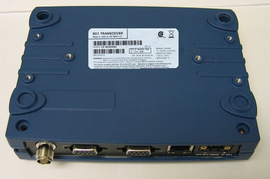
Click to zoom
Application Details
- Equipment Class
- TNB - Licensed Non-Broadcast Station Transmitter
- Date of Grant
- Feb 10, 2011
- Application Purpose
- Original Equipment
- Date of Application
- Feb 10, 2011
- Equipment Note
- Wireless Data Transceiver
- Frequency Range
- 150.00000000 - 174.00000000
- Company
- GE MDS, LLC
- Country
- United States
Documents & Files
Document Text
Text extracted from the exhibit documents filed with the FCC. Open a document above to read the original.
Users Manual
05-6358A01, Rev. 02 (FCC)MDS SD Series Quick Start Guide (x710 Mode)1 MDS SD1 Transceiver Quick Start Guide (x710 Mode) The MDS SD1 transceiver (Figure 1) is a software-configurable, industrial solution for use in wireless telemetry applications. The unit operates in the 150-174 MHz frequency band. The radio interfaces with a variety of data control equipment such as remote terminal units (RTUs), programmable logic controllers (PLCs), flow computers, and similar devices. Data interface con- nections may be made by both serial (RS-232/485) and limited Ethernet protocols. Invisible place holder Figure 1. MDS SD1 Data Transceiver There are three main requirements for installing the transceiver: • Adequate and stable primary power • An efficient and properly installed antenna system • Correct interface connections between the transceiver and the data device. Figure 2 shows a typical installation of the radio. NOTE:Retrofit Kits are available to simplify installation at former MDS x710 digital and analog sites. Consult the Refer- ence Manual for ordering details. 2.1Installation Steps In most cases, the steps given here are sufficient to install the transceiver. Refer to the Reference Manual for additional details, as required. 1.Mount the transceiver using the brackets supplied. Attach the brackets to the bottom of the transceiver case (if not already attached), using the four 6-32 x 1/4 inch (6 mm) screws supplied. Mounting bracket dimensions are shown in Figure 3. If DIN Rail mounting brackets are to be used, consult the Reference Manual. NOTE:To prevent moisture from entering the radio, do not mount the case with the cable connectors pointing up. Also, dress all cables to prevent moisture from running along the cables and into the radio. CAUTION:Using screws longer than 1/4 inch (6 mm) to attach the brackets to the radio may cause internal damage. Use only the screws supplied. Figure 2. Typical Installation (Remote Site Shown) Figure 3. Mounting Bracket Dimensions 2.Install the antenna and feedline. The antenna used with the radio must be designed to operate in the radio’s frequency band, and be mounted in a location providing a clear path to the associated station(s). At Remote sites, aim directional antennas toward the Master Station. Low loss coaxial feedline should be used and it should be kept as short as possible. 3.Connect the data equipment. Connection may be made to the COM port using Serial protocols (RS-232/RS-485). • Connect your data equipment to the appropriate serial port on the front panel. (Typically, COM2 is used for connecting data equipment, and COM1 is used for management of the radio. Other arrangements are possible. Refer to the Refer- ence Manual for details.) In all cases, the radio is hardwired as a DCE device. A straight-thru cable may be used for most applications. 4.Connect primary power. Input power must be 10.0 to 30 Vdc and capable of providing at least 2.5 Amperes. A power con- nector with screw-terminals is provided with the unit (see 1.0INTRODUCTION 2.0INSTALLATION ANTENNA CONNECTOR (TNC) SERIAL DATA CONNECTORS (DB-9) DC INPUT POWER LED INDICATOR PANEL ETHERNET CONNECTOR (RJ-45) COM1 used for radio management DC POWER SUPPLY Negative Ground Only TRANSCEIVER LOW-LOSS FEEDLINE ANTENNA SYSTEM SERIAL Master Stations typically use omni-directional antenna TO DATA TELEMETRY DEVICE 7.25 ̋ (16.99 cm) 2.75 ̋ (7 cm) 2MDS SD Series Quick Start Guide (x710 Mode)05-6358A01, Rev. 02 (FCC) Figure 4). Strip the wire leads to 6 mm (1/4 inch) and insert them into the wire ports. Be sure to observe proper polarity as shown below. Tighten the binding screws securely. Figure 4. DC Power Connector CAUTION:The unit is designed for use with negative-ground systems only. The power supply should be equipped with overload protection (NEC Class 2 rating), to protect against a short circuit between its output termi- nals and the radio’s power connector. 5.Set the radio’s configuration. Connect a PC to the radio’s COM1 port as shown in Figure 5. A straight-thru cable may be used for this connection. NOTE:Consult your System Administrator if you are unsure of the settings required for your network. Figure 5. Setup for PC Configuration 2.1.1 Software Configuration There are two methods for communicating with the radio for con- figuration and management: Serial (COM1 DB9 connector) and Telnet (ETHERNET RJ-45 connector). Both present identical functionality, but the method of access is different for each. The focus here is on Serial access, but Telnet may be used by following these additional points, which replace Steps 1 and 2 below: • For Telnet, connect to the radio with a PC that is on the same IP network as the transceiver. Launch a Telnet pro- gram, and connect to the radio using its programmed IP address. • The default IP address is 192.168.1.1. If you do not know the IP address of the radio, use the serial configuration steps below to view the address with the IPCONFIG command. 1. With a PC connected to the COM1 serial port, launch a terminal program, such as HyperTerminal (included with most pre-Vista Windows®-based PCs) and set the following parameters: 8 bits, no parity, one stop bit (8N1), flow control disabled, VT100 emulation. The radio’s COM1 port automatically determines the connected baud rate (within the range of 1200–115200 bps). 2. Press the key followed by a series of keypresses (1/2 second intervals) until the > prompt appears. The radio is now ready to accept commands. 3. Set/verify the RX (receive) and TX (transmit) frequencies. To set the receive frequency, enter RX followed by the correct fre- quency in MHz (xxx.xxxxx). Press . To set the transmit frequency, enter TX followed by the correct frequency in MHz (xxx.xxxxx). Press . 4. The factory default modem settings support operation for most systems. Other options are available using the proper soft- ware commands. The current setting may be viewed using the MODEM command. Use MODEM [xxxx] if changes are require…
Text truncated - open the document above for the full version.
Attestation Statements
175 Science Parkway, Rochester, New York 14620 USA (585) 242-9600 Phone (585) 242-9620 Fax Feb 9th, 2011 Subject: FCC Narrowbanding support for Canada and the USA Applicant: GE MDS LLC. Product: MDS SD1 FCC ID: E5MDS-SD1 Dear Sir/Madam, Elliott TCB 684 West Maude Ave. Sunnyvale, CA. 94085 The SD1 product uses a software programmable control that will be configured by “Country Specific” settings that will lock the channel bandwidths to a maximum of 12.5KHz for the USA and allow 25KHz for Canada shipments. The SD1 data rate efficiency required per part 90 is in full compliance. Part 90.203(j)(3) states: Applications for part 90 certification of transmitters designed to operate on frequencies in the 150.8–162.0125 MHz, 173.2–173.4 MHz, and/or 421–512 MHz bands, received on or after February 14, 1997 must include a certification that the equipment meets a spectrum efficiency standard of one voice channel per 12.5 kHz of channel bandwidth. Additionally, if the equipment is capable of transmitting data, has transmitter output power greater than 500 mW, and has a channel bandwidth of more than 6.25 kHz, the equipment must be capable of supporting a minimum data rate of 4800 bits per second per 6.25 kHz of channel bandwidth If you have any queries, please do not hesitate to contact me at 585 242-8440: Yours truly, Dennis McCarthy Agency Compliance Engineer GE Digital Energy -MDS 175 Science Parkway Rochester NY 14620 Phone (585) 242-8440 Email [email protected]
Cover Letter(s)
Page 1 of 1 Elliott TCB 684 W. Maude Ave Sunnyvale, CA, 94085 To whom it may concern: The enclosed documents constitute a formal submittal and application for Equipment Authorization for a 150-174 MHz narrowband licensed radio pursuant to the following rules: RSS-Gen Issue 2, June 2007, “General Requirements and Information for the Certification of Radiocommunication Equipment” RSS-119, Issue 10, April 2010, “Land Mobile and Fixed Radio Transmitters and Receivers Operating in the Frequency Range 27.41-960 MHz” FCC Part 90, “Private Land Mobile Radio Services” Per FCC 90.203(j)(5), The GE MDS model SD1 modems transport data (not voice) at the interface rates listed below. MODEM Sustained Serial Data Rate (bps) Channel BW KHz TX Response 4800F 3-level FSK 4800 6.25 KHz Root-duobinary 9600 3-level FSK 9600 12.5 KHz Root-duobinary Elliott Laboratories, as duly authorized agent prepared this submittal. A copy of the letter of our appointment as agent is included with the application. If there are any questions or if further information is needed, please contact Elliott Laboratories for assistance. Sincerely, David W. Bare Chief Engineer
Cover Letter(s)
175 Science Parkway, Rochester, New York 14620 USA (585) 242-9600 Phone (585) 242-9620 Fax Jan 11th, 2011 FEDERAL COMMUNICATIONS COMMISSION 7435 Oakland Mills Road Columbia, MD 21046 U.S.A. Subject: Authority to Act as an Agent to FCC & IC (industry Canada) Applicant: GE MDS LLC. Product: MDS SD1 FCC ID: E5MDS-SD1 Dear Sir/Madam, Elliott TCB 684 West Maude Ave. Sunnyvale, CA. 94085 This is your letter of authorization to accept our appointment of Elliott Laboratories, Inc. as our Agent for GE MDS LLC, to sign applications before Elliott TCB and to make representations to you on our behalf. Elliott Laboratories, Inc. is to receive and exchange data between our company and Elliott TCB. If you have any queries, please do not hesitate to contact me at 585 242-8440: Yours truly, Dennis McCarthy Agency Compliance Engineer GE Digital Energy -MDS 175 Science Parkway Rochester NY 14620 Phone (585) 242-8440 Email [email protected]
Cover Letter(s)
175 Science Parkway, Rochester, New York 14620 USA (585) 242-9600 Phone (585) 242-9620 Fax 1/11/2011 FEDERAL COMMUNICATIONS COMMISSION 7435 Oakland Mills Road Columbia, MD 21046 U.S.A. Subject: Request for withholding from public disclosure the schematic diagrams and system block diagrams pursuant to an application for certification . Applicant: GE MDS LLC Product: Data Transceiver MDS SD1 Model: MDS SD1 FCC ID: E5MDS-SD1 Dear Sir/Madam, We, Microwave Data Systems, would like to request that the schematic diagrams, system block diagram, Theory of Operation and Bill of Materials submitted with the application for certification be withheld from public disclosure as per Section 0.459 of FCC Rules. This request is made under the provisions of Section 0.457(d) of the Commission's Rules, and Section 552(b)(4) of the Freedom of Information Act. These sections authorize as a withholding from public inspection materials which would be privileged as a matter of law if retained by the person submitting them, and materials which would not customarily be released to the public by that person. If you have any queries, please do not hesitate to contact me at 585 242-8440: Yours truly, Dennis McCarthy Agency Compliance Engineer GE Digital Energy -MDS 175 Science Parkway Rochester NY 14620 Phone (585) 242-8440 Email [email protected]
RF Exposure Info
EMC Test Data Client: Contact: Standard: Test Specific Details General Test Configuration No 1.8 Model: SD1 T-Log Number: T81609 Account Manager: Susan Pelzl GE MDS LLCJob Number: J81584 Dennis McCarthy FCC Parts 15 & 90, RSS-GEN and RSS-119Class: N/ A Maximum Permissible Exposure Objective: The objective of this test session is to perform final qualification testing of the EUT with respect to the specification listed above. Test Engineer: John Caizzi Date of Test: 1/5/2011 No modifications were made to the EUT during testing Deviations From The Standard No deviations were made from the requirements of the standard. Calculation uses the free space transmission formula: S = (PG)/(4 πd 2 ) Where: S is power density (W/m 2 ), P is output power (W), G is antenna gain relative to isotropic, d is separation distance from the transmitting antenna (m). Summary of Results Device complies with Power Density requirements at 20cm separation: If not, required separation distance (in m): Modifications Made During Testing T81609 GE MDS.xlsMPE CalcPage 1 of 2 EMC Test Data Client: Contact: Standard: Model: SD1 T-Log Number: T81609 Account Manager: Susan Pelzl GE MDS LLCJob Number: J81584 Dennis McCarthy FCC Parts 15 & 90, RSS-GEN and RSS-119Class: N/ A Use: General Antenna: Cable AntPower Freq.LossGainat AntEIRP MHzdBmmW*dBdBidBmmW 15037.04965.909.1537.040831.94 16237.04965.909.1537.040831.94 17437.04965.909.1537.040831.94 For the cases where S > the MPE Limit Fre q. MHz 150 162 174 8.120.116 EUTPower Density (S)MPE Limit Powe rat 20 cmat 20 cm mW/cm^2mW/cm^2 at 20 cmat 20 cmS <= MPE Limit Power Density (S)MPE LimitDistance where 8.120.100180.3 8.120.100 8.120.108 8.120.116167.4 8.120.108173.5 mW/cm^2mW/cm^2cm T81609 GE MDS.xlsMPE CalcPage 2 of 2
Test Report
File: R81830 Page 1 of 20 Radio Test Report FCC Part 90 and RSS 119 (150 MHz to 174 MHz) Model: SD1 COMPANY: GE MDS LLC 175 Science Parkway Rochester, NY 14620 TEST SITE(S): Elliott Laboratories 41039 Boyce Road. Fremont, CA. 94538-2435 REPORT DATE: February 3, 2011 FINAL TEST DATES: January 5, 6, 7 and 12, 2011 AUTHORIZED SIGNATORY: ______________________________ David W. Bare Chief Engineer Elliott Laboratories LLC Elliott Laboratories is accredited by the A2LA, certificate number 2016-01, to perform the test(s) listed in this report, except where noted otherwise. This report shall not be reproduced, except in its entirety, without the written approval of Elliott Laboratories Elliott Laboratories -- EMC Department Test Report Report Date: February 3, 2011 File: R81830 Page 2 of 20 REVISION HISTORY Rev# Date Comments Modified By - 2-3-2011 First release Elliott Laboratories -- EMC Department Test Report Report Date: February 3, 2011 File: R81830 Page 3 of 20 TABLE OF CONTENTS REVISION HISTORY .............................................................................................................................................. 2 TABLE OF CONTENTS .......................................................................................................................................... 3 SCOPE........................................................................................................................................................................ 4 OBJECTIVE .............................................................................................................................................................. 5 STATEMENT OF COMPLIANCE......................................................................................................................... 5 DEVIATIONS FROM THE STANDARDS ............................................................................................................ 5 TEST RESULTS........................................................................................................................................................ 6 FCC PART 90 AND RSS-119.................................................................................................................................. 6 EXTREME CONDITIONS .................................................................................................................................... 6 MEASUREMENT UNCERTAINTIES..................................................................................................................7 EQUIPMENT UNDER TEST (EUT) DETAILS .................................................................................................... 8 GENERAL.............................................................................................................................................................. 8 OTHER EUT DETAILS......................................................................................................................................... 8 ENCLOSURE......................................................................................................................................................... 8 MODIFICATIONS................................................................................................................................................. 8 SUPPORT EQUIPMENT....................................................................................................................................... 8 EUT INTERFACE PORTS .................................................................................................................................... 9 EUT OPERATION ................................................................................................................................................. 9 TESTING ................................................................................................................................................................. 10 GENERAL INFORMATION ............................................................................................................................... 10 RF PORT MEASUREMENT PROCEDURES .................................................................................................... 11 OUTPUT POWER................................................................................................................................................ 11 BANDWIDTH MEASUREMENTS ....................................................................................................................12 CONDUCTED SPURIOUS EMISSIONS............................................................................................................ 12 TRANSMITTER MASK MEASUREMENTS..................................................................................................... 13 FREQUENCY STABILITY ................................................................................................................................. 13 TRANSIENT FREQUENCY BEHAVIOR:......................................................................................................... 13 RADIATED EMISSIONS MEASUREMENTS.................................................................................................... 14 INSTRUMENTATION ........................................................................................................................................ 15 FILTERS/ATTENUATORS ................................................................................................................................ 15 ANTENNAS......................................................................................................................................................... 15 ANTENNA MAST AND EQUIPMENT TURNTABLE ..................................................................................... 16 SAMPLE CALCULATIONS .............................................................................................…
Text truncated - open the document above for the full version.
Contact Information
Applicant
John Barenys(Senior Operations Manager)
Test Firm
NTS Labs, LLC Fremont & NewarkDavid Bare
Technical Specifications
| # | Rule Parts | Frequency Range | Power Output | Emission | Tolerance |
|---|---|---|---|---|---|
| 6 | 9 | 150 MHz - 174 MHz | 5 W | 9K33F3D | 1 ppm |
Other Applications from GE MDS, LLC

E5MDS-NET9S
Jul 13, 2023Frequency Hopping Radio
Equipment Class
DSS - Part 15 Spread Spectrum Transmitter
E5MDS-NET9L
Jul 11, 2023Frequency Hopping Radio
Equipment Class
DSS - Part 15 Spread Spectrum Transmitter
E5MDS-LN900
Jan 27, 2016Industrial Radio Module
Equipment Class
TNB - Licensed Non-Broadcast Station Transmitter
E5MDS-SDM4
Aug 20, 2015MDS SDM4 Licensed Spectrum Module
Equipment Class
TNB - Licensed Non-Broadcast Station Transmitter
E5MDS-LN400
Jul 09, 2015Industrial Radio Module
Equipment Class
TNB - Licensed Non-Broadcast Station Transmitter