E5MDS-SD4SD4 Data Transceiver
GE MDS, LLC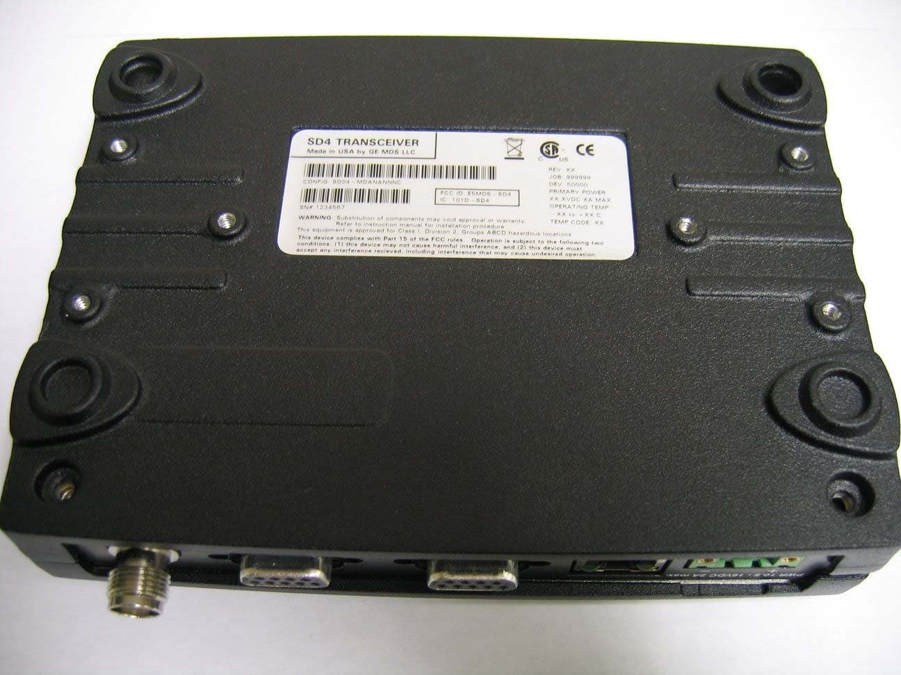
Click to zoom
Application Details
- Equipment Class
- TNB - Licensed Non-Broadcast Station Transmitter
- Date of Grant
- Mar 03, 2008
- Application Purpose
- Original Equipment
- Date of Application
- Feb 14, 2008
- Equipment Note
- SD4 Data Transceiver
- Frequency Range
- 406.10000000 - 512.00000000
- Company
- GE MDS, LLC
- Country
- United States
Documents & Files
Document Text
Text extracted from the exhibit documents filed with the FCC. Open a document above to read the original.
Users Manual
Start-Up Guide Firmware Release 1.x.x MDS 05-4669A01, Rev. A December 2007 MDS SD4 ™ Software-Controlled Digital Communications OPERATIONAL & SAFETY NOTICES Concentrated energy from a directional antenna may pose a health hazard to humans. Do not allow people to come closer to the antenna than the distances listed in the table below when the transmitter is operating. More information on RF exposure can be found online at the following website: www.fcc.gov/oet/info/documents/bulletins. FCC Part 15 Notice (Pending Approval) The transceiver is approved under Part 15 of the FCC Rules. Operation is subject to the following two con- ditions: (1) this device may not cause harmful interference, and (2) this device must accept any interfer- ence received, including interference that may cause undesired operation. Any unauthorized modification or changes to this device without the express approval of Microwave Data Systems may void the user’s authority to operate this device. Furthermore, this device is intended to be used only when installed in accordance with the instructions outlined in this manual. Failure to comply with these instructions may void the user’s authority to operate this device. CSA/us Notice (Pending Approval) This product is pending approval for use in Class 1, Division 2, Groups A, B, C & D Hazardous Locations. Such locations are defined in Article 500 of the National Fire Protection Association (NFPA) publication NFPA 70, otherwise known as the National Electrical Code. The transceiver has been recognized for use in these hazardous locations by the Canadian Standards Association (CSA) which also issues the US mark of approval (CSA/US). The CSA Certification is in accordance with CSA STD C22.2 No. 213-M1987. CSA Conditions of Approval: The transceiver is not acceptable as a stand-alone unit for use in the hazardous locations described above. It must either be mounted within another piece of equipment which is certified for hazardous locations, or installed within guidelines, or conditions of approval, as set forth by the approving agencies. These conditions of approval are as follows: The transceiver must be mounted within a separate enclosure which is suitable for the intended application. The antenna feedline, DC power cable and interface cable must be routed through conduit in accordance with the National Electrical Code. Installation, operation and maintenance of the transceiver should be in accordance with the transceiver's installation manual, and the National Electrical Code. Tampering or replacement with non-factory com- ponents may adversely affect the safe use of the transceiver in hazardous locations, and may void the approval. A power connector with screw-type retaining screws as supplied by GE MDS must be used. Do not disconnect equipment unless power has been switched off or the area is known to be non-hazardous. Refer to Articles 500 through 502 of the National Electrical Code (NFPA 70) for further information on hazardous locations and approved Division 2 wiring methods. Antenna Gain vs. Recommended Safety Distance (MDS SD4 Radio) Antenna Gain 0–5 dBi5–10 dBi10–16.5 dBi Minimum RF Safety Distance 0.79 meter1.41 meters3.05 meters RF Exposure EXPLOSION HAZARD! 05-4669A01, Rev. AMDS SD4 Startup Guide 1 INTRODUCTION This guide presents basic installation and operating instructions for the MDS SD4 Series wireless transceiver. It is a companion guide to the MDS SD4 Series Reference Manual (Part No. 05-4670A01). Refer to the Reference Manual for additional details and system design infor- mation. The transceiver (Figure 1) is designed to operate in point-to-multi- point environments, including utility automation/distribution systems, and other telemetry functions. These radios are software-configurable to provide flexible operation in a variety of applications using one hardware platform. They employ microprocessor control and Digital Signal Processing (DSP) tech- nology to provide robust communications even under adverse condi- tions. Figure 1. SD4 Data Transceiver The transceiver is designed for trouble-free operation with data equip- ment provided by other manufacturers, including remote terminal units (RTUs), programmable logic controllers (PLCs), flow com- puters, transaction terminals, and other similar devices. NOTE: Some features may not be available on all units, based on the options purchased and the applicable regulatory constraints for the region in which the radio will operate. Front Panel Layout Figure 2 shows the interface connectors and indicators on the trans- ceiver’s front panel. These items are referenced in the installation steps given later in this guide. 2MDS SD4 Startup Guide05-4669A01, Rev. A Invisible place holder Figure 2. Front Panel Connectors & Indicators Connector functions (left to right) are as follows: •POWER • LAN (RJ-45) • COM1— Management/Diagnostics (DB-9) • COM2— Payload Data (DB-9) • ANTENNA (TNC) LED functions are described in Table 3 on Page 9. Standard Accessories Table 1 lists accessories normally shipped with the transceiver. The contents may have been modified to reflect customer-specific require- ments specified at the time of order. Additional accessories are avail- able. Refer to the SD4 Reference Manual for a complete list. 05-4669A01, Rev. AMDS SD4 Startup Guide 3 INSTALLATION There are three main requirements for installing the transceiver: ade- quate and stable primary power, a good antenna system, and the cor- rect data connections between the transceiver and the data device. Figure 3 shows a typical remote station arrangement. This is followed by step-by-step procedures for installing the transceiver and making external connections. Table 1. Accessories Supplied with the Unit AccessoryDescriptionPart Number DC Power Plug, 2-pin, polarized Mates with power connector on radio. Screw terminals provided for wires, threaded locking screws to prevent accidental disconnect. 73-1194A39 Radio Configuration Software PC soft…
Text truncated - open the document above for the full version.
Attestation Statements
175 Science Parkway, Rochester, New York 14620 USA (585) 242-9600 Phone (585) 242-9620 Fax Feb 21st, 2008 FEDERAL COMMUNICATIONS COMMISSION 7435 Oakland Mills Road Columbia, MD 21046 U.S.A. ATCB 6731 Whittier Ave Mclean Va 22101 Subject: GE MDS New digital radio part 90 frequency bands Applicant: GE MDS LLC Product: SD4 digital transceiver FCC ID: E5MDS-SD4 Dear Sir/Madam, The SD4 digital radio is hardware banded into 3 frequency selective bands which cover 406.1-512MHz. These bands are built depending on the customer frequency ordered. This device is designed to operate under the part 90 rules in the following sub bands 406.1-416 MHz, 421-430MHz, 450-512MHz. Emission designators are; 9K25F1D, 9K25F2D, 9K25F3D, also 16K5F1D, 16K5F2D, 16K5F3D. This letter serves as attestation supporting evidence for the frequency banding. If you have any queries, please do not hesitate to contact me at 585 242-8440: Yours truly, Dennis McCarthy Agency Compliance Engineer GE MDS LLC 175 Science Parkway Rochester NY 14620 Phone (585) 242-8440 Email [email protected]
Cover Letter(s)
175 Science Parkway, Rochester, New York 14620 USA (585) 242-9600 Phone (585) 242-9620 Fax Jan 10th, 2008 FEDERAL COMMUNICATIONS COMMISSION 7435 Oakland Mills Road Columbia, MD 21046 U.S.A. Subject: Authority to Act as an Agent to FCC & IC (industry Canada) Applicant: GE MDS LLC. Product: MDS SD4 FCC ID: E5MDS-SD4 Dear Sir/Madam, American Telecommunications Certification Body 6731 Whittier Avenue Suite C110 McLean, VA 22101 This is your letter of authorization to accept our appointment of ATCB. as our Agent for GE MDS LLC, to sign applications before ATCB and to make representations to you on our behalf. ATCB, is to receive and exchange data between our company and ATCB. If you have any queries, please do not hesitate to contact me at 585 242-8440: Yours truly, Dennis McCarthy Agency Compliance Engineer Microwave Data Systems 175 Science Parkway Rochester NY 14620 Phone (585) 242-8440 Email [email protected]
Cover Letter(s)
175 Science Parkway, Rochester, New York 14620 USA (585) 242-9600 Phone (585) 242-9620 Fax Jan 7th, 2008 FEDERAL COMMUNICATIONS COMMISSION 7435 Oakland Mills Road Columbia, MD 21046 U.S.A. Subject: Request for withholding from public disclosure the schematic diagrams and system block diagrams pursuant to an application for certification . Applicant: GE MDS LLC Product: Data Transceiver MDS SD4 Model: MDS SD4 FCC ID: E5MDS-SD4 Dear Sir/Madam, We, Microwave Data Systems, would like to request that the schematic diagrams, system block diagram, Theory of Operation and Bill of Materials submitted with the application for certification be withheld from public disclosure as per Section 0.459 of FCC Rules. This request is made under the provisions of Section 0.457(d) of the Commission's Rules, and Section 552(b)(4) of the Freedom of Information Act. These sections authorize as a withholding from public inspection materials which would be privileged as a matter of law if retained by the person submitting them, and materials which would not customarily be released to the public by that person. If you have any queries, please do not hesitate to contact me at 585 242-8440: Yours truly, Dennis McCarthy Agency Compliance Engineer Microwave Data Systems 175 Science Parkway Rochester NY 14620 Phone (585) 242-8440 Email [email protected]
Cover Letter(s)
File: R70437 January 17, 2008 A TCB Gentlemen: The enclosed documents constitute a formal submittal and request for a Certification pursuant to Part 90 of FCC Rules (CFR 47) regarding to Public Mobile Service. Certification is being requested for GE MDS LLC model SD4. The SD4 has been tested and found to comply with FCC Part 90 limits. Elliott Laboratories, as duly authorized agent prepared this submittal. A copy of the letter of our appointment as agent is enclosed. If there are any questions or if further information is needed, please contact Elliott Laboratories for assistance. Sincerely, David W. Bare Chief Technical Officer DWB/dmg Enclosures: Application forms Emissions Test Report with Exhibits File: R70437 January 17, 2008 ATCB Gentlemen: The enclosed documents constitute a formal submittal and request for a Certification pursuant to RSS-119, Issue 9 (Land Mobile and Fixed Radio Transmitters and Receivers, 27.41 to 960 MHz). Certification is being requested for GE MDS LLC model SD4. The SD4 has been tested and found to comply with RSS-119, issue 9 limits. Elliott Laboratories, as duly authorized agent prepared this submittal. A copy of the letter of our appointment as agent is enclosed. If there are any questions or if further information is needed, please contact Elliott Laboratories for assistance. Sincerely, David W. Bare Chief Technical Officer DWB/dmg Enclosures: Application Forms Emissions Test Report with Exhibits
Cover Letter(s)
Page 1 of 1 American TCB January 30, 2008 RE: FCC ID:E5MDS-SD4 Attention: Douglas E. Noble Please find our responses to your comments on this application below: 1. Please submit a REL listing cover letter for Industry Canada. Uploaded file “IC ATCB REL listing letter.pdf” 2. Please submit Label drawing and Label location photo in label and location exhibit. Uploaded file “Label and label location drawing.pdf” 3. Please submit RF Exposure Info exhibit that justifies the distances that are quoted in the user manual for minimum safe distance according to antenna gain. Uploaded file “MPE Calculation.pdf” Regards, Dave Guidotti Senior Documentation Specialist
RF Exposure Info
EMC Test Data Client: Contact: Standard: Test Specific Details General Test Configuration No 0.69 1.21 2.6 GE MDS LLCJob Number: J69634 Model: SD4 T-Log Number: T69922 Account Manager: Susan Pelzl Dennis McCarthy FCCClass: N/ A Maximum Permissible Exposure Objective: The objective of this test session is to perform final qualification testing of the EUT with respect to the specification listed above. Date of Test: 1/21/2008 Test Engineer: David Bare Calculation uses the free space transmission formula: S = (PG)/(4 πd 2 ) Where: S is power density (W/m 2 ), P is output power (W), G is antenna gain relative to isotropic, d is separation distance from the transmitting antenna (m). Summary of Results Device complies with Power Density requirements at 20cm separation: Required separation distance for 5dBi ant. (in m): Modifications Made During Testing No modifications were made to the EUT during testing Deviations From The Standard No deviations were made from the requirements of the standard. Required separation distance for 10dBi ant. (in m): Required separation distance for 16.5dBi ant. (in m): T69922MPE Calc 21-Jan-08Page 1 of 2 EMC Test Data Client: Contact: Standard: GE MDS LLCJob Number: J69634 Model: SD4 T-Log Number: T69922 Account Manager: Susan Pelzl Dennis McCarthy FCCClass: N/ A Use: General Cable AntPower Freq.LossGainat AntEIRP MHzdBmmW*dBdBidBmmW 406.137.15128.60 5 37.116218.10 45037.45495.40 5 37.417378.01 51237.15128.60 5 37.116218.10 For the cases where S > the MPE Limit Fre q. MHz 406.1 450 512 Cable AntPower Freq.LossGainat AntEIRP MHzdBmmW*dBdBidBmmW 406.137.15128.60 10 37.151286.14 45037.45495.40 10 37.454954.09 51237.15128.60 10 37.151286.14 For the cases where S > the MPE Limit Fre q. MHz 406.1 450 512 Cable AntPower Freq.LossGainat AntEIRP MHzdBmmW*dBdBidBmmW 406.137.15128.60 16.5 37.1229086.77 45037.45495.40 16.5 37.4245470.89 51237.15128.60 16.5 37.1229086.77 For the cases where S > the MPE Limit Fre q. MHz 406.1 450 512 EUTPower Density (S)MPE Limit Powe rat 20 cmat 20 cm mW/cm^2mW/cm^2 3.2260.271 3.4570.300 3.2260.341 at 20 cmat 20 cmS <= MPE Limit Power Density (S)MPE LimitDistance where 3.2260.271 69.0 mW/cm^2mW/cm^2cm 3.4570.300 67.9 Powe rat 20 cmat 20 cm mW/cm^2mW/cm^2 10.2030.341 10.2030.271 10.9330.300 mW/cm^2mW/cm^2cm at 20 cmat 20 cmS <= MPE Limit 120.7 10.2030.271 122.8 10.2030.341 109.3 10.9330.300 Power Density (S)MPE LimitDistance where EUTPower Density (S)MPE Limit 3.2260.341 61.5 EUTPower Density (S)MPE Limit Powe rat 20 cmat 20 cm mW/cm^2mW/cm^2 45.5750.271 48.8350.300 45.5750.341 at 20 cmat 20 cmS <= MPE Limit Power Density (S)MPE LimitDistance where 45.5750.271 259.5 mW/cm^2mW/cm^2cm 45.5750.341 231.1 48.8350.300 255.2 T69922MPE Calc 21-Jan-08Page 2 of 2
Test Report
File: R70437 Rev 2 Page 1 of 21 Electromagnetic Emissions Test Report In Accordance With Industry Canada Radio Standards Specification 119 Issue 9, FCC Part 90 on the GE MDS LLC Transmitter Model: SD4 FCC ID NUMBER: E5MDS-SD4 UPN: 101D-SD4 GRANTEE: GE MDS LLC 175 Science Parkway Rochester, NY 14620 TEST SITE: Elliott Laboratories, Inc. 684 W. Maude Avenue Sunnyvale, CA 94086 REPORT DATE: January 17, 2008 FINAL TEST DATE: November 13, November 14, November 15, 2007 and January 9 and January 11, 2008 AUTHORIZED SIGNATORY: ______________________________ David W. Bare Chief Technical Officer Elliott Laboratories, Inc. is accredited by the A2LA, certificate number 2016-01, to perform the test(s) listed in this report. This report shall not be reproduced, except in its entirety, without the written approval of Elliott Laboratories, Inc. Testing Cert #2016-01 Elliott Laboratories, Inc. -- EMC Department Test Report Report Date: January 17, 2008 File: R70437 Rev 2 Page 2 of 21 REVISION HISTORY Revision # Date Comments Modified By 1 January 24, 2008 Initial Release David Guidotti 2 February 12, 2008 Added necessary bandwidth calculations David Bare Elliott Laboratories, Inc. -- EMC Department Test Report Report Date: January 17, 2008 File: R70437 Rev 2 Page 3 of 21 TABLE OF CONTENTS COVER PAGE.............................................................................................................................................................1 REVISION HISTORY ................................................................................................................................................2 TABLE OF CONTENTS ............................................................................................................................................3 FCC CERTIFICATION INFORMATION...............................................................................................................5 DECLARATIONS OF COMPLIANCE....................................................................................................................7 SCOPE..........................................................................................................................................................................8 OBJECTIVE ................................................................................................................................................................8 SUMMARY OF TEST RESULTS .............................................................................................................................9 PART 90 AND RSS-119 TEST SUMMARY...............................................................................................................9 MEASUREMENT UNCERTAINTIES ...................................................................................................................10 EQUIPMENT UNDER TEST (EUT) DETAILS ....................................................................................................11 GENERAL..............................................................................................................................................................11 OTHER EUT DETAILS.........................................................................................................................................11 ENCLOSURE.........................................................................................................................................................11 MODIFICATIONS.................................................................................................................................................11 SUPPORT EQUIPMENT.......................................................................................................................................12 EUT INTERFACE PORTS ....................................................................................................................................12 EUT OPERATION DURING TESTING...............................................................................................................12 TEST SITE.................................................................................................................................................................13 GENERAL INFORMATION.................................................................................................................................13 CONDUCTED EMISSIONS CONSIDERATIONS ..............................................................................................13 RADIATED EMISSIONS CONSIDERATIONS ..................................................................................................13 MEASUREMENT INSTRUMENTATION ............................................................................................................14 RECEIVER SYSTEM ............................................................................................................................................14 INSTRUMENT CONTROL COMPUTER ............................................................................................................14 PEAK POWER METER ........................................................................................................................................14 FILTERS/ATTENUATORS ..................................................................................................................................14 ANTENNAS...........................................................................................................................................................15 ANTENNA MAST AND EQUIPMENT TURNTABLE.......................................................................................15 INSTRUMENT CALIBRATION...........................................................................................................................15 TEST PROCEDURES ........................................................................................................…
Text truncated - open the document above for the full version.
Test Report
MARS (SD4) Frequency Stability over Temperature (Below 1.5PPM) Part 90.213 & 2.995 GE MDS LLC. 12/06/07 To verify that the MARS output frequency did not shift by more than 1.5 PPM over the rated operating temperature, testing was done. The test was conducted in an environmental chamber with the temperature ranging from –30 to 50ºC. The radio was operational during the entire part of the test with control line, power line and antenna line coming out of the chamber. The temperature was incremented by 10ºC and once the thermocouple probe had reached the desired temperature the radio was soaked an additional 15 minutes at that temperature to be certain. Frequency stability was then measured on a communications test set (Aeroflex 3920). Below are the results of the temperature testing. Radio: MDS MARS (SER 1699863) MDS MARS Nominal Tx Freq (425MHz) 10 V Nominal Supply Voltage 13.8 V 16 V Ambient Temperature (ºC) Freq Error (Hz) PPM Freq Error (Hz)PPM Freq Error (Hz) PPM -30 145 0.341 81 0.191 148 0.348 -20 107 0.252 105 0.247 108 0.254 -10 206 0.485 206 0.485 206 0.485 0 252 0.593 252 0.593 254 0.598 10 294 0.692 295 0.694 290 0.682 20 213 0.501 217 0.511 204 0.480 30 38 0.089 43 0.101 26 0.061 40 - 179 - 0.421 - 173 - 0.407 - 190 - 0.447 50 - 377 - 0.887 - 372 - 0.875 - 388 - 0.913 From the results it is clear that the MDS Mars (SD4) radio meets the 1.5PPM criteria. The set desired frequency being 425.00MHz would indicate the frequency shift would have to be less than (+/-) 637.5 hertz. From the collected data, the largest deviation is at +50ºC@16vdc, which is - 388 Hz, which is well inside the (+/-) 637.5 Hz or (+/-)1.5ppm spec.
Contact Information
Applicant
John Barenys(Senior Operations Manager)
Technical Contact
Elliott LabsDavid Bare
[email protected]408-245-7800
684 West Maude Ave · Sunnyvale, California · United States
Test Firm
Element Materials Technology Fremont NewarkDavid Bare
Technical Specifications
| # | Rule Parts | Frequency Range | Power Output | Emission | Tolerance |
|---|---|---|---|---|---|
| 12 | 9 | 406.1 MHz - 512 MHz | 100.00 mW | 23K4F3D | 388 Hz |
Other Applications from GE MDS, LLC

E5MDS-NET9S
Jul 13, 2023Frequency Hopping Radio
Equipment Class
DSS - Part 15 Spread Spectrum Transmitter
E5MDS-NET9L
Jul 11, 2023Frequency Hopping Radio
Equipment Class
DSS - Part 15 Spread Spectrum Transmitter
E5MDS-LN900
Jan 27, 2016Industrial Radio Module
Equipment Class
TNB - Licensed Non-Broadcast Station Transmitter
E5MDS-SDM4
Aug 20, 2015MDS SDM4 Licensed Spectrum Module
Equipment Class
TNB - Licensed Non-Broadcast Station Transmitter
E5MDS-LN400
Jul 09, 2015Industrial Radio Module
Equipment Class
TNB - Licensed Non-Broadcast Station Transmitter