E5MDS-SDM9MDS SDM9 Licensed Spectrum Module
GE MDS, LLC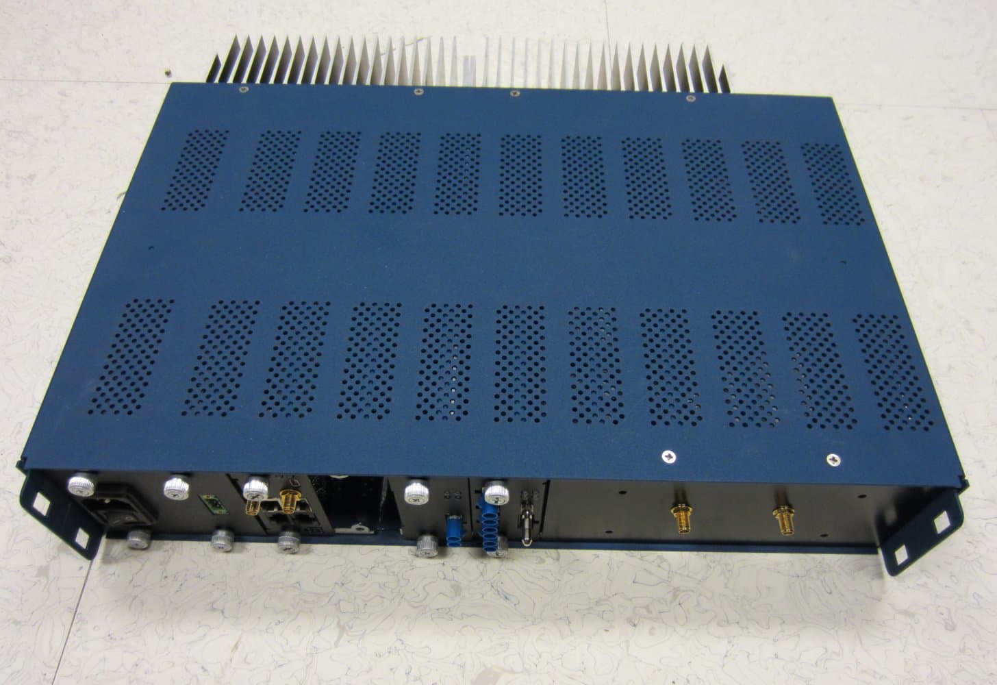
Click to zoom
Application Details
- Equipment Class
- PCB - PCS Licensed Transmitter
- Date of Grant
- Mar 03, 2014
- Application Purpose
- Original Equipment
- Date of Application
- Feb 23, 2014
- Equipment Note
- MDS SDM9 Licensed Spectrum Module
- Frequency Range
- 928.00000000 - 960.00000000
- Company
- GE MDS, LLC
- Country
- United States
Documents & Files
Document Text
Text extracted from the exhibit documents filed with the FCC. Open a document above to read the original.
Users Manual
MDS SDM9 Quick Start Guide (x790 Mode) The MDS SDM9 transceiver (Figure 1) is a software- configurable, industrial Master Station solution for use in wireless telemetry applications. In this guide, the term SD is used for information common to all models of the radio. This radio module is designed for use with a card cage and backplane similar to that shown in Figure 3, and to be used with a variety of data control equipment such as remote terminal units (RTUs), programmable logic controllers (PLCs), flow computers, and similar devices. Data interface connections may be made by both serial (RS- 232/485) and limited Ethernet protocols. Invisipbllhaeoc led er Figure 1. MDS SDM9 Data Transceiver 1.1 About This Guide This guide covers SDM9 transceivers operating in x710-Compatible Mode. All GE MDS manuals are available free of charge at www.gemds.com. Invisipbllhaeoc led er There are three main requirements for installing the transceiver: • Adequate and stable primary power • An efficient and properly installed antenna system • Correct interface connections between the transceiver and the data device. Figure 2 shows a chassis with card cage and backplane that this module would be typically installed in. The backplane provides the 24V power connection to this unit and provides the customer data interfaces through the card edge connector on the rear of the SDM9. Figure 2: Typical Orbit Master Station Chassis. The SDM9 modules may be installed in any free peripheral slot of this chassis. Figure 3 shows a typical installation of the radio. NOTE: Retrofit Kits are available to simplify installation at former MDS x710 digital and analog sites. Consult the Reference Manual for ordering details. Figure 3: Typical Master Station Chassis with SDM9 radio card installed. NOTE: Chassis has antenna connection in rear, with power and data connections in the front. 2.1 Installation Steps 1. Install the transceiver into chassis as shown in Figure 2. NOTE: To prevent damage to the SDM9 radio, wear a wrist strap to prevent ESD discharge to the card edge connector. Also, dress all cables as required to prevent moisture from running along the cables and into the radio. 1.0 INTRODUCTION 2.0 INSTALLATION MDS SDM9 Quick Start Guide (x790 Mode) 2. Install the antenna and feedline. The antenna used with the radio must be designed to operate in the radio’s frequency band, and be mounted in a location providing a clear path to the associated station(s). At Remote sites, aim directional antennas toward the Master Station. Low loss coaxial feedline should be used and it should be kept as short as possible. 3. Connect the data equipment. Connection may be made to the COM port using Serial protocols (RS- 232/RS-485). RJ45 to DB9/DB25 adapters may be required depending on physical data port connector type used on the data telemetry device to be attached as shown in Figure 3. 4. Connect primary power to the Orbit Chassis. Input power must within the ranges specified for the power supply module installed in the Orbit chassis: 12VDC, 24VDC, 48VDC, 125VDC, or 90-264VAC. These supplies all convert incoming power to +24V for SDM9 Module operation. 5. Set the radio’s configuration. Connect a PC to the radio’s COM1 and COM2 ports as shown in Figure 4. A straight-thru cable may be used for this connection with an RJ45 to DB9 adapter. NOTE: Consult your System Administrator if you are unsure of the settings required for your network. Figure 4. Setup for PC Configuration 2.1.1 Software Configuration There are two methods for communicating with the radio for configuration and management: Serial (COM1, COM2 RJ45 connector) and Telnet (ETHERNET RJ-45 connector). Both present identical functionality and use the same commands, but the method to configure access is different for each. NOTE: Transmitter and Receiver configuration are handled through separate DSP devices, thus two serial ports or two Telnet sessions will be required to handle configuration of these two functions. The focus here is on Serial access, but Telnet may be used by following these additional points, which replace Steps 1 and 2 below: • For Telnet, connect to the radio with a PC that is on the same IP network as the transceiver. Launch a Telnet program, and connect to the radio using its programmed IP address for the Transmitter and Receiver. • The default IP address of the Transmitter configuration is 192.168.1.1. The default IP address of the Receiver configuration is 192.168.1.2. If you do not know the IP address of the radio, use the serial configuration steps below to view the address with the IPCONFIG command. 1. With a PC connected to the COM1 serial port, launch a terminal program, such as HyperTerminal (included withmost pre-Windows7 ®-based PCs) and set the following parameters: 8 bits, no parity, one stop bit (8N1), flow control disabled, VT100 emulation. The COM port automatically finds the connected baud rate (within 1200–115200 bps). 2. Press the ESCAPE key followed by a series of ENTER keypresses (at 1/2 second intervals) until the > prompt appears. The radio is now ready to accept commands. 3. Set/verify the RX (receive) and TX (transmit) frequencies. To set the receive frequency, enter RX followed by the correct frequency in MHz (xxx.xxxxx). Press ENTER . To set the transmit frequency, enter TX followed by the correct frequency in MHz (xxx.xxxxx). Press ENTER. 4. The factory default modem settings support 9600 bps transmission in a 12.5 kHz bandwidth channel. Many other options are available. The current setting may be viewed using the MODEM command. Use MODEM [xxxx] if changes are required. When finished with the steps above, review the other configuration options to determine if other settings are required for your system. Table 3 lists key software commands for the radio. 2.2 Initial Checkout In-service operation is completely automatic. The only operator actions required are to apply DC power and observe the LEDS for proper indications. Table 1 on…
Text truncated - open the document above for the full version.
Cover Letter(s)
175 Science Parkway, Rochester, New York 14620 USA (585) 242-9600 Phone (585) 242-9620 Fax Jan 15th, 2014 American Certification Body, Inc. 6731 Whittier Avenue Suite C110 McLean, VA 22101 Subject: Authority to Act as an Agent to FCC & IC (industry Canada) Applicant: GE MDS LLC. Product: MDS SDM9 To Whom It May Concern: _National Technical Systems – Silicon Valley_ is authorized to act on our behalf, until otherwise notified, for applications to American Certification Body, Inc. (ACB). We certify that we are not subject to denial of federal benefits, that includes FCC benefits, pursuant to Section 5301 of the Anti-Drug Abuse Act of 1988, 21 U.S.C. 862. Further, no party, as defined in 47 CFR 1.2002 (b), to the application is subject to denial of federal benefits, that includes FCC benefits. Thank you, Agency Agreement Expiration Date: _____(Typically 8 – 12 months)_____ Yours truly, Dennis McCarthy Agency Compliance Engineer GE Digital Energy -MDS 175 Science Parkway Rochester NY 14620 Phone (585) 242-8440 Email [email protected]
Cover Letter(s)
175 Science Parkway, Rochester, New York 14620 USA (585) 242-9600 Phone (585) 242-9620 Fax Date: January 15, 2014 Subject: Confidentiality Request for FCC ID: E5MSDM9 Pursuant to FCC 47 CRF 0.457(d) and 0.459 and IC RSP-100, Section 10, the applicant requests that a part of the subject FCC application be held confidential. Type of Confidentiality Requested Exhibit Short Term Permanent Block Diagrams Short Term External Photos Short Term Permanent* 1 Internal Photos Short Term Permanent Operation Description/Theory of Operation Short Term Permanent Parts List & Placement/BOM Short Term Permanent Tune-Up Procedure Short Term Permanent Schematics Short Term Test Setup Photos Short Term Permanent* User’s Manual GE Microwave Data Systems, LLC has spent substantial effort in developing this product and it is one of the first of its kind in industry. Having the subject information easily available to "competition" would negate the advantage they have achieved by developing this product. Not protecting the details of the design will result in financial hardship. Permanent Confidentiality: The applicant requests the exhibits listed above as permanently confidential be permanently withheld from public review due to materials that contain trade secrets and proprietary information not customarily released to the public. Sincerely, Dennis McCarthy Agency Compliance Engineer GE Digital Energy -MDS 175 Science Parkway Rochester NY 14620 Phone (585) 242-8440 Email [email protected]
Cover Letter(s)
175 Science Parkway, Rochester, New York 14620 USA (585) 242-9600 Phone (585) 242-9620 Fax Jan 29th, 2014 Federal Communications Commission Authorization and Evaluation Division 1435 Oakland Mills Road FCC ID: E5MDS-SDM9 Dear Si/Madam: Full Modular Approval is being requested for this device. The following paragraphs detail the requirements for modules and explain how the module meets those requirements. Where requirements are not met a justification for a limited modular approval is presented. FCC §15.212 Requirements for Single Modular Transmitters (includes RSS GEN Section 3.2.2) (a) Single modular transmitters consist of a completely self-contained radiofrequency transmitter device that is typically incorporated into another product, host or device. Split modular transmitters consist of two components: a radio front end with antenna (or radio devices) and a transmitter control element (or specific hardware on which the software that controls the radio operation resides). All single or split modular transmitters are approved with an antenna. All of the following requirements apply, except as provided in paragraph (b) of this section. (1) Single modular transmitters must meet the following requirements to obtain a modular transmitter approval. (i) The radio elements of the modular transmitter must have their own shielding. The physical crystal and tuning capacitors may be located external to the shielded radio elements. The module contains a shield (The radio module has multiple shields over each RF section as well as a shield over the entire top and bottom of the radio module). (ii) The modular transmitter must have buffered modulation/data inputs (if such inputs are provided) to ensure that the module will comply with part 15 requirements under conditions of excessive data rates or over- modulation. Data to the modulation circuit is buffered on the module via the DSPs, U100B, U501B and U400B (iii) The modular transmitter must have its own power supply regulation. The module contains its own power supply regulation and the RF reference oscillator is contained within the module. The Reference Oscillator is a TCXO U1612, The Power supply regulation is provided U1602 switching power supply (iv) The modular transmitter must comply with the antenna and transmission system requirements of §§15.203, 15.204(b) and 15.204(c). The antenna must either be permanently attached or employ a “unique” antenna coupler (at all connections between the module and the antenna, including the cable). The “professional installation” provision of §15.203 is not applicable to modules but can apply to limited modular approvals under paragraph (b) of this section. The module connects to its antenna via J901 a dual SMB snap on RF coax connector This connector is a non- standard connector. The antenna is a Yagi or Omni antenna that is specified at the time of FCC licensing. This module is not FCC part 15, it is FCC part 101 and part 24 licensed spectrum device (v) The modular transmitter must be tested in a stand-alone configuration, i.e., the module must not be inside another device during testing for compliance with part 15 requirements. Unless the transmitter module will be battery powered, it must comply with the AC line conducted requirements found in §15.207. AC or DC power lines and data input/output lines connected to the module must not contain ferrites, unless they will be marketed with the module (see §15.27(a)). The length of these lines shall be the length typical of actual use or, if that length is unknown, at least 10 centimeters to insure that there is no coupling between the case of the module and supporting equipment. Any accessories, peripherals, or support equipment connected to the module during testing shall be unmodified and commercially available (see §15.31(i)). Test data contained in this application is for the device tested in a stand-alone configuration. Radiated spurious emissions data and AC conducted emissions data demonstrating compliance with the requirements of Part 15 of the FCC rules for intentional radiators and RSS GEN/RSS 210 has been provided. A test fixture was supplied to support testing the module in a stand alone configuration (vi) The modular transmitter must be equipped with either a permanently affixed label or must be capable of electronically displaying its FCC identification number. (A) If using a permanently affixed label, the modular transmitter must be labeled with its own FCC identification number, and, if the FCC identification number is not visible when the module is installed inside another device, then the outside of the device into which the module is installed must also display a label referring to the enclosed module. This exterior label can use wording such as the following: “Contains Transmitter Module FCC ID: XYZMODEL1” or “Contains FCC ID: XYZMODEL1.” Any similar wording that expresses the same meaning may be used. The Grantee may either provide such a label, an example of which must be included in the application for equipment authorization, or, must provide adequate instructions along with the module which explain this requirement. In the latter case, a copy of these instructions must be included in the application for equipment authorization. (B) If the modular transmitter uses an electronic display of the FCC identification number, the information must be readily accessible and visible on the modular transmitter or on the device in which it is installed. If the module is installed inside another device, then the outside of the device into which the module is installed must display a label referring to the enclosed module. This exterior label can use wording such as the following: “Contains FCC certified transmitter module(s).” Any similar wording that expresses the same meaning may be used. The user manual must include instructions on how to access the electronic display. A copy of these instructions must be included in the application for equipme…
Text truncated - open the document above for the full version.
Cover Letter(s)
175 Science Parkway, Rochester, New York 14620 USA (585) 242-9600 Phone (585) 242-9620 Fax Feb 27th, 2014 FEDERAL COMMUNICATIONS COMMISSION 7435 Oakland Mills Road Columbia, MD 21046 U.S.A. Subject: Compliance with FCC part 101.131 Applicant: GE MDS LLC. Product: MDS SDM9 Per FCC 101.131 (b), the SDM9 incorporates a modulation filter within the DSP. The channel filter function resides within the DSP after modulation and before the signal is amplified through the transmitter. Per FCC 101.131 (c), The master station radio module incorporates an indicator to display that the transmitter is enabled. If you have any queries, please do not hesitate to contact me at 585 242-8440: Yours truly, Dennis McCarthy Agency Compliance Engineer GE Digital Energy -MDS 175 Science Parkway Rochester NY 14620 Phone (585) 242-8440 Email [email protected]
External Photos
SDM9 chassis outside SDM9 chassis outside back SDM9 bottom shield on SDM9 bottom shield on SDM9 Top cover on SDM9 Top cover on
ID Label/Location Info
2.7/8” 1.25”
Internal Photos
SDM9 bottom shield off SDM9 bottom shield on SDM9 bottom shield on SDM9 Top cover on SDM9 Top cover on SDM9 Top shields off SDM9 Top shields on
RF Exposure Info
EMC Test Data Client: Contact: Standard: Test Specific Details General Test Configuration No GE MDS LLCJob Number: J93834 Model: Radio Card SDM9 T-Log Number: T93925 Project Manager: Christine Krebill Dennis McCarthyProject Coordinator: Irene Rademacher FCC Parts 24 and 101, RSS-119Class: N/A Maximum Permissible Exposure Objective: The objective of this test session is to perform final qualification testing of the EUT with respect to the specification listed above. Date of Test: January 24, 214 Test Engineer: Deniz Demirci Calculation uses the free space transmission formula: S = (PG)/(4 πd 2 ) Where: S is power density (W/m 2 ), P is output power (W), G is antenna gain relative to isotropic, d is separation distance from the transmitting antenna (m). Summary of Results Device complies with Power Density requirements at 20cm separation: 104 Deviations From The Standard No deviations were made from the requirements of the standard. If not, required separation distance (in cm): Modifications Made During Testing No modifications were made to the EUT during testing T93925 GE MDS LLC (Orbit Module).xlsMPE Calc 24-Jan-14Page 1 of 2 EMC Test Data Client: Contact: Standard: GE MDS LLCJob Number: J93834 Model: Radio Card SDM9 T-Log Number: T93925 Project Manager: Christine Krebill Dennis McCarthyProject Coordinator: Irene Rademacher FCC Parts 24 and 101, RSS-119Class: N/A Use: General Antenna:9.15 FOR 300-1500 MHz sin gle transmitters Cable Loss AntPower Freq.LossGainat AntEIRP MHzdBmmW*dBdBidBmmW 92840.110232.909.1540.184139.51 94140.110232.909.1540.184139.51 96040.110232.909.1540.184139.51 For the cases where S > the MPE Limit Fre q. MHz 928 941 960 16.7390.627 EUTPower Densit y (S)MPE Limit Powe rat 20 cmat 20 cm mW/cm^2mW/cm^2 16.7390.619 16.7390.640 Note: The cable loss as 0 dB used in the calculation in order to get highest power density result. Power Densit y (S)MPE LimitDistance where at 20 cmat 20 cmS <= MPE Limit mW/cm^2mW/cm^2cm 16.7390.619104.0 16.7390.627103.3 16.7390.640102.3 T93925 GE MDS LLC (Orbit Module).xlsMPE Calc 24-Jan-14Page 2 of 2
Test Report
File: R94256 Page 1 Radio Test Report FCC Parts 24 and 101 and RSS 119 (930 To 941 MHz, 928 -960 MHz) Model: Orbit Radio Card SDM9 COMPANY: GE MDS LLC 175 Science Parkway Rochester, NY 14620 TEST SITE(S): National Technical Systems - Silicon Valley 41039 Boyce Road. Fremont, CA. 94538-2435 REPORT DATE: February 12, 2014 FINAL TEST DATES: December 16, 17 and 19, 2013 and January 13 and February 7, 2014 TOTAL NUMBER OF PAGES: 68 PROGRAM MGR / QUALITY ASSURANCE DELEGATE / TECHNICAL REVIEWER: FINAL REPORT PREPARER: ______________________________ ______________________________ David W. Bare David Guidotti Chief Engineer Senior Technical Writer National Technical Systems - Silicon Valley is accredited by the A2LA, certificate number 0214.26, to perform the test(s) listed in this report, except where noted otherwise. This report and the information contained herein represent the results of testing test articles identified and selected by the client performed to specifications and/or procedures selected by the client. National Technical Systems (NTS) makes no representations, expressed or implied, that such testing is adequate (or inadequate) to demonstrate efficiency, performance, reliability, or any other characteristic of the articles being tested, or similar products. This report should not be relied upon as an endorsement or certification by NTS of the equipment tested, nor does it represent any statement whatsoever as to its merchantability or fitness of the test article, or similar products, for a particular purpose. This report shall not be reproduced except in full National Technical Systems - Silicon Valley -- EMC Department Test Report Report Date: February 12, 2014 File: R94256 Page 2 REVISION HISTORY Rev# Date Comments Modified By - February 12, 2014 First release National Technical Systems - Silicon Valley -- EMC Department Test Report Report Date: February 12, 2014 File: R94256 Page 3 TABLE OF CONTENTS REVISION HISTORY ................................................................................................................................................ 2 TABLE OF CONTENTS ............................................................................................................................................ 3 SCOPE .......................................................................................................................................................................... 4 OBJECTIVE ................................................................................................................................................................ 5 STATEMENT OF COMPLIANCE ........................................................................................................................... 5 DEVIATIONS FROM THE STANDARDS .............................................................................................................. 5 TEST RESULTS .......................................................................................................................................................... 6 FCC PART 101 AND RSS119 ................................................................................................................................... 6 FCC PART 24D (BASE STATION) ........................................................................................................................... 7 EXTREME CONDITIONS ...................................................................................................................................... 8 MEASUREMENT UNCERTAINTIES .................................................................................................................... 8 EQUIPMENT UNDER TEST (EUT) DETAILS ...................................................................................................... 9 GENERAL ................................................................................................................................................................ 9 OTHER EUT DETAILS ........................................................................................................................................... 9 ENCLOSURE ........................................................................................................................................................... 9 MODIFICATIONS ................................................................................................................................................... 9 SUPPORT EQUIPMENT ......................................................................................................................................... 9 EUT INTERFACE PORTS .................................................................................................................................... 10 EUT OPERATION ................................................................................................................................................. 10 TESTING ................................................................................................................................................................... 11 GENERAL INFORMATION ................................................................................................................................. 11 RF PORT MEASUREMENT PROCEDURES ...................................................................................................... 12 OUTPUT POWER .................................................................................................................................................. 12 BANDWIDTH MEASUREMENTS ...................................................................................................................... 13 CONDUCTED SPURIOUS EMISSIONS .............................................................................................................. 13 TRANSMITTER MASK MEASUREMENTS ..............................................................................…
Text truncated - open the document above for the full version.
Contact Information
Applicant
John Barenys(Senior Operations Manager)
Technical Contact
National Technical SystemsDavid Bare
[email protected]5105783500
41039 Boyce Rd. · Fremont · United States
Test Firm
Element Materials Technology Fremont NewarkDavid Bare
Technical Specifications
| # | Rule Parts | Frequency Range | Power Output | Emission | Tolerance |
|---|---|---|---|---|---|
| 21 | 101C | 928 MHz - 960 MHz | 10.2 W | 28K5F3D | 1 ppm |
Other Applications from GE MDS, LLC

E5MDS-NET9S
Jul 13, 2023Frequency Hopping Radio
Equipment Class
DSS - Part 15 Spread Spectrum Transmitter
E5MDS-NET9L
Jul 11, 2023Frequency Hopping Radio
Equipment Class
DSS - Part 15 Spread Spectrum Transmitter
E5MDS-LN900
Jan 27, 2016Industrial Radio Module
Equipment Class
TNB - Licensed Non-Broadcast Station Transmitter
E5MDS-SDM4
Aug 20, 2015MDS SDM4 Licensed Spectrum Module
Equipment Class
TNB - Licensed Non-Broadcast Station Transmitter
E5MDS-LN400
Jul 09, 2015Industrial Radio Module
Equipment Class
TNB - Licensed Non-Broadcast Station Transmitter