E5MDS-SERIES4MDS Four.9 Series Digital Radio System
GE MDS, LLC
Click to zoom
Application Details
- Equipment Class
- TNB - Licensed Non-Broadcast Station Transmitter
- Date of Grant
- Aug 05, 2006
- Application Purpose
- Original Equipment
- Date of Application
- Aug 05, 2006
- Equipment Note
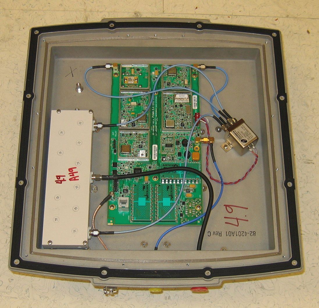
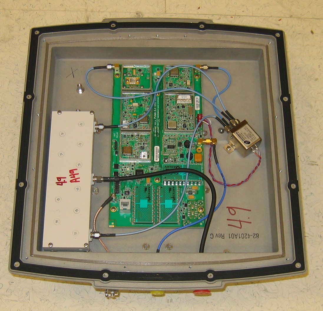
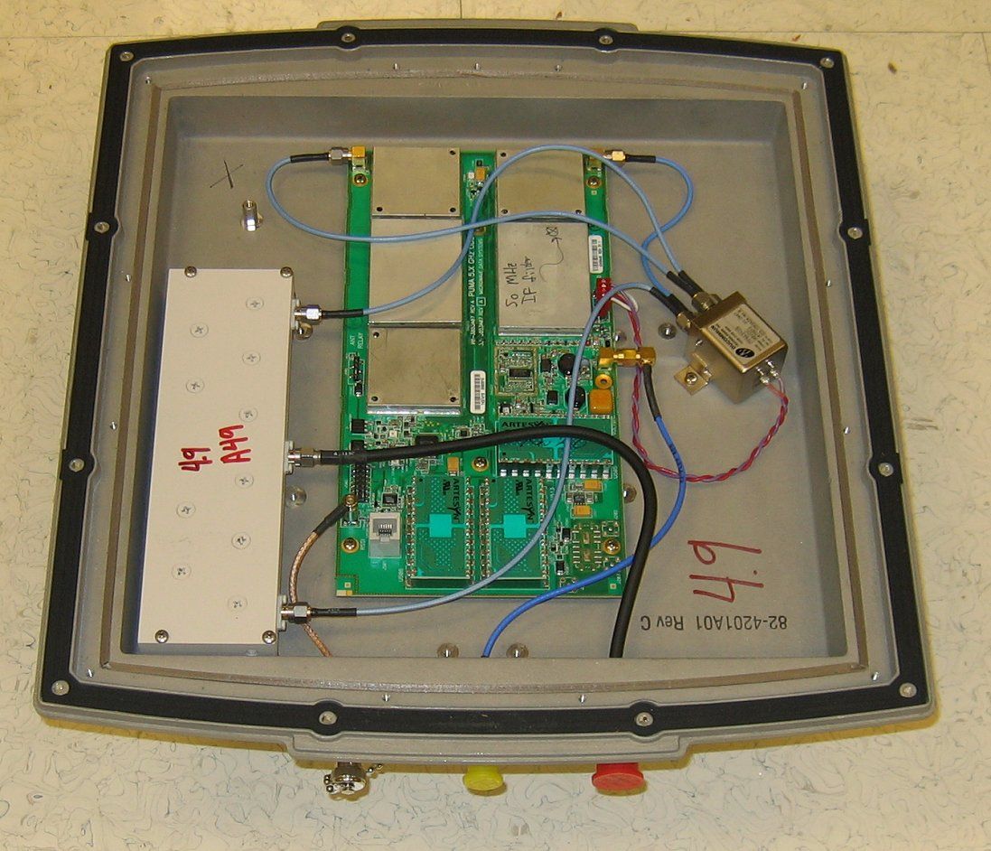
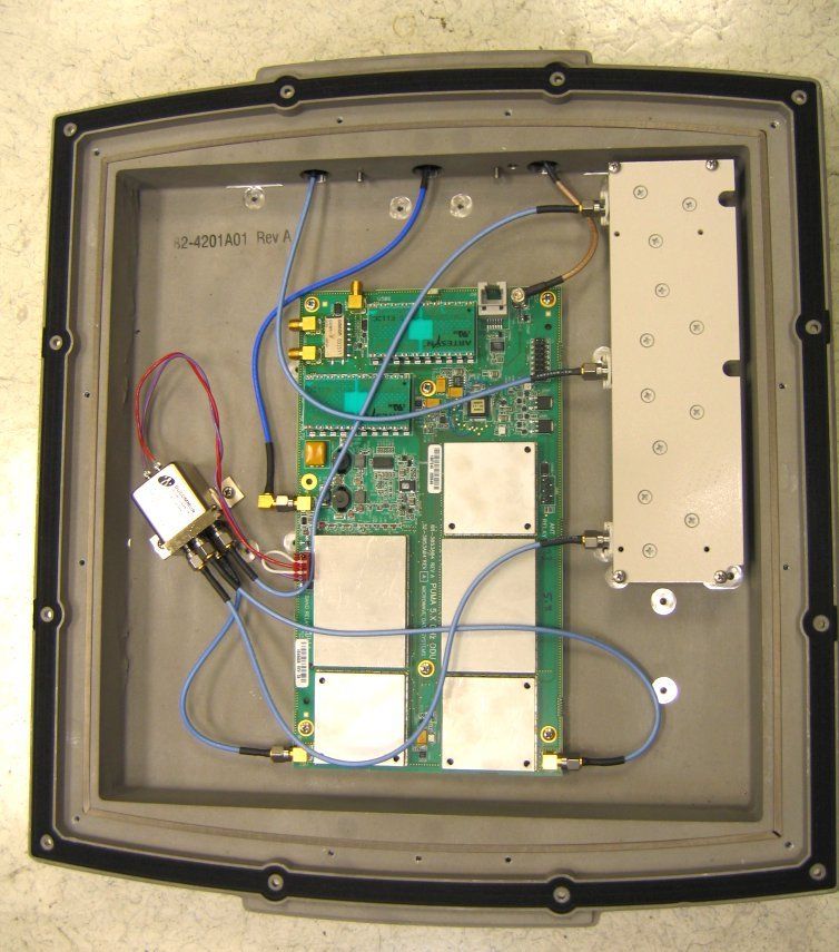
- MDS Four.9 Series Digital Radio System
- Frequency Range
- 4940.00000000 - 4990.00000000
- Company
- GE MDS, LLC
- Country
- United States
Documents & Files
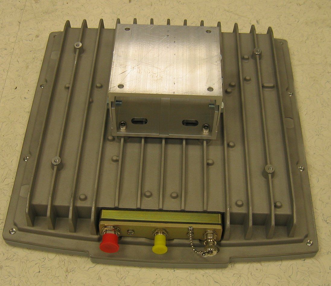
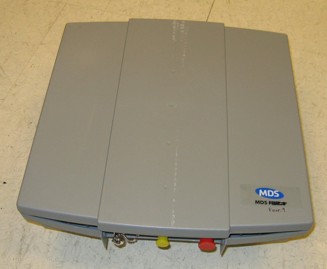
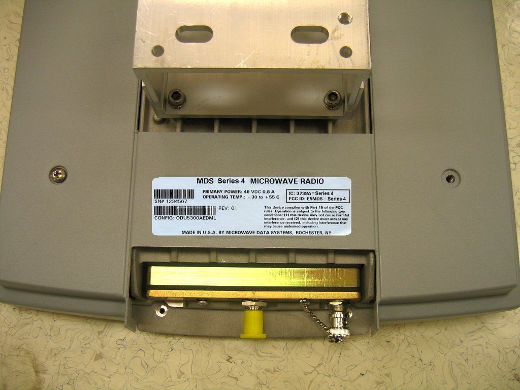
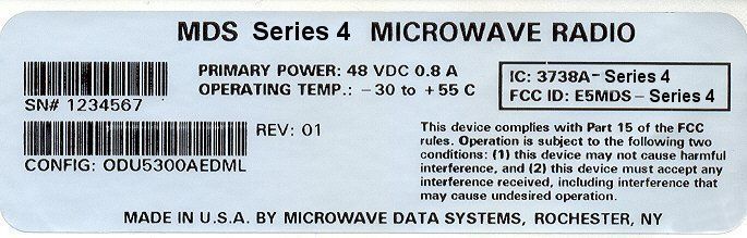
Document Text
Text extracted from the exhibit documents filed with the FCC. Open a document above to read the original.
Users Manual
Microwave Data Systems MDS FOUR.9 Series Digital Radio System User Reference and Installation Guide PRELIMINARY Part No. 05-4561A01, Rev. A Date: 9 JUNE 2006 © 2006 Microwave Data Systems Inc. All Rights Reserved. This book and the information contained herein is the proprietary and confidential information of Microwave Data Systems Inc. that is provided by Microwave Data Systems TM exclusively for evaluating the purchase of Microwave Data Systems Inc. technology and is protected by copyright and trade secret laws. No part of this document may be disclosed, reproduced, or transmitted in any form or by any means, electronic or mechanical, for any purpose without the express written permission of Microwave Data Systems Inc. For permissions, contact Microwave Data Systems Inc. Marketing Group at 1-585-241-5510 or 1-585- 242-8369 (FAX). Notice of Disclaimer The information and specifications provided in this document are subject to change without notice. Microwave Data Systems Inc. reserves the right to make changes in design or components as progress in engineering and manufacturing may warrant. The Warranty(s) that accompany Microwave Data Systems Inc., products are set forth in the sales agreement/contract between Microwave Data Systems Inc. and its customer. Please consult the sales agreement for the terms and conditions of the Warranty(s) proved by Microwave Data Systems Inc. To obtain a copy of the Warranty(s), contact your Microwave Data Systems Inc. Sales Representative at 1-585-241-5510 or 1-585-242-8369 (FAX). The information provided in this Microwave Data Systems Inc., document is provided “as is” without warranty of any kind, either expressed or implied, including, but not limited to, the implied warranties of merchantability, fitness for a particular purpose, or non-infringement. Some jurisdictions do not allow the exclusion of implied warranties, so the above exclusion may not apply to you. In no event shall Microwave Data Systems Inc. be liable for any damages whatsoever – including special, indirect, consequential or incidental damages or damages for loss of profits, revenue, use, or data whether brought in contract or tort, arising out of or connected with any Microwave Data Systems Inc., document or the use, reliance upon or performance of any material contained in or accessed from this Microwave Data Systems Inc. document. Microwave Data Systems’s license agreement may be provided upon request. Additional Terms and Conditions will be finalized upon negotiation or a purchase. The above information shall not be constructed to imply any additional warranties for Microwave Data Systems Inc. equipment including, but not limited to, warranties of merchantability or fitness for an intended use. Trademark Information Software Defined Indoor Unit TM (SDIDU TM ) is a product and trademark of CarrierComm Inc. Java TM is a trademark of Sun Microsystems Inc. Windows® is a registered trademark of Microsoft Corporation All other brand or product names are trademarks or registered trademarks of their respective companies or organizations. Table of Contents 1 SAFETY PRECAUTIONS ......................................................................................................................1-1 2 SYSTEM DESCRIPTION .......................................................................................................................2-1 2.1 About This Manual............................................................................................................................2-1 2.2 Introduction .......................................................................................................................................2-1 2.3 System Features ...............................................................................................................................2-4 2.4 Physical Description ........................................................................................................................2-5 2.4.1 Model Types ................................................................................................................................2-6 2.4.2 Options ........................................................................................................................................2-7 2.4.3 Front Panel Indicators .................................................................................................................2-7 2.4.4 Front Panel Connections .............................................................................................................2-8 2.5 System Description ........................................................................................................................2-12 2.6 Consecutive Point Architecture ....................................................................................................2-15 2.7 2 + 0 (East-West) Configuration ....................................................................................................2-17 2.8 1+1 Protection .................................................................................................................................2-18 2.9 1 + 1 Multi-hop Repeater Configuration .......................................................................................2-19 2.10 Data Interfaces ................................................................................................................................2-21 2.11 Power Management ........................................................................................................................2-21 2.12 MDS FOUR.9 Series Software and Network Management..........................................................2-22 3 INSTALLATION .....................................................................................................................................3-1 3.1 Unpacking......................................................................................................…
Text truncated - open the document above for the full version.
Attestation Statements
July 07, 2006 RE: Microwave Data Systems FCC ID: E5MDS-Series4 1 RF Exposure Exhibit: Exhibit shows hand written calculations intended to demonstrate the minimum safe distance for RF exposure. However calculations are not performed for the worst case EIRP presented in the table. It appears the minimum safe distance should be 90.34 cm, Please confirm and edit the exhibit. Response: That handwritten calculation should be removed from the exhibit and ignored. The correct exposure information is the MPE.pdf file. Sorry for the confusion. 2 Please provide a brief outline of how this minimum safe distance will be maintained once installed. Response: This is a point to point 4.9GHz microwave link data radio, with high data rates of up to 50mbps using a 15MHz bandwidth. This architecture requires a elevated line of sight RF path to maintain a typical signal strength of greater than -80dBm. Thus the safety distance of 1.1 meters will be easy to maintain using a high gain dish antenna mounted on an elevated structure. MDS will use it's trained staff of professional installers and field service personnel to assist in installations and path planning to maintain the optimum RF performance. Thus easily maintaining the 1.1 meter safety distance. User Manual: 3 FCC NOTICE USA: This notice indicates: • The device is a Part 15 device. It is a Part 90 device • Refers to 4.947GHz as being the UNII band in the exposure calculation. 4947MHz is not in the UNII bands. • Includes the FCC part 15 notice. This is not a part 15 device. Response: Manual updated and uploaded for review. 4 SECTION 2.2 INTRODUCTION: • Refers to operating frequencies as being 5./725GHz to 5.85GHz. Please correct • Indicates the UNII band is 4.9GHz, this is incorrect. Response: Manual updated and uploaded for review. 5 SYSTEM FEATURES: • Indicates a Low power setting of 12 dBm. This is below the low power setting level in the test report. Response: Manual updated and uploaded for review. 6 PDF page 18 of the manual refers to 320 mw of RF power. This is higher than any power specified in the test report Response: Manual updated and uploaded for review. 7 PDF Page 38 Operating frequency is specified as being 5.3 or 5.8 GHz Response: Manual updated and uploaded for review. 8 PDF Page 45 The statement on 3.6.5, is incorrect. EIRP is NOT unlimited. Per Part 90.1215 A high power device with a BW of up to 15 MHz has a maximum allowed EIRP of 57.8 dBm. Please remove or reword the manual statement. See rule part below Response: Manual updated and uploaded for review. 9 Please correct or remove paragraph 3.6.6.1 Response: Manual updated and uploaded for review. 10 Table 3.2 refers to antenna gains that are inconsistent with the gains presented in the test report. Additionally this table refers to 30 and 20 MHz bandwidth modes while the 731 form provided indicates bandwidths of 13.7 and 12.5 MHz. Nor do the 20 MHz and 30 MHz mode appear in the test report. Please explain. Response: Manual updated and uploaded for review. 11 There are multiple instances of the 4.9 GHz band being referred to as UNII and additionally multiple instances where 5.8GHa is referred to. (Fig 3.3 for example) Please review. Response: Manual updated and uploaded for review. 12 Please review power levels in the summary specifications. Response: Manual updated and uploaded for review. 13 The manual indicates that this device has “Adaptive Power Control” Please outline how this control limits the maximum power for a given antenna. Eg: How does the APC know what antenna is installed and how does it determine the maximum allowable power setting? Response: Please reference the manual, section 3.6.6.1, where it states the customer enters the maximum power he can transmit. This will be a hard limit the Automatic Power Control cannot over ride, set during setup time of the radio. FYI: RF Safety precautions indicate a minimum safe distance of 119 cm, While this is acceptable, it is inconsistent with the exposure calculations Response: Understood this has been corrected on all appropriate documents. Regards, Juan Martinez Senior EMC Engineer JM/dmg
Cover Letter(s)
175 Science Parkway, Rochester, New York 14620 USA (585) 242-9600 Phone (585) 242-9620 Fax March 27th, 2006 FEDERAL COMMUNICATIONS COMMISSION 7435 Oakland Mills Road Columbia, MD 21046 U.S.A. Subject: Request for withholding from public disclosure the schematic diagrams and system block diagrams pursuant to an application for certification. Applicant: Microwave Data Systems Inc. Product: MDS Series4 point to point microwave radio Model: MDS Series4 FCC ID: E5MDS- Series4 Dear Sir/Madam, We, Microwave Data Systems, would like to request that the schematic diagrams, system block diagram, Theory of Operation and Bill of Materials submitted with the application for certification be withheld from public disclosure as per Section 0.459 of FCC Rules. This request is made under the provisions of Section 0.457(d) of the Commission's Rules, and Section 552(b)(4) of the Freedom of Information Act. These sections authorize as a withholding from public inspection materials which would be privileged as a matter of law if retained by the person submitting them, and materials which would not customarily be released to the public by that person. If you have any queries, please do not hesitate to contact me at 585 242-8440: Yours truly, Dennis McCarthy Agency Compliance Engineer Microwave Data Systems 175 Science Parkway Rochester NY 14620 Phone (585) 242-8440 Email [email protected]
RF Exposure Info
MPE Exposure Formula: S = ( P X G ) / ( 4 X π X d^2 ) where: S = power density P = transmitter conducted power in (mW) G = antenna numeric gain d = distance to radiation center (m) or (.02^2 ) = .020 m 4947.5 MHz Gain =8912.5NumericEUT ant.:39.5dBi Power = 55mWEUT power:17.4dBm Frequency =-MHzMPE limit:5 mW/cm^2 Cable Loss =0dB EIRP =489778.82mW489778.8mW R (cm) = S (20cm) = 4947.5 MHz Gain =4073.8NumericEUT ant.:36.1dBi Power = 148mWEUT power:21.7dBm Frequency =-MHzMPE limit:5 mW/cm^2 Cable Loss =0dB EIRP =602559.59mW602559.6mW R (cm) = S (20cm) = 4947.5 MHz Gain =2041.7NumericEUT ant.:33.1dBi Power = 204mWEUT power:23.1dBm Frequency =-MHzMPE limit:5 mW/cm^2 Cable Loss =0dB EIRP =416869.38mW416869.4mW R (cm) = S (20cm) = Enter Data in Linear Units 97.43888.2897050 Enter Data in Linear Units 97.9287173119.875 Enter Data in Linear Units 81.453559282.934
Test Report
File: R63391 Page 1 of 18 2016-01 Electromagnetic Emissions Test Report In Accordance With FCC Part 90 on the Microwave Data Systems Transmitter Model: MDS Series 4 point to point microwave link FCC ID NUMBER: E5MDS- Series4 GRANTEE: Microwave Data Systems 175 Science Parkway Rochester, NY 14620 TEST SITE: Elliott Laboratories, Inc. 684 W. Maude Avenue Sunnyvale, CA 94086 REPORT DATE: March 27, 2006 FINAL TEST DATE: March 22, 2006 AUTHORIZED SIGNATORY: ______________________________ Juan Martinez Senior EMC Engineer Elliott Laboratories, Inc. is accredited by the A2LA, certificate number 2016-01, to perform the test(s) listed in this report. This report shall not be reproduced, except in its entirety, without the written approval of Elliott Laboratories, Inc. Elliott Laboratories, Inc. -- EMC Department Test Report Report Date: March 27, 2006 File: R63391 Page 2 of 18 pages TABLE OF CONTENTS COVER PAGE............................................................................................................................................................. 1 TABLE OF CONTENTS ............................................................................................................................................ 2 FCC CERTIFICATION INFORMATION ............................................................................................................... 3 DECLARATIONS OF COMPLIANCE .................................................................................................................... 5 SCOPE.......................................................................................................................................................................... 6 OBJECTIVE ................................................................................................................................................................ 6 SUMMARY OF TEST RESULTS ............................................................................................................................. 7 PART 90 TEST SUMMARY....................................................................................................................................... 7 MEASUREMENT UNCERTAINTIES ..................................................................................................................... 8 EQUIPMENT UNDER TEST (EUT) DETAILS ...................................................................................................... 9 GENERAL................................................................................................................................................................ 9 ENCLOSURE ........................................................................................................................................................... 9 MODIFICATIONS ................................................................................................................................................... 9 SUPPORT EQUIPMENT....................................................................................................................................... 10 EUT INTERFACE PORTS .................................................................................................................................... 10 EUT OPERATION DURING TESTING ............................................................................................................... 10 TEST SITE ................................................................................................................................................................. 11 GENERAL INFORMATION ................................................................................................................................. 11 CONDUCTED EMISSIONS CONSIDERATIONS............................................................................................... 11 RADIATED EMISSIONS CONSIDERATIONS................................................................................................... 11 MEASUREMENT INSTRUMENTATION ............................................................................................................ 12 RECEIVER SYSTEM ............................................................................................................................................ 12 INSTRUMENT CONTROL COMPUTER ............................................................................................................ 12 PEAK POWER METER ........................................................................................................................................ 12 FILTERS/ATTENUATORS................................................................................................................................... 12 ANTENNAS ........................................................................................................................................................... 13 ANTENNA MAST AND EQUIPMENT TURNTABLE ....................................................................................... 13 INSTRUMENT CALIBRATION........................................................................................................................... 13 TEST PROCEDURES............................................................................................................................................... 14 SPECIFICATION LIMITS AND SAMPLE CALCULATIONS .......................................................................... 18 RADIATED EMISSIONS SPECIFICATION LIMITS.......................................................................................... 18 CALCULATIONS – EFFECTIVE RADIATED POWER ..................................................................................... 18 EXHIBIT 1: Test Equipment Calibration Data .................................................................................................... 1 EXHIBIT 2: Test Data Log Sheets ...................................................…
Text truncated - open the document above for the full version.
Contact Information
Applicant
John Barenys(Senior Operations Manager)
Technical Contact
Elliott LabortoriesJuan Martinez
[email protected]408 245 7800
684 W Maude Ave · Sunnyvale, California · United States
Test Firm
Elliott Laboratories Inc.David Bare
Technical Specifications
| # | Rule Parts | Frequency Range | Power Output | Emission | Tolerance |
|---|---|---|---|---|---|
| 1 | 90 | 4.94 GHz - 4.99 GHz | 204.10 mW | 13M7X1D | 0.4000000000 ppm |
Other Applications from GE MDS, LLC

E5MDS-NET9S
Jul 13, 2023Frequency Hopping Radio
Equipment Class
DSS - Part 15 Spread Spectrum Transmitter
E5MDS-NET9L
Jul 11, 2023Frequency Hopping Radio
Equipment Class
DSS - Part 15 Spread Spectrum Transmitter
E5MDS-LN900
Jan 27, 2016Industrial Radio Module
Equipment Class
TNB - Licensed Non-Broadcast Station Transmitter
E5MDS-SDM4
Aug 20, 2015MDS SDM4 Licensed Spectrum Module
Equipment Class
TNB - Licensed Non-Broadcast Station Transmitter
E5MDS-LN400
Jul 09, 2015Industrial Radio Module
Equipment Class
TNB - Licensed Non-Broadcast Station Transmitter