E5MDS-SF9Wireless Data Transceiver Module
GE MDS, LLC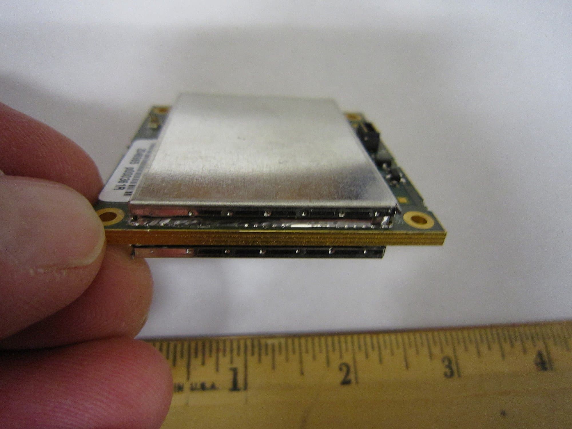
Click to zoom
Application Details
- Equipment Class
- DSS - Part 15 Spread Spectrum Transmitter
- Date of Grant
- Mar 20, 2011
- Application Purpose
- Original Equipment
- Date of Application
- Mar 20, 2011
- Equipment Note
- Wireless Data Transceiver Module
- Frequency Range
- 902.20000000 - 927.60000000
- Company
- GE MDS, LLC
- Country
- United States
Documents & Files
Document Text
Text extracted from the exhibit documents filed with the FCC. Open a document above to read the original.
Users Manual
1.0INTRODUCTION 05-6334A01, Rev. AMDS SF9 Integration Guide1 MDS TransNET-SF9 Publication No. 05-6334A01, Rev. 01 The MDS TransNET-SF9 (Figure 1), is a modular spread spectrum transceiver designed for use in the license-free 902-928 MHz band. The unit is designed for use inside data equipment to provide reliable connectivity in wireless networks. The SF9 employs a closed-loop power control circuit, ensuring that th e RF output never exceeds +30 dBm at the antenna connector. The module is designed for OEM use only. Host systems, if used with antennas having standard connectors, must be professionally installed. Host systems using integrated antennas or unique antenna connectors must be factory configured by the OEM to operate at the correct output power setting. Refer to the table at the end of this guide to determine applicable antenna types and the RF output power allowed. Electronic copies of this document and othe r GE MDS user guides are available free of charge at www.gemds.com. 1.1Transceiver Features The SF-9 maximizes performance and flexibility in wireless networks, offering the following key features: • 128 frequencies over 902–928 MHz, divided into 8 zones • User-selectable option to skip sub-bands with interference • 65,000 available network addresses • Network-wide configuration from the Master station, elimi- nating most trips to Remote sites • Data transparency ensures compatibility with virtually all asynchronous SCADA system terminals. • Peak-hold RSSI averaged over eight hop cycles • Operation at up to 115,200 bps continuous data flow • Store-and-Forward repeater operation • Data latency typically less than 10 ms • Same hardware for Master or Remote configuration • Supports RS/EIA-232 and RS/EIA-485 user interface • Low current draw; typically less than 8 mA in sleep mode • Operates at 3.3 Vdc at the power connector Figure 1. SF9 Transceiver Module (J3 Data/Power and J200 Antenna Connectors on other side) NOTE:Some features may not be available on all units, based on the options purchased, or regulatory constraints in the country of operation. 1.2Accessories GE MDS offers an Accessories Selection Guide listing additional items that may be used with our products. Contact your factory representative or visit www.gemds.com for the latest copy. 2.0INSTALLATION The transceiver is designed for installation in existing electronic equipment. It mounts to any flat surface using screws through the four holes provided in the corners of the PC board. Only two cable connections required to the radio; J3, the Powe r/Data connector, and J200, the Antenna connector. It is recommended that the module be installed in a manner that permits viewing the four status LEDs (CR3, 4, 5, and 6) during operation. These LEDs provide important information that is useful during startup and optimization of the radio link. Antennas used with the radio can be either a Yagi directional type (ofte n used at remote sites) or an omni-directional type used for short range applications or at Master stations. Contact your sales representative for information on available antennas. Follow these steps to install the transceiver module: 1. Select a suitable mounting location for the module. This sho uld be a flat surface close enough to the power/data and antenna cabling so that these will reach their respective connectors. 2. Secure the module to the surface using suitable screws throu gh the mounting holes in each corner of the radio’s PC board. Use spacers as necessary to achieve required height. (Mounting hardware is not supplied.) 3. Select and install an appropriate antenna and feedline for your system coverage requirement s. 4. Connect the antenna coaxial lead to J200 on the module. It a ccepts a Type-UMC female coaxial connector. 5. Prepare the power/data cabling for connection to J3 on the mod ule. It accepts a Molex SlimStack TM 20 pin receptacle. Use only the required data pins for the application (see Table 1 for pin information). The input power applied to J3 must be 3.3 Vdc (-0/+0 .2 V). Connect the plug to J3. Table 1: J3 Power/Data Connector Pinouts Pin(s)Description 1, 2, 7, 8Signal Ground—Connects to ground (negative supply potential) on the radio’s PC board and chassis 3, 4, 5, 63.3 Vdc Input 9Alarm 10DCD_LED 11Serial Configuration 12CTS (Clear-to-Send)—Goes “high” after the programmed CTS delay time has elapsed (DCE), or keys an attached radio when RF data arrives (CTS KEY). CTS_N-485_DE 13RXD (Received Data)—Supplies received data to the connected device 14RTS (Request-to-Send) 15TXD (Transmitted Data)— Accepts TX data from the connected device 16Power Supply Shutdown PS_SHDN 17Sleep 18DIAG_RXD 19DIAG_TXD 20Reserved. Do not connect. 2MDS SF9 Integration Guide05-6334A01, Rev. A 6. Set the radio’s basic configuration with a PC terminal con- nected to J3. The three essential settings for all transceivers are: •Mode: Master, Remote, or Extension •Network Address: A unique number from 1 to 65000 •Data Interface Parameters: bps, data bits, parity, stop bits 7. Observe the transceiver LED status p anel for proper indica- tions (see Table 2). Table 2: LED Indicator Descriptions LED NameDescription RXD (CR 3) Receive Data Serial receive data activity. Payload data from connected device. TXD (C R4) Transmit Data Serial transmit data activity. Payload data to connected device. DCD (C R5) Data Carrier Detect Continuous—Radio is receiving/sending syn- chronization frames On within 10 seconds of power-up under nor- mal conditions GP (C R6) General Purpose • Continuous—Power is applied to the radio; no pr oblems detected • Flashing (5 times-per-second)—Fault indi- cation. See Tr oubleshooting • Off—Radio is unpowered or in Sleep mode 8. In a normally operating system, you will see the following indi- cations within 16 seconds of start-up: •PWR lamp lit continuously •SYNC lamp lit continu ously • Remote radio(s) transmitting data (TXD) and recei ving data (RXD) with the Master station. 9. Optimize the in…
Text truncated - open the document above for the full version.
Cover Letter(s)
Page 1 of 1 Elliott TCB 41039 Boyce Raod Fremont, CA, 94538 To whom it may concern: The enclosed documents constitute a formal submittal and application for Equipment Authorization for a Frequency Hopping Spread Spectrum radio module pursuant to the following rules: Subpart C of Part 15 of FCC Rules (CFR 47) RSS-Gen Issue 3, December 2010, “General Requirements and Information for the Certification of Radiocommunication Equipment” RSS-210, Issue 8, December 2010, “Low-power Licence-exempt Radiocommunication Devices (All Frequency Bands): Category I Equipment” This module is limited to professional installation using monopole antennas with gains up to 7dBd and Yagi antennas with gains up to 10dBd. Elliott Laboratories, as duly authorized agent prepared this submittal. A copy of the letter of our appointment as agent is included with the application. If there are any questions or if further information is needed, please contact Elliott Laboratories for assistance. Sincerely, David W. Bare Chief Engineer
Cover Letter(s)
175 Science Parkway, Rochester, New York 14620 USA (585) 242-9600 Phone (585) 242-9620 Fax Jan 27th, 2011 FEDERAL COMMUNICATIONS COMMISSION 7435 Oakland Mills Road Columbia, MD 21046 U.S.A. Subject: Authority to Act as an Agent to FCC & IC (Industry Canada) Applicant: GE MDS LLC. Product: SF9 FCC ID: E5MDS-SF9 Elliott TCB 684 West Maude Ave. Sunnyvale, CA. 94085 Gentlemen: This is your letter of authorization to accept our appointment of Elliott Laboratories LLC as our Agent for GE MDS LLC, to sign applications before Elliott TCB and to make representations to you on our behalf. Elliott Laboratories LLC is to receive and exchange data between our company and Elliott TCB. I hereby certify on behalf of GE MDS LLC ("Applicant") that neither Applicant nor any party to the application (officers, directors, and 5% shareholders) is subject to a denial of Federal benefits that includes FCC benefits pursuant to section 5301 of the Anti-Drug Abuse Act of 1988. 21 U.S.C. 853a. Sincerely, Dennis McCarthy If you have any queries, please do not hesitate to contact me at 585 242-8440: Yours truly, Dennis W McCarthy T +1 (585) 242-8440 Agency Compliance Engineer E [email protected] GE Digital Energy – MDS
Cover Letter(s)
GS MDS SF9 Limited Modular Approval Requirements Limited Modular Approval is being requested for this device and the device will be installed only in host systems manufactured by GE MDS professional installers. Limited Modular Approval is being requested for this device. There are requirements that the device must meet for Limited modular approval. The following paragraphs detail those requirements and explains, where applicable, how the module meets those requirements. Where requirements are not met a justification for a limited modular approval is presented. The module meets all of the technical specifications applicable to the frequency band of operation. 1. The module has its own RF shielding (RSS GEN 3.2.2a). The radio module is fully shielded both top and bottom of the PCB 2. All modulation and data input(s) are buffered (RSS GEN 3.2.2b). All Data modulation is buffered via U102 a DSP (DSP56F807) 3. The module has its own power supply regulation (RSS GEN 3.2.2c).and local reference oscillator. This module does not contain on board regulation, the OEM integrator will supply, 3.3vdc to the radio module. OEM Integrators must regulate the DC voltage applied to the SF9 module at +3.3 Vdc, with a tolerance of -.0/+.2 Vdc. This can be achieved using a voltage regulator similar to the Texas Instruments PTH0407W, which is a precision DC regulator. This was the regulator used for all certification testing. The reference oscillator is on the PCB, Y1 a 16MHz TXCO, a 10.7 MHz discriminator in U201 and a onboard VCO based on Q301 4. The modular transmitter must comply with the antenna requirements of Section 15.203 and 15.204(c). The certification submission contains a detailed description of the configuration of all antennas that will be used with the module. (RSS GEN 3.2.2d). Limited Modular Approval requires the OEM professional installation for this application. A list of allowed antenna’s is supplied in the FCC test report. 5. The modular transmitter must be tested in a stand-alone configuration, i.e., the module must not be inside another device during testing (RSS GEN 3.2.2e). This is intended to demonstrate that the module is capable of complying with Part 15 emission limits regardless of the device into which it is eventually installed. Unless the transmitter module will be battery powered, it must comply with the AC line conducted requirements found in Section 15.207. Test data contained in this application is for the device tested in a stand-alone configuration. Radiated spurious emissions data and AC conducted emissions data demonstrating compliance with the requirements of Part 15 of the FCC rules for intentional radiators and RSS GEN/RSS 210 has been provided. 6. For the FCC, the modular transmitter must be labeled with its own FCC ID number, and, if the FCC ID is not visible when the module is installed inside another device, then the outside of the device into which the module is installed must also display a label referring to the enclosed module. This exterior label can use wording such as the following: “Contains Transmitter Module FCC ID: XYZMODEL1” or “Contains FCC ID: XYZMODEL1.” The module is appropriately labeled (refer to the label and label location drawings contained within this application). Instructions to the end user regarding the labeling requirements for host devices are included in this application. 7. For Industry Canada, the module shall comply with the Category I equipment labelling requirements. (RSS GEN 3.2.2f). The module is appropriately labeled (refer to the label and label location drawings contained within this application). 8. The modular transmitter must comply with any applicable RF exposure requirements. The module meets the requirements for a portable device that may be used at separation distances of less than 2.5cm from the human body because its output power is below the threshold of 60/f GHz mW (25mW for a 2.4GHz device). OR The module meets the requirements for a mobile device that may be used at separation distances of more than 20cm from the human body. Refer to the MPE calculation. 9. (RSS GEN 3.2.1) The host device shall be properly labelled to identify the modules within the host device. The Industry Canada certification label of a module shall be clearly visible at all times when installed in the host device, otherwise the host device must be labelled to display the Industry Canada certification number of the module, preceded by the words “Contains transmitter module”, or the word “Contains”, or similar wording expressing the same meaning, as follows: Contains transmitter module IC: XXXXXX-YYYYYYYYYYY where XXXXXX-YYYYYYYYYYY is the module’s certification number. The applicant for equipment certification of the module shall provide with each unit of the module either a label such as described above, or an explanation and instructions to the user as to the host device labelling requirements. Instructions to the end user regarding the labeling requirements for host devices are included in this application.. RSS GEN Checklist Modular approval requirement Yes No * (a) The radio elements must have the radio frequency circuitry must be shielded. Physical/discrete and tuning capacitors may be located external to the shield, but must be on the module assembly. √ X (b) The module shall have buffered modulation/data input(s) (if such inputs are provided) to ensure that the module will comply with the requirements set out in the applicable RSS standard under conditions of excessive data rates or over-modulation. √ X (c) The module shall have its own power supply regulation on the module. This is to ensure that the module will comply with the requirements set out in the applicable standard regardless of the design of the power supplying circuitry in the host device which houses the module. X √ (d) The module shall comply with the provisions for external power amplifiers and antennas detailed in this standard. The equipment certification submission …
Text truncated - open the document above for the full version.
Cover Letter(s)
175 Science Parkway, Rochester, New York 14620 USA (585) 242-9600 Phone (585) 242-9620 Fax Jan 31st, 2011 FEDERAL COMMUNICATIONS COMMISSION 7435 Oakland Mills Road Columbia, MD 21046 U.S.A. Subject: Limited Modular approval request, & Professional Installation Applicant: GE MDS LLC. Product: MDS SF9 FCC ID: E5MDS-SF9 Professional Installation The Transnet‐SF9 radio must be professionally (OEM) installed and thus is exempt from the antenna restrictions of FCC Part 15.203. OEM Integrators must regulate the DC voltage applied to the SF9 module at +3.3 Vdc, with a tolerance of ‐.0/+.2 Vdc. This can be achieved using a voltage regulator similar to the Texas Instruments PTH0407W, which is a precision DC regulator.” The Transnet‐SF9 is not designed for use by the general public, and will be sold through the GE MDS sales force to OEM systems integrators. These companies will either use their professional telecommunications engineering staff to carry out the installation or will subcontract to professional installation firms. Due to the unique technical expertise required in installing and setting up the system, the product is not suitable for distribution to retail channels. In spite of this, GE MDS will warn integrators against selling to retail channels in compliance to FCC regulations. The Transnet‐SF9 radio will be OEM integrated into systems used for fixed, permanent or temporary, outdoor environment. The equipment and their antennas will need professional installers to mount and setup. The output power and cable feed loss for an installation of the Transnet‐SF9 radio will be set to meet the applicable EIRP limits by the professional installer during installation. The method of adjusting the output power is described in the integrators instructions for incorporation in their end product manual for use by professionally trained installers. The Transnet‐SF9 radio is sold without an antenna and the customer and/or installation engineer chooses from commercially available antennas in the approved antenna scope. The professional installation engineer is responsible to install only those commercially available antenna(s) (or similar) as listed in the filing. From time to time, GE MDS may sell a commercially available antenna as listed in the filing along with the Transnet‐SF9 radio upon customer request and the instruction remind the integrator that only antenna(s) covered in the filing are to be used with the device. GE MDS has also included detailed instructions on how to determine the maximum output power based on EIRP limits for all professional installers to follow. GE MDS LLC is also requesting that FCC ID E5MDS‐SF9 is granted the LMA Limited Modular Approval. None of MDS’s products are for sale to the general public, and are for Industrial applications only, examples, SCADA applications, traffic control, flow rate applications. Thus MDS has a trained staff of technical personnel that work with our industrial customers to ensure “professional installation” is achieved. In all cases the FCC EIRP limits are maintained. When the Limited Modular approval is granted, MDS will perform training on it’s staff, inform them of the “Limited Modular Approval” requirements, and list the technical differences between “Modular and LMA”, to ensure it’s staff keep the installations in compliance. All the FCC module testing was performed with antennas that we currently are going to offer for professional installation of this product. The antenna and cable interfaces, are a NON standard “UMC” connectors, and the cable interconnects do fulfill the FCC’s Modular requirements. All the antennas that will be used with the Professional installation grant, will be installed by trained/qualified personnel to ensure the strictest compliance with FCC rules. All supporting manuals and sales literature reflect the regulatory issues. The following text will be placed in the SF9 installation and user manual, and is being “requested” on the FCC grant. We support this wording on the actual FCC grant and will follow these restrictions “Power listed is conducted. The module may only be installed in professionally installed hosts systems containing the appropriate voltage regulation circuitry and marketed by the OEM detailed in the filing. Marketing to the general public is prohibited. The antenna installation and operating configurations of this transmitter, including antenna gain and cable loss must be in accordance with configurations described in this filing. The antennas used for this transmitter must be installed to provide a separation distance of at least 23 cm from all persons and must not be co- located or operating in conjunction with any other antenna or transmitter, except in accordance with FCC multi- transmitter product procedures. End -users and installers must be provided with antenna installation instructions and transmitter operating conditions for satisfying RF exposure compliance. If you have any queries, please do not hesitate to contact me at 585 242-8440: Yours truly, Dennis W McCarthy T +1 (585) 242‐8440 Agency Compliance Engineer E [email protected] GE Digital Energy – MDS
Cover Letter(s)
175 Science Parkway, Rochester, New York 14620 USA (585) 242-9600 Phone (585) 242-9620 Fax March 11th, 2011 FEDERAL COMMUNICATIONS COMMISSION 7435 Oakland Mills Road Columbia, MD 21046 U.S.A. Subject: OEM Integration for the SF9 LMA module Applicant: GE MDS LLC. Product: SF9 Model: MDS SF9 FCC ID: E5MDS-SF9 Dear Sir/Madam, The SF9 design was undertaken for a specific customer, “E-PRODUCTIONS”, they are one of our OEM large customers. http://www.ep-solutions.com/ E-productions funded the development of the SF9 module. The module form fit and function were supplied to GE MDS. We were required to meet their dimensions and interfaces. They will supply DC to the module from the exact circuit that was placed in the manual. The regulator schematic was supplied by our customer, this is exactly how it the unit will be used. When the transmitter module is operating with 3.3vdc, there is a “closed loop RF power control” that uses a precision RF detector and “AtoD” converter to maintain the transmitter power with the respective PWR setting chosen, this will operate from +20 to +30dBm, 1dB increments. High gain antenna’s were tested at Elliott labs using this closed loop power RF power control thus maintaining the +36dBm ERP limits. If the voltage dips below or above +3.3vdc the “FWD PWR” control compensates to maintain the programmed RF level. This module will only be sold to the customer E-Productions. If you have any queries, please do not hesitate to contact me at 585 242-8440: Yours truly, Dennis McCarthy Agency Compliance Engineer GE MDS LLC 175 Science Parkway Rochester NY 14620 Phone (585) 242-8440 Email [email protected]
Cover Letter(s)
175 Science Parkway, Rochester, New York 14620 USA (585) 242-9600 Phone (585) 242-9620 Fax Sept 8th, 2014 FEDERAL COMMUNICATIONS COMMISSION 7435 Oakland Mills Road Columbia, MD 21046 U.S.A. Subject: Request for withholding from public disclosure the schematic diagrams, Software Specification and system block diagrams pursuant to an application for certification. Applicant: GE MDS LLC. Product: SF9 FCC ID: E5MDS-SF9 Dear Sir/Madam, Somehow the “CONFIDENTIAL Software Specification” was uploaded for the FCC submission of the SF9 product back in 2011 and listed under the “User Manual”. We need to remove this specification from the public side of the FCC grant filing. We are aware that this information has been publicly available since the date the grant was issued. However this information is confidential and needs to be removed. We, GE MDS LLC, would like to request that the schematic diagrams, system block diagram, Theory of Operation and Software specification submitted with the initial application for certification be withheld from public disclosure as per Section 0.459 of FCC Rules. This request is made under the provisions of Section 0.457(d) of the Commission's Rules, and Section 552(b)(4) of the Freedom of Information Act. These sections authorize as a withholding from public inspection materials which would be privileged as a matter of law if retained by the person submitting them, and materials which would not customarily be released to the public by that person. If you have any queries, please do not hesitate to contact me at 585 242-8440: Yours truly, Dennis McCarthy Agency Compliance Engineer GE MDS LLC 175 Science Parkway Rochester NY 14620 Phone (585) 242-8440, Email [email protected]
RF Exposure Info
EMC Test Data Client: Contact: Standard: Test Specific Details General Test Configuration No 22.7 Modifications Made During Testing No modifications were made to the EUT during testing Deviations From The Standard No deviations were made from the requirements of the standard. Calculation uses the free space transmission formula: S = (PG)/(4 πd 2 ) Where: S is power density (W/m 2 ), P is output power (W), G is antenna gain relative to isotropic, d is separation distance from the transmitting antenna (m). Summary of Results Device complies with Power Density requirements at 20cm separation: If not, required separation distance (in cm): Test Engineer: David Bare Maximum Permissible Exposure Objective: Evaluate the RF Exposure requirements per FCC 1.1310, 2.1091 and RSS-102. Date of Test: 1/27/2011 Dennis McCarthy FCC 15.247, RSS-210Class: N/ A GE MDS LLCJob Number: J79098 Model: Transnet-SF9 T-Log Number: T79794 Account Manager: Susan Pelzl T79794 GE MDS.xlsMPE CalculationPage 1 of 3 EMC Test Data Client: Contact: Standard: Dennis McCarthy FCC 15.247, RSS-210Class: N/ A GE MDS LLCJob Number: J79098 Model: Transnet-SF9 T-Log Number: T79794 Account Manager: Susan Pelzl Use: General Antenna:12.2 dBi FOR 300-1500 MHz sin gle transmitters Cable AntPower Freq.LossGainat AntEIRP MHzdBmmW*dBdBidBmmW 902.223.7234.4012.223.73890.45 91523.7234.4012.223.73890.45 927.623.5223.9012.223.53715.35 For the cases where S > the MPE Limit Fre q. MHz 902.2 915 927.6 Use: General Antenna:9.2 dBi FOR 300-1500 MHz sin gle transmitters Cable AntPower Freq.LossGainat AntEIRP MHzdBmmW*dBdBidBmmW 902.226.7467.709.226.73890.45 91526.7467.709.226.73890.45 927.626.5446.709.226.53715.35 For the cases where S > the MPE Limit Fre q. MHz 902.2 915 927.6 0.7390.61821.9 0.7740.61022.5 0.7740.60122.7 at 20 cmat 20 cmS <= MPE Limit mW/cm^2mW/cm^2cm Power Density (S)MPE LimitDistance where Powe r 0.7740.601 0.774 at 20 cmat 20 cm mW/cm^2mW/cm^2 0.610 0.7390.618 Power Density (S)MPE Limit 0.7390.61821.9 EUT 0.7740.61022.5 0.7740.60122.7 mW/cm^2mW/cm^2cm at 20 cmat 20 cmS <= MPE Limit Power Density (S)MPE LimitDistance where 0.7740.610 0.7390.618 mW/cm^2mW/cm^2 0.7740.601 EUTPower Density (S)MPE Limit Powe rat 20 cmat 20 cm T79794 GE MDS.xlsMPE CalculationPage 2 of 3 EMC Test Data Client: Contact: Standard: Dennis McCarthy FCC 15.247, RSS-210Class: N/ A GE MDS LLCJob Number: J79098 Model: Transnet-SF9 T-Log Number: T79794 Account Manager: Susan Pelzl Use: General Antenna:6 dBi FOR 300-1500 MHz sin gle transmitters Cable AntPower Freq.LossGainat AntEIRP MHzdBmmW*dBdBidBmmW 902.229.7933.30629.73715.35 91529.7933.30629.73715.35 927.629.6912.00629.63630.78 For the cases where S > the MPE Limit Fre q. MHz 902.2 915 927.6 0.7390.60122.2 0.7220.61821.6 at 20 cmat 20 cmS <= MPE Limit 0.7390.61022.0 0.7390.610 0.7220.618 0.739 mW/cm^2mW/cm^2cm Power Density (S) at 20 cmat 20 cm mW/cm^2mW/cm^2 MPE LimitDistance where 0.601 EUTPower Density (S)MPE Limit Powe r T79794 GE MDS.xlsMPE CalculationPage 3 of 3
Test Report
File: R81914 Page 1 of 22 EMC Test Report Application for Grant of Equipment Authorization Industry Canada RSS-Gen Issue 3 / RSS 210 Issue 8 FCC Part 15 Subpart C Model: Transnet-SF9 IC CERTIFICATION #: 101D-SF9 FCC ID: E5MDS-SF9 APPLICANT: GE MDS LLC 175 Science Parkway Rochester, NY 14620 TEST SITE(S): Elliott Laboratories 41039 Boyce Road. Fremont, CA. 94538-2435 IC SITE REGISTRATION #: 2845B-3; 2845B-4, 2845B-5, 2845B-7 REPORT DATE: February 25, 2011 FINAL TEST DATES: June 28 and 30 and December 8, 2010 and January 18, 19, 20 and 24, 2011 AUTHORIZED SIGNATORY: ______________________________ David W. Bare Chief Engineer Elliott Laboratories Elliott Laboratories is accredited by the A2LA, certificate number 2016-01, to perform the test(s) listed in this report, except where noted otherwise. This report shall not be reproduced, except in its entirety, without the written approval of Elliott Laboratories Elliott Laboratories -- EMC Department Test Report Report Date: February 25, 2011 File: R81914 Page 2 of 22 REVISION HISTORY Rev# Date Comments Modified By - 02-25-2011 First release Elliott Laboratories -- EMC Department Test Report Report Date: February 25, 2011 File: R81914 Page 3 of 22 TABLE OF CONTENTS REVISION HISTORY .............................................................................................................................................. 2 TABLE OF CONTENTS .......................................................................................................................................... 3 SCOPE........................................................................................................................................................................ 4 OBJECTIVE .............................................................................................................................................................. 4 STATEMENT OF COMPLIANCE......................................................................................................................... 5 DEVIATIONS FROM THE STANDARDS ............................................................................................................ 5 TEST RESULTS SUMMARY ................................................................................................................................. 6 FREQUENCY HOPPING SPREAD SPECTRUM (902 – 928 MHZ, 50 CHANNELS OR MORE) ........................ 6 GENERAL REQUIREMENTS APPLICABLE TO ALL BANDS........................................................................ 7 MEASUREMENT UNCERTAINTIES..................................................................................................................8 EQUIPMENT UNDER TEST (EUT) DETAILS .................................................................................................... 9 GENERAL.............................................................................................................................................................. 9 OTHER EUT DETAILS......................................................................................................................................... 9 ANTENNA SYSTEM ............................................................................................................................................ 9 ENCLOSURE......................................................................................................................................................... 9 MODIFICATIONS................................................................................................................................................. 9 SUPPORT EQUIPMENT....................................................................................................................................... 9 EUT INTERFACE PORTS .................................................................................................................................. 10 EUT OPERATION ............................................................................................................................................... 10 TEST SITE............................................................................................................…
Text truncated - open the document above for the full version.
Contact Information
Applicant
John Barenys(Senior Operations Manager)
Test Firm
NTS Labs, LLC Fremont & NewarkDavid Bare
Technical Specifications
| # | Rule Parts | Frequency Range | Power Output |
|---|---|---|---|
| 1 | 15C | 902.2 MHz - 927.6 MHz | 933.00 mW |
Other Applications from GE MDS, LLC

E5MDS-NET9S
Jul 13, 2023Frequency Hopping Radio
Equipment Class
DSS - Part 15 Spread Spectrum Transmitter
E5MDS-NET9L
Jul 11, 2023Frequency Hopping Radio
Equipment Class
DSS - Part 15 Spread Spectrum Transmitter
E5MDS-LN900
Jan 27, 2016Industrial Radio Module
Equipment Class
TNB - Licensed Non-Broadcast Station Transmitter
E5MDS-SDM4
Aug 20, 2015MDS SDM4 Licensed Spectrum Module
Equipment Class
TNB - Licensed Non-Broadcast Station Transmitter
E5MDS-LN400
Jul 09, 2015Industrial Radio Module
Equipment Class
TNB - Licensed Non-Broadcast Station Transmitter