E5MDS-TRM220SBTRM220SB
GE MDS, LLC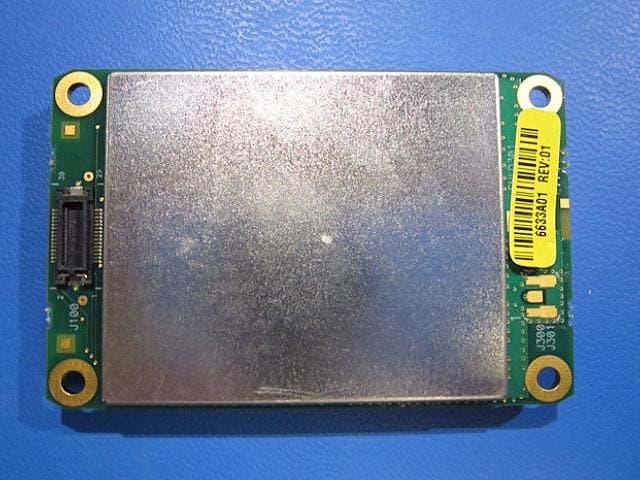
Click to zoom
Application Details
- Equipment Class
- TNB - Licensed Non-Broadcast Station Transmitter
- Date of Grant
- Jun 12, 2012
- Application Purpose
- Original Equipment
- Date of Application
- Jun 12, 2012
- Equipment Note
- TRM220SB
- Frequency Range
- 220.00000000 - 222.00000000
- Company
- GE MDS, LLC
- Country
- United States
Documents & Files
Document Text
Text extracted from the exhibit documents filed with the FCC. Open a document above to read the original.
Users Manual
Integration Guide 216–235 MHz Data Transceivers TRM SB OEM Series MDS 05-4121A03, Rev. A MAY 2012 MDS 05-4121A03, Rev. ATRM SB Integration Guidei TABLE OF CONTENTS 1.0 INTRODUCTION ......................................................................... 7 1.1 Modem Speed versus Channel Bandwidth ...................................... 8 1.2 Frequency Coverage ........................................................................ 8 1.3 Radio Operating Modes ................................................................... 8 Single Frequency (Simplex) Operation ............................................... 8 Switched-Carrier Operation (Half-Duplex) .......................................... 8 Receive Only Operation...................................................................... 9 1.4 Applications ...................................................................................... 9 Point-to-Multipoint, Multiple Address Systems (MAS) ........................ 9 Point-to-Point System ....................................................................... 10 1.5 Model Number Codes .................................................................... 11 2.0 INSTALLATION DESIGN ........................................................... 12 2.1 Mounting the Transceiver ............................................................... 13 2.2 Interface Requirements .................................................................. 13 2.3 Antennas and Feedlines ................................................................ 14 Antennas .......................................................................................... 14 Feedlines .......................................................................................... 15 2.4 Primary Power (3.6 Vdc) ................................................................ 15 DC Supply Connection ..................................................................... 15 Shutdown Mode (Energy Conservation)........................................... 16 2.5 Data Interface Connections ............................................................ 16 3.0 TRANSCEIVER CONFIGURATION AND DIAGNOSTIC COMMANDS ..................................................................................... 19 3.1 Error Messages .............................................................................. 21 3.2 Initial Installation—Radio and Data Configuration .......................... 22 4.0 TROUBLESHOOTING ............................................................... 23 5.0 TECHNICAL REFERENCE ....................................................... 24 5.1 Transceiver Specifications .............................................................. 24 5.2 Test and Evaluation Assembly ....................................................... 25 5.3 Vendors for Connectors .................................................................. 28 5.4 dBm-Watts-Volts Conversion Chart ................................................ 29 6.0 GLOSSARY OF TERMS............................................................ 30 iiTRM SB Integration GuideMDS 05-4121A03, Rev. A Copyright Notice This Installation and Operation Guide and all software described herein are protected by copyright: 2012 GE MDS . All rights reserved. GE MDS reserves its right to correct any errors and omissions in this publication. Antenna Installation Warning 1. All antenna installation and servicing is to be performed by qualified technical personnel only. When servicing the antenna, or working at distances closer than those listed below, ensure the transmitter has been disabled. 2. The radio equipment described in this guide emits radio frequency energy. Although the power level is low, the concentrated energy from a directional antenna may pose a health hazard. Do not allow people to come closer than 1.4 meters to the front of the antenna when the transmitter is operating with a 11.85 dBd (14 dBi) gain antenna. Use of higher gain antennas means increasing the distance accordingly. This guide is intended for use by a professional installer. L'équipement radio décrite dans ce guide émet de l'énergie de fréquence radio. Bien que le niveau de puissance est faible, l'énergie concentrée à partir d'une antenne directionnelle peut poser un danger pour la santé. Ne pas permettre aux gens de se rapprocher de 1.4 mètres à l'avant de l'antenne lorsque l'émetteur est oper-tionne- ment avec un dBd 11.85 (14 dBi) gain d'antenne. L'utilisation d'antennes à gain plus élevé signifie qu'il faut augmenter la distance en conséquence. Ce guide est destiné à être utilisé par un installateur professionnel. ISO 9001 Registration GE MDS adheres to this internationally accepted quality system stan- dard. RF Exposure Separation distance required for RF exposure compliance MDS 05-4121A03, Rev. ATRM SB Integration Guideiii Quality Policy Statement We, the employees of GE MDS, are committed to understanding and exceeding our customer’s needs and expectations. • We appreciate our customer’s patronage. They are our business. • We promise to serve them and anticipate their needs. • We are committed to providing solutions that are cost effective, innovative and reliable, with consistently high levels of quality. • We are committed to the continuous improvement of all of our systems and processes, to improve product quality and increase customer satisfaction. ESD Notice To prevent malfunction or damage to this product, which may be caused by Electrostatic Discharge (ESD), the radio should be properly grounded at the time of installation. In addition, the installer or main- tainer should follow proper ESD precautions, such as touching a bare metal object to dissipate body charge, prior to touching components or connecting/disconnecting cables. Manual Revision and Accuracy While every reasonable effort has been made to ensure the accuracy of this manual, product improvements may result in minor differences between the manual and the product ship…
Text truncated - open the document above for the full version.
Attestation Statements
175 Science Parkway, Rochester, New York 14620 USA (585) 242-9600 Phone (585) 242-9620 Fax 5/17/2012 Federal Communications Commission Authorization and Evaluation Division 1435 Oakland Mills Road Columbia, MD 21046 Date: SUBJECT: FCC Application for FCC ID: E5MDS-TRM220SB To Whom It May Concern: We, the undersigned, hereby attest to the fact that we will apply the Verification Authorization procedure pursuant to Part 15, Subpart B - Unintentional Radiators, portion of this composite filing. Regards, If you have any queries, please do not hesitate to contact me at 585 242-8440: Dennis McCarthy Agency Compliance/Safety Engineer GE Digital Energy -MDS 175 Science Parkway Rochester NY 14620 Phone (585) 242-8440 Email [email protected]
Attestation Statements
175 Science Parkway, Rochester, New York 14620 USA (585) 242-9600 Phone (585) 242-9620 Fax 5/17/2012 Federal Communications Commission Authorization and Evaluation Division 7435 Oakland Mills Road Columbia, MD 21046 Date: SUBJECT: FCC Application for FCC ID: E5MDS-TRM220SB To Whom It May Concern: This equipment meets the requirements of the FCC Rules, Parts 90.203(e) and (g), as applicable. The operator cannot program and transmit on frequencies other than those programmed by the manufacturer, service or maintenance personnel. There are no external operational controls on this equipment. Regards, If you have any queries, please do not hesitate to contact me at 585 242-8440: Dennis McCarthy Agency Compliance/Safety Engineer GE Digital Energy -MDS 175 Science Parkway Rochester NY 14620 Phone (585) 242-8440 Email [email protected]
Attestation Statements
175 Science Parkway, Rochester, New York 14620 USA (585) 242-9600 Phone (585) 242-9620 Fax 5/17/2012 FEDERAL COMMUNICATIONS COMMISSION 7435 Oakland Mills Road Columbia, MD 21046 U.S.A. Modular Approval Request Applicant: GE MDS LLC FCC ID: E5MDS-TRM220SB To Whom It May Concern: Pursuant to Section 15.212(a)(1) of the FCC rules, the Applicant hereby requests for modular approval, compliance with the requirements are addressed below. Modular Approval Requirements Justification (i) The radio elements of the modular transmitter must have their own shielding. The physical crystal and tuning capacitors may be located external to the shielded radio elements. Modular transmitter has its own shielding. (ii) The modular transmitter must have buffered modulation/data inputs (if such inputs are provided) to ensure that the module will comply with part 15 requirements under conditions of excessive data rates or over-modulation. The modular transmitter have buffered modulation/data inputs. (iii) The modular transmitter must have its own power supply regulation. The modular transmitter has its own power supply regulation. (iv) The modular transmitter must comply with the antenna and transmission system requirements of §§ 15.203, 15.204(b) and 15.204(c). The antenna must either be permanently attached or employ a ‘‘unique’’ antenna coupler (at all connections between the module and the antenna, including the cable). The ‘‘professional installation’’ provision of § 15.203 is not applicable to modules but can apply to limited modular approvals under paragraph (b) of this section. This is a part 90 device for OEM integrators (v) The modular transmitter must be tested in a stand-alone configuration, i.e., the module must not be inside another device during testing for compliance with part 15 requirements. Unless the transmitter module will be battery powered, it must comply with the AC line conducted requirements found in § 15.207. AC or DC power lines and data input/output lines connected to the module must not contain ferrites, unless they will be marketed with the module (see § The modular transmitter was tested in the stand-alone configuration. 15.27(a)). The length of these lines shall be the length typical of actual use or, if that length is unknown, at least 10 centimeters to insure that there is no coupling between the case of the module and supporting equipment. Any accessories, peripherals, or support equipment connected to the module during testing shall be unmodified and commercially available (see § 15.31(i)). (vi) The modular transmitter must be equipped with either a permanently affixed label or must be capable of electronically displaying its FCC identification number. (A) If using a permanently affixed label, the modular transmitter must be labeled with its own FCC identification number, and, if the FCC identification number is not visible when the module is installed inside another device, then the outside of the device into which the module is installed must also display a label referring to the enclosed module. This exterior label can use wording such as the following: ‘‘Contains Transmitter Module FCC ID: XYZMODEL1’’ or ‘‘Contains FCC ID: XYZMODEL1.’’ Any similar wording that expresses the same meaning may be used. The Grantee may either provide such a label, an example of which must be included in the application for equipment authorization, or, must provide adequate instructions along with the module which explain this requirement. In the latter case, a copy of these instructions must be included in the application for equipment authorization. (B) If the modular transmitter uses an electronic display of the FCC identification number, the information must be readily accessible and visible on the modular transmitter or on the device in which it is installed. If the module is installed inside another device, then the outside of the device into which the module is installed must display a label referring to the enclosed module. This exterior label can use wording such as the following: ‘‘Contains FCC certified transmitter module(s).’’ Any similar wording that expresses the same meaning may be used. The user manual must include instructions on how to access the electronic display. A copy of these instructions must be included in the application for equipment authorization. The modular transmitter is labeled with its FCC identification number. Labeling instructions are provided in the user manual to integrator for proper external label referring to the enclosed module, when FCC ID is not visible. (vii) The modular transmitter must comply with any specific rules or operating requirements that ordinarily apply to a complete transmitter and the manufacturer must provide adequate instructions along with the module to explain any such requirements. A copy of these instructions must be included in the application for equipment authorization. A copy of the instructions is provided with the application. (viii) The modular transmitter must comply with any applicable RF exposure requirements in its final configuration. Maximum Permissible Exposure (MPE) evaluation was conducted, specific installation and operating instructions for users and installers are provided that ensures that the public is not exposed to radio frequency energy levels in excess of the Commission’s guidelines If you have any queries, please do not hesitate to contact me at 585 242-8440: Dennis McCarthy Agency Compliance/Safety Engineer GE Digital Energy -MDS 175 Science Parkway Rochester NY 14620 Phone (585) 242-8440 Email [email protected]
Cover Letter(s)
May 31, 2012 Ultratech Engineering Labs, Inc. 3000 Bristol Circle Oakville, Ontario L6H 6G4 Subject: Equipment Authorization under FCC 47 CFR, Parts 2, 80 and 90 Applicant: GE MDS LLC Product: TRM220SB Model: TRM220SB FCC ID: E5MDS-TRM220SB Dear Sir/Madam: As appointed agent for GE MDS LLC, we submit the application for FCC certification of the above product. Kindly review all required documents uploaded to your E-Filing Site. NOTE: This application is subject to modular approval; see Applicant’s cover letter requesting for modular approval. If you have any queries, please do not hesitate to contact us. Yours truly, Dan Huynh Dan Huynh Authorized Agent UltraTech Group of Labs FCC TCB & IC CB Ultratech’s Accreditations: 0685 FCC 91038 1309 46390-2049 NVLAP Lab Code 200093-0 SL2-IN-E-1119R Korea KCC-RRL CA2049 3000 Bristol Circle, Oakville, Ontario, Canada L6H 6G4 Tel.: (905) 829-1570 Fax.: (905) 829-8050 Website: www.ultratech-labs.com Email: [email protected]
Cover Letter(s)
175 Science Parkway, Rochester, New York 14620 USA (585) 242-9600 Phone (585) 242-9620 Fax 5/17/2012 FEDERAL COMMUNICATIONS COMMISSION 7435 Oakland Mills Road Columbia, MD 21046 U.S.A. Date: 5/16/2012 To Whom It May Concern Subject: Authority to Act as an Agent Applicant: GEMDSLLC FCC ID: E5MDS-TRM220SB Dear Sir/Madam: I hereby appoint UltraTech Engineering Labs Inc. (UltraTech) to act as my agent in preparation of this application for authorization of above equipment under F.C.C. Rules. The applicant hereby certify that neither the applicant nor any party to the application is subject to a denial of Federal benefits, that include FCC benefits, pursuant to Section 5301 of the Anti-Drug Abuse Act of 1988, 21 U.S.C. §862 because of a conviction for possession or distribution of a controlled substance. See 47 CFR 1.2002(b) for the definition of a “party” for these purposes. I also certify that the information provided, properly describe the device or system for which authorization is required. Regards If you have any queries, please do not hesitate to contact me at 585 242-8440: Dennis McCarthy Agency Compliance/Safety Engineer GE Digital Energy -MDS 175 Science Parkway Rochester NY 14620 Phone (585) 242-8440 Email [email protected]
Cover Letter(s)
175 Science Parkway, Rochester, New York 14620 USA (585) 242-9600 Phone (585) 242-9620 Fax 5/17/2012 FEDERAL COMMUNICATIONS COMMISSION 7435 Oakland Mills Road Columbia, MD 21046 U.S.A. Date: 5/16/2012 To Whom It May Concern Subject: Confidentiality Letter Applicant: GEMDSLLC FCC ID: E5MDS-TRM220SB Dear Sir/Madam: The applicant would like to request the following documents submitted with this application for certification be withheld from public disclosure as per Section 0.457 & 0.459 of FCC Rules. 1. Operational Description 2. Block Diagram 3. Schematic(s) 4. Parts List 5. Tune-up Info The above materials contain trade secrets and proprietary information not customarily released to the public. The public disclosure of these materials may be harmful to the applicant and provide unjustified benefits to its competitors. Regards If you have any queries, please do not hesitate to contact me at 585 242-8440: Dennis McCarthy Agency Compliance/Safety Engineer GE Digital Energy -MDS 175 Science Parkway Rochester NY 14620 Phone (585) 242-8440 Email [email protected]
Test Report
TRM220SB Model No.: TRM220SB FCC ID: E5MDS-TRM220SB Applicant: GE MDS LLC 175 Science Parkway Rochester NY 14620 Tested in Accordance With Federal Communications Commission (FCC) 47 CFR, Part 2, Parts 80 and 90 UltraTech's File No.: MIC-151F80-90 This Test report is Issued under the Authority of Tri M. Luu Vice President of Engineering UltraTech Group of Labs Date: May 31, 2012 Report Prepared by: Dan Huynh Issued Date: May 31, 2012 Tested by: Mr. Hung Trinh Test Dates: April 17 - May 1, 2012 The results in this Test Report apply only to the sample(s) tested, and the sample tested is randomly selected. This report must not be used by the client to claim product endorsement by NVLAP or any agency of the US Government. UltraTech 3000 Bristol Circle, Oakville, Ontario, Canada, L6H 6G4 Tel.: (905) 829-1570 Fax.: (905) 829-8050 Website: www.ultratech-labs.com , Email: [email protected], Email: [email protected] FCC Korea KCC-RRL 91038 1309 46390-2049 NVLAP Lab Code 200093-0 SL2-IN-E-1119R CA2049 FCC Parts 2, 80 and 90 Contents i TRM220SB, Model: TRM220SB FCC ID: E5MDS-TRM220SB ULTRATECH GROUP OF LABS File #: MIC-151F80-90 3000 Bristol Circle, Oakville, Ontario, Canada L6H 6G4 May 31, 2012 Tel. #: 905-829-1570, Fax. #: 905-829-8050, Email: [email protected] , Website: http://www.ultratech-labs.com All test results contained in this engineering test report are traceable to National Institute of Standards and Technology (NIST) TABLE OF CONTENTS EXHIBIT 1. INTRODUCTION.............................................................................................................................................. 1 1.1. SCOPE ........................................................................................................................................................................ 1 1.2. RELATED SUBMITTAL(S)/GRANT(S) ........................................................................................................................ 1 1.3. NORMATIVE REFERENCES ...................................................................................................................................... 1 EXHIBIT 2. PERFORMANCE ASSESSMENT ................................................................................................................... 2 2.1. CLIENT INFORMATION .............................................................................................................................................. 2 2.2. EQUIPMENT UNDER TEST (EUT) INFORMATION ................................................................................................... 2 2.3. EUT’S TECHNICAL SPECIFICATIONS....................................................................................................................... 3 2.4. LIST OF EUT’S PORTS............................................................................................................................................... 3 2.5. ANCILLARY EQUIPMENT ........................................................................................................................................... 3 EXHIBIT 3. EUT OPERATING CONDITIONS AND CONFIGURATIONS DURING TESTS .............................................. 4 3.1. CLIMATE TEST CONDITIONS .................................................................................................................................... 4 3.2. OPERATIONAL TEST CONDITIONS & ARRANGEMENT FOR TEST SIGNALS....................................................... 4 EXHIBIT 4. SUMMARY OF TEST RESULTS ..................................................................................................................... 5 4.1. LOCATION OF TESTS ................................................................................................................................................ 5 4.2. APPLICABILITY & SUMMARY OF EMC EMISSION TEST RESULTS .......................................................................5 4.3. MODIFICATIONS INCORPORATED IN THE EUT FOR COMPLIANCE PURPOSES ................................................ 5 4.4. DEVIATION OF STANDARD TEST PROCEDURES................................................................................................... 5 EXHIBIT 5. TEST DATA ..................................................................................................................................................... 6 5.1. RF POWER OUTPUT [§§ 2.1046, 80.215 & 90.205] ................................................................................................... 6 5.2. MODULATION LIMITING [§§ 2.1047(b), 80.213(d)] .................................................................................................... 8 5.3. OCCUPIED BANDWIDTH & EMISSION MASK [§§2.1049, 80.205, 80.211, 90.209 & 90.210]...................................9 5.4. TRANSMITTER ANTENNA POWER SPURIOUS/HARMONIC CONDUCTED EMISSIONS [§§ 2.1051, 80.211 & 90.210] ........................................................................................................................ ............................................. 41 5.5. TRANSMITTER SPURIOUS/HARMONIC RADIATED EMISSIONS [§§ 2.1053, 80.211 & 90.210].......................... 58 5.6. FREQUECNY STABILITY [§§ 2.1055, 80.209 & 90.213]........................................................................................... 60 5.7. EXPOSURE OF HUMANS TO RF FIELD [[§§ 1.1310 & 2.1091]............................................................................... 62 EXHIBIT 6. TEST EQUIPMENT LIST ............................................................................................................................... 64 EXHIBIT 7. MEASUREMENT UNCERTAINTY ................................................................................................................ 65 7.1. LINE CONDUCTED EMISSION MEASUREMENT UNCERTAINTY.......................................................................... 65 7.2. RADIATED EMISSION MEASUREMENT UNCERTAINTY ...............…
Text truncated - open the document above for the full version.
Test Setup Photos
ANNEX 1 - TEST SETUP PHOTOS GE MDS LLC TRM220SB, M/N: TRM220SB FCC ID: E5MDS-TRM220SB A1 - 1 Radiated Emissions at 3 m, 30 - 1000 MHz (Orthogonal Position 1) ANNEX 1 - TEST SETUP PHOTOS GE MDS LLC TRM220SB, M/N: TRM220SB FCC ID: E5MDS-TRM220SB A1 - 2 Radiated Emissions at 3 m, 30 - 1000 MHz (Orthogonal Position 1) ANNEX 1 - TEST SETUP PHOTOS GE MDS LLC TRM220SB, M/N: TRM220SB FCC ID: E5MDS-TRM220SB A1 - 3 Radiated Emissions at 3 m, Above 1 GHz (Orthogonal Position 2) ANNEX 1 - TEST SETUP PHOTOS GE MDS LLC TRM220SB, M/N: TRM220SB FCC ID: E5MDS-TRM220SB A1 - 4 Radiated Emissions at 3 m, Above 1 GHz (Orthogonal Position 3)
Contact Information
Applicant
John Barenys(Senior Operations Manager)
Test Firm
UltraTech Engineering Labs Inc.Tri Luu
Technical Specifications
| # | Rule Parts | Frequency Range | Power Output | Emission | Tolerance |
|---|---|---|---|---|---|
| 2 | 9 | 220 MHz - 222 MHz | 2 W | 12K7G1D | 1 ppm |
Other Applications from GE MDS, LLC

E5MDS-NET9S
Jul 13, 2023Frequency Hopping Radio
Equipment Class
DSS - Part 15 Spread Spectrum Transmitter
E5MDS-NET9L
Jul 11, 2023Frequency Hopping Radio
Equipment Class
DSS - Part 15 Spread Spectrum Transmitter
E5MDS-LN900
Jan 27, 2016Industrial Radio Module
Equipment Class
TNB - Licensed Non-Broadcast Station Transmitter
E5MDS-SDM4
Aug 20, 2015MDS SDM4 Licensed Spectrum Module
Equipment Class
TNB - Licensed Non-Broadcast Station Transmitter
E5MDS-LN400
Jul 09, 2015Industrial Radio Module
Equipment Class
TNB - Licensed Non-Broadcast Station Transmitter