E5MDS9710-19710A Data Transceiver
GE MDS, LLC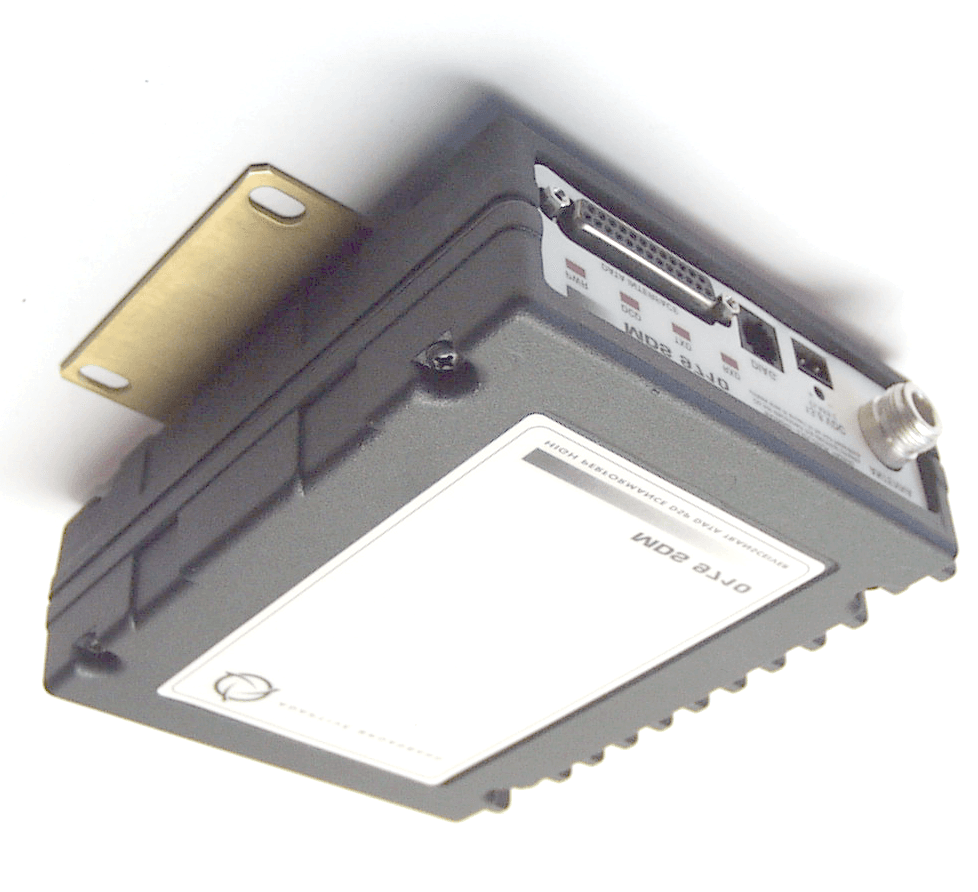
Click to zoom
Application Details
- Equipment Class
- TNB - Licensed Non-Broadcast Station Transmitter
- Date of Grant
- Nov 29, 2000
- Application Purpose
- Original Equipment
- Date of Application
- Sep 06, 2000
- Equipment Note
- 9710A Data Transceiver
- Frequency Range
- 806.00000000 - 940.00000000
- Company
- GE MDS, LLC
- Country
- United States
Documents & Files
Document Text
Text extracted from the exhibit documents filed with the FCC. Open a document above to read the original.
Users Manual
Installation and Operation Guide MDS 05-3305A01, REV. A JANUARY 1999 Data Transceiver MDS 4710A/9710A QUICK START GUIDE Below are the basic steps for installing the transceiver. Detailed instructions are given in “INSTALLA- TION” on page 9 of this guide. 1. Install and connect the antenna system to the radio • Use good quality, low loss coaxial cable. Keep the feedline as short as possible. • Preset directional antennas in the direction of desired transmission. 2. Connect the data equipment to the radio’s INTERFACE connector • Connection to the radio must be made with a DB-25 Male connector. Connections for typical sys- tems are shown below. • Connect only the required pins. Do not use a straight-through RS-232 cable with all pins wired. • Verify the data equipment is configured as DTE. (By default, the radio is configured as DCE.) 3. Apply DC power to the radio (10.5–16 Vdc @ 2.5 A minimum) • Observe proper polarity. The red wire is the positive lead; the black is negative. 4. Set the radio’s basic configuration with a Hand-Held Terminal (HHT) • Set the transmit frequency ( TX xxx.xxxx ). • Set the receive frequency ( RX xxx.xxxx ). • Set the baud rate/data interface parameters as follows. Use the BAUD xxxxx abc command, where xxxxx equals the data speed (110–38400 bps) and abc equals the communication parameters as follows: a = Data bits (7 or 8) b = Parity (N for None, O for Odd, E for Even c = Stop bits (1 or 2) (Example: BAUD 9600 8N1 ) NOTE: 7N1, 8E2 and 8O2 are invalid parameters and are not supported by the transceiver. 5. Verify proper operation by observing the LED display • Refer to Table 4 on page 14 for a description of the status LEDs. • Refine directional antenna headings for maximum receive signal strength using the RSSI command. DB-25DB-25 TRANSCEIVER (DCE) 2 3 2 3 RTU (DTE) 4 5 20 6DSR DSR 6 TXD RXD GND RTS CTS TXD RXD GND 4 CTS 5 RTS DB-9DB-25 DB-9 to DB-25 ExampleDB-25 to DB-25 Example 11 4 5 TRANSCEIVER (DCE) 2 3 3 2 RTU (DTE) 5 20 7 RXD TXD DCD GN D DSR RTS RXD TXD DCD GN D As required for application 5 18 7 6 CTS DSR RTS CTS8 6 4 5 77 GND GND 88 DCD DCD As required for application MDS 05-3305A01, Rev. AInstallation and Operation Guidei TABLE OF CONTENTS 1.0 GENERAL.................................................................................... 1 1.1 Introduction ...................................................................................... 1 1.2 Applications ...................................................................................... 2 1.3 Model Number Codes ...................................................................... 4 1.4 Accessories ...................................................................................... 5 2.0 GLOSSARY OF TERMS.............................................................. 6 3.0 INSTALLATION ............................................................................ 9 3.1 Installation Steps .............................................................................. 9 3.2 Transceiver Mounting ..................................................................... 11 3.3 Antennas and Feedlines ................................................................ 11 3.4 Power Connection .......................................................................... 13 3.5 Data Interface Connections ............................................................ 13 3.6 Using the Radio’s Sleep Mode ....................................................... 13 4.0 OPERATION .............................................................................. 15 4.1 LED Indicators ................................................................................ 16 4.2 RSSI Measurement ........................................................................ 16 5.0 TRANSCEIVER PROGRAMMING ............................................ 17 5.1 Hand-Held Terminal Connection & Startup .................................... 17 5.2 Hand-Held Terminal Setup ............................................................. 18 5.3 Keyboard Commands ..................................................................... 19 5.4 Detailed Command Descriptions ................................................... 22 6.0 TROUBLESHOOTING ............................................................... 31 6.1 LED Indicators ................................................................................ 32 6.2 Event Codes ................................................................................... 32 7.0 TECHNICAL REFERENCE ....................................................... 34 7.1 MDS 4710A/9710A Transceiver Specifications .............................. 34 7.2 Helical Filter Adjustment ................................................................ 36 7.3 Performing Network-Wide Remote Diagnostics ............................. 37 7.4 Upgrading the Radio’s Software ..................................................... 39 7.5 dBm-Watts-Volts Conversion Chart ................................................ 40 INDEX................................................................................................ I-1 IN CASE OF DIFFICULTY... ..................................... Inside Rear Cover iiMDS 4710/9710 Installation and Operation Guide MDS 05-3305A01, Rev. A.1 Copyright Notice This Installation and Operation Guide and all software described herein are protected by copyright: 1998 Microwave Data Systems , a division of California Microwave, Inc. All rights reserved. Microwave Data Systems reserves its right to correct any errors and omissions. Operational Safety Notices The radio equipment described in this guide uses radio frequency trans- mitters. Although the power level is low, the concentrated energy from a directional antenna may pose a health hazard. Do not allow people to come closer than 0.5 meter to the front of the antenna when the trans- mitter is operating. This manual is intended to guide a professional installer to install, operate…
Text truncated - open the document above for the full version.
Users Manual
MDS 05-3305A01, Rev. BMDS 4710/9710 I/O Guideiii Copyright Notice This Installation and Operation Guide and all software described herein are protected by copyright: 2000 Microwave Data Systems Inc . All rights reserved. Microwave Data Systems Inc. reserves its right to correct any errors and omissions in this publication. Antenna Installation Warning 1. All antenna installation and servicing is to be performed by qualified technical personnel only. When servicing the antenna, or working at distances closer than those listed below, ensure the transmitter has been disabled. Output is measured at the antenna terminal of the transmitter. The antenna(s) used for this transmitter must be fixed-mounted on outdoor permanent structures to provide the minimum separation distances described in this filing for satisfying RF exposure compliance requirements. When applicable, RF exposure compliance may need to be addressed at the time of licensing, as required by the responsible FCC Bureau(s), including antenna co-location requirements of ‘1.1307(b)(3). 2. Typically, the antenna connected to the transmitter is a directional (high gain) antenna, fixed-mounted on the side or top of a building, or on a tower. Depending upon the application and the gain of the antenna, the total composite power could exceed 200 watts EIRP. The antenna location should be such that only qualified technical personnel can access it, and that under normal operating conditions no other person can touch the antenna or approach within 3 meters of the antenna. RF Exposure Separation distances required for FCC RF Exposure compliance Antenna Gain vs. Recommended Safety Distance (MDS 4710 Series) Antenna Gain (MDS 4710 Series) 0–5 dBi5–10 dBi10–16.5 dBi Minimum RF Safety Distance 0.79 meter1.41 meters3.05 meters Antenna Gain vs. Recommended Safety Distance (MDS 9710 Series) Antenna Gain (MDS 9710 Series) 0–5 dBi5–10 dBi10–18.65 dBi Minimum RF Safety Distance 0.53 meter0.94 meter2.58 meters ivMDS 4710/9710 I/O GuideMDS 05-3305A01, Rev. B ISO 9001 Registration Microwave Data Systems' adheres to this internationally accepted quality system standard. MDS Quality Policy Statement We, the employees of Microwave Data Systems Inc., are committed to understanding and exceeding our customer’s needs and expectations. •We appreciate our customer’s patronage. They are our business. •We promise to serve them and anticipate their needs. •We are committed to providing solutions that are cost effective, innovative and reliable, with consistently high levels of quality. •We are committed to the continuous improvement of all of our systems and processes, to improve product quality and increase customer satisfaction. FM/UL/CSA Notice This product is available for use in Class I, Division 2, Groups A, B, C & D Hazardous Locations. Such locations are defined in Article 500 of the National Fire Protection Association (NFPA) publication NFPA 70, otherwise known as the National Electrical Code. The transceiver has been recognized for use in these hazardous locations by three independent agencies —Underwriters Laboratories (UL), Fac- tory Mutual Research Corporation (FMRC) and the Canadian Standards Association (CSA). The UL certification for the transceiver is as a Rec- ognized Component for use in these hazardous locations, in accordance with UL Standard 1604. The FMRC Approval is in accordance with FMRC Standard 3611. The CSA Certification is in accordance with CSA STD C22.2 No. 213-M1987. FM/UL/CSA Conditions of Approval: The transceiver is not acceptable as a stand-alone unit for use in the haz- ardous locations described above. It must either be mounted within another piece of equipment which is certified for hazardous locations, or installed within guidelines, or conditions of approval, as set forth by the approving agencies. These conditions of approval are as follows: 3. The transceiver must be mounted within a separate enclosure which is suitable for the intended application. 4. The antenna feedline, DC power cable and interface cable must be routed through conduit in accordance with the National Electrical Code. MDS 05-3305A01, Rev. BMDS 4710/9710 I/O Guidev 5. Installation, operation and maintenance of the transceiver should be in accordance with the transceiver's installation manual, and the National Electrical Code. 6. Tampering or replacement with non-factory components may adversely affect the safe use of the transceiver in hazardous loca- tions, and may void the approval. 7. When installed in a Class I, Div. 2, Groups A, B, C or D hazardous location, observe the following: WARNING —EXPLOSION HAZARD— Do not disconnect equipment unless power has been switched off or the area is known to be non-hazardous. Refer to Articles 500 through 502 of the National Electrical Code (NFPA 70) for further information on hazardous locations and approved Division 2 wiring methods. Revision Notice While every reasonable effort has been made to ensure the accuracy of this manual, product improvements may result in minor differences between the manual and the product shipped to you. If you have addi- tional questions or need an exact specification for a product, please con- tact our Customer Service Team using the information at the back of this guide. In addition, manual updates can often be found on the MDS Web site at www.microwavedata.com. Distress Beacon Warning In the U.S.A., the 406 to 406.1 MHz band is reserved for use by distress beacons. Since the MDS 4710A radio is capable of transmitting in this band, take precautions to prevent the radio from transmitting between 406 to 406.1 MHz. This notice applies only to MDS 4710A Transceivers used in the U.S.A. viMDS 4710/9710 I/O GuideMDS 05-3305A01, Rev. B
Block Diagram
Block Diagram of MDS 9710 Data Transceiver: Synthesizer 455KHz Discriminator Digital Signal Processor Microprocessor D/A Converter A/D Converter 16 MHz 81.745 MHz 82.2 MHz, 30KHz BW 455 KHz, 9KHz BW TCXO MOD PWR CONT VCO MOD Power Amp BASEBAND RSSI Receiver Front End 1ST IF 2ND IF Buffer Amp LO Amp Antenna Connector SYNTH CLK, LOAD, DATA Synthesizer REV PWR DET MDS 9710 BPFLNABPF LPF DIR CPLR vco vco LPF LPF TX: 928 - 960 MHz RX: 928 - 960 MHz INJ: 845.8 - 877.8 MHz DATA I/O
Cover Letter(s)
UltraTech Group of Labs August 28, 2000 FEDERAL COMMUNICATIONS COMMISSION 7435 Oakland Mills Road Columbia, MD 21046 USA Subject: Type Acceptance Application under FCC CFR 47, Parts 2 and 90 (Subpart I) - Radio Services Transmitters Operating in 806-821, 851-866, 896-901 and 935-940 MHz Frequency Bands [25 kHz (806-821 and 851-866 Frequency Bands) and 12.5 kHz (896-901 and 935-940 MHz Frequency Bands) Channel Spacing] Applicant: MICROWAVE DATA SYSTEMS INC. Product: RADIO TRANSCEIVER Model: 9710A FCC ID: E5MDS9710-1 Dear Sir/Madam, As appointed agent for MICROWAVE DATA SYSTEMS, INC., we would like to submit the application to the Federal Communications Commission for certification of the above product. Please review all necessary files uploaded to FCC OET site. If you have any queries, please do not hesitate to contact us by our TOLL FREE numbers: OUR TELEPHONE NO.: 1-877-765-4173 Yours truly, Tri Minh Luu, P. Eng., V.P., Engineering TML/AK Encl. 2 3000 Bristol Circle, Oakville, Ontario, Canada L6H 6G4 Telephone (905) 829-1570 Facsimile (905) 829-8050 Website: www.ultratech-labs.com Email: [email protected]
External Photos
EXHIBIT 10 EXTERNAL EUT PHOTOS PHOTO 1 OF 2 FCC ID: E5MDS9710-1 EXHIBIT 10 EXTERNAL EUT PHOTOS PHOTO 2 OF 2 FCC ID: E5MDS9710-1
ID Label/Location Info
17 6.0 Product Label The label which will be used on the MDS 9710A Data Transceiver is shown below. This label will be used after Type Acceptance has been granted by the FCC. CANADA: FCC ID: E5MDS9710-1 Location of identification label: (Also see Photograph 2) Identification Label with FCC ID: E5MDS9710-1
Internal Photos
EXHIBIT 12 INTERNAL EUT PHOTOS PHOTO 1 OF 6 FCC ID: E5MDS9710-1 EXHIBIT 12 INTERNAL EUT PHOTOS PHOTO 2 OF 6 FCC ID: E5MDS9710-1 EXHIBIT 12 INTERNAL EUT PHOTOS PHOTO 3 OF 6 FCC ID: E5MDS9710-1 EXHIBIT 12 INTERNAL EUT PHOTOS PHOTO 4 OF 6 FCC ID: E5MDS9710-1 EXHIBIT 12 INTERNAL EUT PHOTOS PHOTO 5 OF 6 FCC ID: E5MDS9710-1 EXHIBIT 12 INTERNAL EUT PHOTOS PHOTO 6 OF 6 FCC ID: E5MDS9710-1
Operational Description
1 Technical Report MICROWAVE DATA SYSTEMS MODEL 9710A DATA TRANSCEIVER FCC ID: E5MDS9710-1 Microwave Data Systems 175 Science Parkway Rochester, NY 14620 716 242 9600 (Voice) 716 241 5590 (Fax) 2 Table of Contents Section Description Pages List of Exhibits 3 1.0 General Equipment Information 4 1.1 Summary of RF Parameters 4 1.2 Construction Details 4 2.0 Description of Device Operation 5 2.1 General Operation 5 2.2 Description of Circuit Functions 5 2.2.1 Receiver 5 2.2.2 Power Supply 6 2.2.3 Transmitter 7 2.2.4 Processors 9 2.2.5 PLL/Synthesizers 10 2.2.6 RS-232 Data Interface 10 2.2.7 LED Indicators 10 3.0 Block Diagram 11 3.5 Schematic Diagram ( 3 sheets) 12,13,14 4.0 Design Considerations for EMC 15 5.0 Quality System at MDS 16 6.0 Product Labels 17 3 List of Exhibits Exhibit A: Technical Report (this document) Exhibit B: Test Report to FCC Parts 2, 15 and 90 Exhibit C: Installation and Operation Manual - MDS 9710A Exhibit D: Product Photographs (6) 1. MDS 9710 Transceiver - Front View 2. MDS 9710 Transceiver - Rear View 3. MDS 9710 Transceiver - Top View with top cover removed 4. MDS 9710 Transceiver - Top View of printed circuit board 5. MDS 9710 Transceiver - Top View of printed circuit board with internal shield removed 6. MDS 9710 Transceiver - Bottom View of printed circuit board 4 1.0 General Equipment Information This device is marketed and manufactured by Microwave Data Systems as the MDS 9710 Data Transceiver and is intended primarily for use in Point-to- Multipoint networks. The MDS 9710 is used as the remote radio in the multiple points in the network which communicate with a master station. 1.1 Summary of RF Parameters Transmitter Type: Synthesized, 12.5 kHz steps Frequency Range: 806 to 940 MHz. Power Output: 37 dBm maximum (5 Watts) Crystal frequency: 16 MHz TCXO Receiver Type: Double conversion superheterodyne Frequency Range: 806 to 940 MHz. 1st Local Oscillator Range: 723.8 to 857.8 MHz. First Intermediate Frequency: 82.2 MHz. Second Intermediate Frequency: 455 kHz. Crystal Frequencies: 16 MHz, 81.745 MHz. 1.2 Construction Details The MDS 9710 Data Transceiver consists of a transmitter and receiver constructed on a common printed wiring board assembly, sharing many common circuits. The transceiver board is mounted within a die-cast aluminum housing. A die-cast aluminum top cover completes the enclosure assembly, providing a well-shielded enclosure. Power, interface and antenna connections are made via connectors on the front face of the transceiver package. DC power may be supplied to the transceiver from any suitable DC source capable of supplying 13.8 VDC nominal at a maximum of 2.5 Amperes. The DC power source should be current limited or have a protective fuse or circuit breaker. 5 2.0 Description of Device Operation 2.1 General Operation The MDS 9710 Data Transceiver is a narrow band radio designed to operate on 12.5 kHz. channels, meeting the requirements of FCC Part 2, FCC part 15 and FCC Part 90. 2.2 Description of Circuit Functions The following is a summary of the operation of the MDS 9710 Transceiver. Refer to Figure 1, the block diagram, and to the schematics, to follow the discussion. 2.2.1 Receiver Receive Front End Connector J301 on the main PWB board conducts the RF signal from the front panel antenna connector to the antenna switch network. In the receive mode, one port of the antenna switch conducts the receive signal to the input of helical filter FL300. The output of FL300 is fed to RF amplifier Q302, whose output goes to helical filter FL302. Each helical front-end filter has a 25 MHz 1 dB bandwidth, and are down approximately 20 dB at ±100 MHz. The output of FL302 output goes to M301, a double-balanced mixer whose local oscillator injection voltage is derived from the VCO U307. High IF The 82.2 MHz High IF signal from M301 enters IF amplifier transistor Q301, whose output goes to FL308 and FL303, a dual SAW filter which provides part of the IF selectivity of the receiver. The output of FL303 is connected to U302, which contains the Low IF amplifier and other functions. Low IF U302 contains several circuit sections: mixer, oscillator, IF amplifier / limiter, quadrature detector and meter drive. The oscillator section of U302 uses crystal Y301and associated components to set the second oscillator frequency at 81.745 MHz. The 455 kHz output of the second mixer is fed to a ceramic filter set consisting of FL307 and FL309. This filter set provides the main adjacent channel selectivity of the receiver. 6 The output of FL309 is fed to the limiter amplifier input pin of U302. The limiter output is fed to a quadrature detector circuit tuned by FL301; audio recovered from the detector appears on Pin 8 of U302. A secondary output of the IF subsystem at Pin 5 of U302 gives a received signal strength indication (RSSI) voltage. Digital Signal processing Audio processing The unfiltered recovered audio from the IF detector passes through amplifier U201 to an A/D converter U205 and then processed by the DSP U202 to decode the digital information. RSSI Processing The unfiltered RSSI from the IF detector passes through a low pass filter to a monolithic internal A/D converter built within the 68HC11 micocontroller U101. A scaled version of the RSSI signal is output though the D/A converter U203 connected to the DSP U202. 2.2.2 Power Supply The + 14 volt (nominal) DC input appears when an external power source is connected to J103. From J1, the +14V is conducted to the internal transceiver circuits through F1, a 4 ampere board-mounted self-resetting poly fuse. CR112 is a transient voltage suppresser on the + 14 VDC primary power input. It protects against a reverse polarity condition. U105 is a switching regulator that provides + 5.6 volts for transceiver circuits. • U102 regulates the + 5.6 volts down to + 5 volts which supplies power to the microprocessor and all of the CMOS logic. • U204 regulates the + 5.6 volts down to + 3.3 volts which supplies power to the D…
Text truncated - open the document above for the full version.
RF Exposure Info
MDS 05-3305A01, Rev. BMDS 4710/9710 I/O Guidei TABLE OF CONTENTS 1.0 GENERAL ................................................................................... 1 1.1 Introduction ...................................................................................... 1 1.2 Applications ...................................................................................... 2 Point-to-Multipoint, Multiple Address Systems (MAS) ........................ 2 Point-to-Point System .........................................................................3 Continuously Keyed versus Switched Carrier Operation .................... 3 Single Frequency (Simplex) Operation ...............................................3 1.3 Model Number Codes ...................................................................... 3 1.4 Accessories ...................................................................................... 4 2.0 GLOSSARY OF TERMS.............................................................. 6 3.0 INSTALLATION ............................................................................ 9 3.1 Installation Steps .............................................................................. 9 3.2 Transceiver Mounting ..................................................................... 11 3.3 Antennas and Feedlines ................................................................ 11 Feedlines ..........................................................................................12 3.4 Power Connection .......................................................................... 13 3.5 Data Interface Connections ............................................................ 13 3.6 Using the Radio’s Sleep Mode ....................................................... 13 System Example............................................................................... 13 4.0 OPERATION .............................................................................. 15 4.1 LED Indicators ................................................................................ 16 4.2 RSSI Measurement ........................................................................ 16 5.0 TRANSCEIVER PROGRAMMING ............................................ 17 5.1 Hand-Held Terminal Connection & Startup .................................... 17 5.2 Hand-Held Terminal Setup ............................................................. 18 5.3 Keyboard Commands ..................................................................... 19 Entering Commands .........................................................................19 Error Messages ................................................................................ 19 5.4 Detailed Command Descriptions ................................................... 22 AMASK [0000 0000–FFFF FFFF] ....................................................22 ASENSE [HI/LO]............................................................................... 23 BAUD [xxxxx abc] ............................................................................. 23 BUFF [ON, OFF]............................................................................... 24 CKEY [ON–OFF] ..............................................................................24 CTS [0–255] .....................................................................................24 DATAKEY [ON, OFF] ........................................................................ 24 DEVICE [DCE, CTS KEY] ................................................................ 25 DKEY ................................................................................................ 25 DLINK [ON/OFF/xxxx] ...................................................................... 25 iiMDS 4710/9710 I/O GuideMDS 05-3305A01, Rev. B DMGAP [xx] ...................................................................................... 25 DTYPE [NODE/ROOT] ..................................................................... 26 DUMP ............................................................................................... 26 HREV................................................................................................ 26 INIT................................................................................................... 26 INIT [4710/9710] ............................................................................... 26 INIT [4720/9720] ............................................................................... 27 KEY .................................................................................................. 27 MODEL ............................................................................................. 27 MODEM [xxxx, NONE] ..................................................................... 27 OWM [XXX...] ................................................................................... 27 OWN [XXX...].................................................................................... 27 PTT [0–255] ...................................................................................... 27 PWR [20–37] .................................................................................... 27 RSSI .................................................................................................28 RTU [ON/OFF/0-80].......................................................................... 28 RX [xxx.xxxx] .................................................................................... 28 RXTOT [NONE, 1-255] ..................................................................... 28 SCD [0-255] ...................................................................................... 29 SER .................................................................................................. 29 SHOW [DC, PORT, PWR]................................................................. 29 SNR .......................................................................................…
Text truncated - open the document above for the full version.
RF Exposure Info
MDS 05-3305A01, Rev. BMDS 4710/9710 I/O Guidei TABLE OF CONTENTS 1.0 GENERAL.................................................................................... 1 1.1 Introduction ...................................................................................... 1 1.2 Applications ...................................................................................... 2 Point-to-Multipoint, Multiple Address Systems (MAS) ........................ 2 Point-to-Point System ......................................................................... 3 Continuously Keyed versus Switched Carrier Operation .................... 3 Single Frequency (Simplex) Operation ............................................... 3 1.3 Model Number Codes ...................................................................... 3 1.4 Accessories ...................................................................................... 4 2.0 GLOSSARY OF TERMS.............................................................. 6 3.0 INSTALLATION ............................................................................ 9 3.1 Installation Steps .............................................................................. 9 3.2 Transceiver Mounting ..................................................................... 11 3.3 Antennas and Feedlines ................................................................ 11 Feedlines .......................................................................................... 12 3.4 Power Connection .......................................................................... 13 3.5 Data Interface Connections ............................................................ 13 3.6 Using the Radio’s Sleep Mode ....................................................... 13 System Example............................................................................... 13 4.0 OPERATION .............................................................................. 15 4.1 LED Indicators ................................................................................ 16 4.2 RSSI Measurement ........................................................................ 16 5.0 TRANSCEIVER PROGRAMMING ............................................ 17 5.1 Hand-Held Terminal Connection & Startup .................................... 17 5.2 Hand-Held Terminal Setup ............................................................. 18 5.3 Keyboard Commands ..................................................................... 19 Entering Commands......................................................................... 19 Error Messages ................................................................................ 19 5.4 Detailed Command Descriptions ................................................... 22 AMASK [0000 0000–FFFF FFFF] .................................................... 22 ASENSE [HI/LO]............................................................................... 23 BAUD [xxxxx abc] ............................................................................. 23 BUFF [ON, OFF]............................................................................... 24 CKEY [ON–OFF] .............................................................................. 24 CTS [0–255] ..................................................................................... 24 DATAKEY [ON, OFF] ........................................................................ 24 DEVICE [DCE, CTS KEY] ................................................................ 25 DKEY ................................................................................................ 25 DLINK [ON/OFF/xxxx] ...................................................................... 25 iiMDS 4710/9710 I/O GuideMDS 05-3305A01, Rev. B DMGAP [xx] ........…
Text truncated - open the document above for the full version.
Contact Information
Applicant
John Barenys(Senior Operations Manager)
Technical Contact
Ultratech Engineering Labs Inc.Tri M Luu
[email protected]1-877-765-4173
3000 Bristol Circle · Oakville, Ontario · Canada
Non-Technical Contact
Ultratech Engineering Labs Inc.Tri M Luu
[email protected]1-877-765-4173
Test Firm
UltraTech Engineering Labs Inc.Tri Luu
Technical Specifications
| # | Rule Parts | Frequency Range | Power Output | Emission | Tolerance |
|---|---|---|---|---|---|
| 1 | 90 | 806 MHz - 940 MHz | 6 W | 11K2F1D | 1.3000000000 ppm |
Other Applications from GE MDS, LLC

E5MDS-NET9S
Jul 13, 2023Frequency Hopping Radio
Equipment Class
DSS - Part 15 Spread Spectrum Transmitter
E5MDS-NET9L
Jul 11, 2023Frequency Hopping Radio
Equipment Class
DSS - Part 15 Spread Spectrum Transmitter
E5MDS-LN900
Jan 27, 2016Industrial Radio Module
Equipment Class
TNB - Licensed Non-Broadcast Station Transmitter
E5MDS-SDM4
Aug 20, 2015MDS SDM4 Licensed Spectrum Module
Equipment Class
TNB - Licensed Non-Broadcast Station Transmitter
E5MDS-LN400
Jul 09, 2015Industrial Radio Module
Equipment Class
TNB - Licensed Non-Broadcast Station Transmitter