E8HMSR0305TWireless Mouse
Chicony Electronics Co Ltd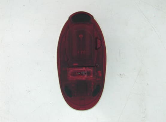
Click to zoom
Application Details
- Equipment Class
- DXX - Part 15 Low Power Communication Device Transmitter
- Date of Grant
- Sep 17, 2003
- Application Purpose
- Original Equipment
- Date of Application
- Sep 17, 2003
- Equipment Note
- Wireless Mouse
- Frequency Range
- 27.04500000 - 27.04500000
- Company
- Chicony Electronics Co Ltd
- Country
- Taiwan
Documents & Files
Document Text
Text extracted from the exhibit documents filed with the FCC. Open a document above to read the original.
Users Manual
A. FEDERAL COMMUNICATIONS COMMISSION (FCC) STATEMENT This equipment has been tested and found to comply with the limits for a Class B digital device, Pursuant to Part 15 the FCC rules. These limits are designed to provide reasonable protection against harmful interference in a residential installation. This equipment generates, uses and can radiate radio frequency energy and, if not installed and used in accordance with the instructions, may cause harmful interference to radio communications. However, there is no guarantee that interference will not occur in a particular installation. If this equipment does cause harmful interference will not occur in a particular installation. If this equipment does cause harmful interference to radio or television reception, which can be determined by turning the equipment off and on, the user is encouraged to try to correct the interference by one or more of the following measures: • Reorient or relocate the receiving antenna. • Increase the separation between the equipment and receiver. • Connect the equipment into an outlet on a circuit different from that to which the receiver is connected. • Consult the dealer or an experienced radio/TV technician for help. This device complies with part 15 of the FCC rules. Operation is subject to the following two conditions: (1) This device may not cause harmful interference, and (2) This device must accept any interference received, including interference that may cause undesired operation. WARNING: Use only shielded cables to connect I/O devices to this equipment. You are cautioned that changes or modifications not expressly approved by the party responsible for compliance could void your authority to operate the equipment. CAUTION: AVOID PROLONGED USE OF THE KEYBOARD WITHOUT BREAKS. Take regular breaks and keep a good posture. Consult your physician promptly if you notice any lost of motion or pain in your wrist when using the keyboard. INFORMATION FOR OPTICAL POINTING DEVICES ONLY : User-observable light is 15 microwatts in normal operation. This product has been tested to comply with international Standard IEC 60825-1:(1993), incid. Amd.2(2001). This product uses LEDs that are inherently Class 1. Class 1 LED Product B. PRODUCT SPECIFICATION 1. SYSTEM AND INTERFACE Receiver Interface: USB interface designed to be fully compatible with Microsoft Windows 98, ME, 2000, XP system. 2. HOT KEYS Implements 17 hot keys to easy access as below function: Volume down, Mute, Volume up, Previous track, Stop, Play, Next track, Wake up, Sleep, Shut down, Internet, Email, Search, My favorite, Calculator, Backward, and Forward function. 3. FREQUENCY BAND : Keyboard – 27.195 MHz Mouse – 27.045 MHz 4. FREQUENCY MODULATION : FSK MODE 5. POWER RATING : Keyboard: 3 V , 30 mA (MAX)_ Mouse: 3 V , 50 mA (MAX)_ Receiver: 5 V , 100mA (MAX) for USB 6. BATTERY: Keyboard: 2 pieces of AA Batteries Mouse: 2 pieces of AA Batteries 7. BATTERY LIFE TIME : Keyboard: 500 hours reference (operating mode) Mouse: 60 hours reference (operating mode) 8. OPERATION DISTANCE Keyboard: 6 feet without signal disturbance and no direction limit. Mouse: 5 feet without signal disturbance and no direction limit. 9. MOUSE DETECTION METHOD Mouse: Mechanical tracking method (Roll ball optical sensor) 10. MOUSE RESOLUTION: 400 DPI 11. OPERATING TEMPERATURE : 0º C~ 40º C. 12 STORAGE TEMPERATURE : -10º C ~ 60º C. C. HARDWARE INSTALLATION 1. Plug the receiver connector into an USB port. 2. SYSTEM will take around 10 sec to find your keyboard and mouse automatically. (PS : If your OS is Windows® 98, please follow the screen instruction to complete your keyboard and mouse installation) 3. Please keep your receiver from the other electrical devices about 8 inches. The other electrical devices may influence your receiver sensitivity. 4. Put two batteries into your keyboard battery chamber, and another two batteries into your mouse battery chamber. D. BATTERY STATUS 1. There is one LED on the top of receiver. The LED will be blinking during the ID setting or data received. The LED will be always ON, if the battery status of keyboard or mouse is low. Please prepare one set of batteries in case of keyboard or mouse working abnormal. E. ID CHANGE Note: This is a single channel product. There is one individual channel for the keyboard and another one channel for the mouse. Different ID still can keep your mouse or keyboard working fine at the same channel, but please keep two sets of keyboard and mouse are not close to 6 feet between each others. Please press the button on the receiver. The LED will be twinkling slowly. Remove the battery and press any key several times. Put the batteries back to the battery chamber, and then you will see the LED of receiver will be twinkling fast momentarily. The device is working now. The Keyboard and Mouse use the same way to change the ID. Note: This is very important !! After you remove the battery, please press any key several times to release all electrical current inside the device, otherwise the device may be not workable after battery put in." F. HOTKEYS FUNCTION A brief introduction is for the hotkey functionality. 1. Decreasing the volume This key decreases the volume of the connected loudspeakers. 2. Mute Use this key to switch on/off the connected loudspeaker. 3. Increasing the volume This key increases the volume of the connected loudspeakers. 4. Previous Track Use this key to skip to the forward title in the active player. 5. Stop Use this key to end the playback of a title. 6. Play/Pause Use this key to start or pause for a short time the playback of a title just as you use a normal CD player. 7. Next Track Use this key to skip to the next title in the active player. 8. Wake up Wake up system from sleep status. 9. Sleep Switch computer status to “Standby mode”. Note: The “Standby mode” key only functions correctly when the system board, BIOS and operating system of your system fully support the ACPI function. 10. Shut down …
Text truncated - open the document above for the full version.
External Photos
NEUTRON EMC LAB. Report No.NEI-FCC-P-03027 24/34 Photo # 1
ID Label/Location Info
NEUTRON EMC LAB. Report No.NEI-FCC-P-03027 31/34 -- FCC ID label -- The remained portion of label statement required by FCC is attached in the user’s manual. n Location of Label on EUT -- 0.3 cm 2.2 cm
Internal Photos
NEUTRON EMC LAB. Report No.NEI-FCC-P-03027 25/34 Photo # 2 NEUTRON EMC LAB. Report No.NEI-FCC-P-03027 26/34 Photo # 3 NEUTRON EMC LAB. Report No.NEI-FCC-P-03027 27/34 Photo # 4 NEUTRON EMC LAB. Report No.NEI-FCC-P-03027 28/34 Photo # 5
Test Report
NEUTRON EMC LAB. Report No.NEI-FCC-P-03027 2/34 Declaration Neutron represents to the client that testing is done in accordance with standard procedures as applicable and that test instruments used has been calibrated with the standards traceable to National Measurement Laboratory (NML) of R.O.C., or National Institute of Standards and Technology (NIST) of U.S.A. Neutron's reports apply only to the specific samples tested under conditions. It is manufacture’s responsibility to ensure that additional production units of this model are manufactured with the identical electrical and mechanical components. Neutron shall have no liability for any declarations , inferences or generalizations drawn by the client or others from Neutron issued reports. Neutron’s reports must not be used by the client to claim product endorsement by the authorities or any agency of the Government. This report is the confidential property of the client. As a mutual protection to the clients, the public and Neutron-self, extracts from the test report shall not be reproduced except in full with Neutron’s authorized written approval. Neutron’s laboratory quality assurance procedures are in compliance with the ISO Guide 17025 requirements, and accredited by the conformity assessment authorities listed in this test report. Limitation For the use of the authority's logo is limited unless the Test Standard(s)/Scope(s)/Item(s) mentioned in this test report is (are) included in the conformity assessment authorities acceptance respective. Assessment Authorities Test Standard/Scope/Item Acceptance FCC Part 15 Subpart B IEC/CISPR22 AS/NZS 3548 CNS 13438 FCC Part 15 Subpart B CISPR 22/EN 55022 AS/NZS 3548 VCCI -Technical Requirement CNS 13438 SS IEC/CISPR 22 IEC/EN 61000-3-2 IEC/EN 61000-4-5 IEC/EN 61000-3-3 IEC/EN 61000-4-6 IEC/EN 61000-4-2 IEC/EN 61000-4-8 IEC/EN 61000-4-3 IEC/EN 61000-4-11 IEC/EN 61000-4-4 NEUTRON EMC LAB. Report No.NEI-FCC-P-03027 3/34 Table of Contents Page 1 General Information 5 1.1 Applicant 5 1.2 Manufacturer 5 1.3 Equipment Under Tested 5 1.4 OEM Brand/Model 5 1.5 Product Description 5 1.6 Connecting I/O Port(s) 5 1.7 Power Supplied 5 1.8 Products Covered 6 1.9 Model Difference (Series, Versions, if any) 6 1.10 EUT Modifications 6 1.11 Electric Block Diagram 6 1.12 Photos of EUT 6 2 RFI Emissions Measurement 7 2.1 Test Facility 7 2.2 Standard Compliance 7 2.3 Test Conditions and Channel 7 2.4 Test Methodology 7 2.5 Deviations from Standard Test Method 7 2.6 Sample(s) Tested 8 2.7 Measurement Instrument 8 2.8 Measurement Uncertainty 8 2.9 Tested System Set-Up/Configuration Details 8 Table -1 Equipments Used in Tested System 9 Diagram -1 Block diagram showing the configuration of system tested 10 Table - 2 Equipments Used in Tested System 11 Table - 3 Information of Interface Cable 11 2.10 Max.(Worst Case) RF Emission Evaluation 12 2.11 EUT Operation 12 3 Justification 13 3.1 Limitations 13 3.1.1 Power Line Conducted Emission 13 3.1.2 Radiated Emission Limits 13 3.2 Measurement Justification 14 3.2.1 Conducted Emission 14 3.2.2 Radiated Emission 14 3.2.3 Field Strength Calculation 15 3.3 Measurement Data 15 Table 4 Conducted Emission Data 15 Table 5 Radiated Emission Data 15 NEUTRON EMC LAB. Report No.NEI-FCC-P-03027 4/34 Table of Contents Page Attachment 18 A. Electric Block Diagram 19 B. EUT Modification Description 20 C. EUT Test Photos 21 D. EUT Photos 23 E. User’s Manual 29 F. Product Labeling 30 G. Bandwidth Requirement 32 H. Laboratory Accreditation Certificate 34 NEUTRON EMC LAB. Report No.NEI-FCC-P-03027 5/34 1. General Information 1.1 Applicant Name Chicony Electronics Co., Ltd. Address No. 25 Wu-Gong 6 Th Rd., Wu-Ku Industrial Park, Taipei Hsien, Taiwan, R.O.C. 1.2 Manufacturer Name N/A Address N/A 1.3 Equipment Under Tested Name: Wireless Mouse Trade Name: Chicony Model No.: MSR0305T 1.4 OEM Brand/Model (if applicable) OEM Brand(s)/Model(s) except the basic model in sub-clause 1.3 is(are) the follows: OEM Brand: N/A Model No.: N/A 1.5 Product Descriptions(Application/Features/Specification) The EUT is a Wireless Mouse. A major technical descriptions of EUT is described as following: A. Operation Frequency 27.045 MHz B. Modulation Type FSK C. Antenna Designation Integral D. Number Of Channel 1 E. Channel Spacing N/A F. Operation Methodology The EUT encoder generates a pulse code serially transmit (typical designation) into the modulator(or called as mixer) stage in circuit. This pulse signal mixed with the carrier at modulator(mixer) stage by way of FSK mode frequency modulation. The modulation depth is designed such as ± 5KHz in this application, that means the pulse(may be at high level state or low level state) will trigger the oscillator to generate a frequency at a specified fundamental frequency +5KHz or −5KHz, depended on the designation. For example, if the carrier frequency defined as fundamental frequency +5KHz at high level state, then the alternative carrier frequency will be fundamental frequency −5KHz at low level state. Based on the application, features, or specification exhibited in User's Manual, the EUT is considered as an ITE/Computing Device. More details of EUT technical specification, please refer to the User's Manual (Attachment - E.) NEUTRON EMC LAB. Report No.NEI-FCC-P-03027 6/34 1.6 Connecting I/O Port(s) Please refer to the User's Manual ( Attachment - E.) 1.7 Power Supplied Power Source: Battery supplied Power Cord: N/A Power Rating: DC 3 V, 50mA(Max) 1.8 Products Covered (if applicable) The sample tested including the following sub-system/module/accessory : Sub-system/ Module/ Accessory Model/Type No. Int. Inst./ Ext. Cont. Wireless Keyboard KBR0305 Ext. Receiver Wireless Desktop Receiver 1.0B Ext. 1.9 Model Difference (Series, Versions, if any) Except the basic model no. (model designation of the sample tested in this test report), additional model no. covered is(are) : N/A. 1.10 EUT Modifications (if applicable) No any modification required for the EUT to compl…
Text truncated - open the document above for the full version.
Test Report
NEUTRON EMC LAB. Report No.NEI-FCC-P-03027 33/34 Bandwidth Requirement
Test Setup Photos
NEUTRON EMC LAB. Report No.NEI-FCC-P-03027 22/34 Radiated Measurement Photos
Contact Information
Applicant
T. S. Chen(Manager)
Test Firm
BTL Inc.Andy Chiu
Technical Specifications
| # | Rule Parts | Frequency Range | Power Output |
|---|---|---|---|
| 1 | 15C | 27.045 MHz - 27.045 MHz | - |
Other Applications from Chicony Electronics Co Ltd
E8HWBS23B5LUB
Sep 19, 2023USI Rechargeable Active Pen
Equipment Class
DXX - Part 15 Low Power Communication Device Transmitter
E8HRG-2308
Sep 19, 2023Dongle
Equipment Class
DXX - Part 15 Low Power Communication Device Transmitter
E8HMG-2308
Sep 19, 2023Gaming Mouse
Equipment Class
DXX - Part 15 Low Power Communication Device Transmitter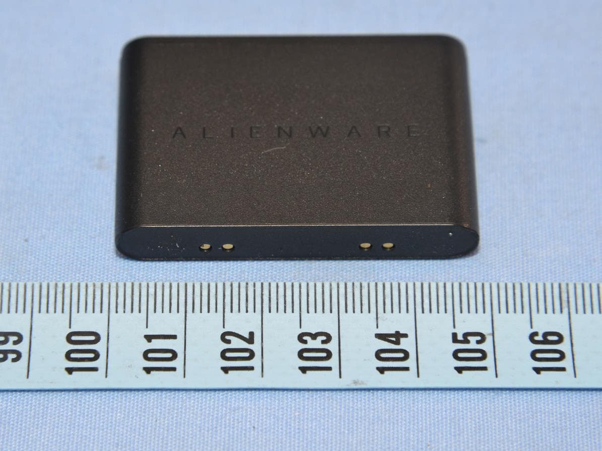
E8HKC-2227
Feb 01, 2023Gaming Keyboard
Equipment Class
DTS - Digital Transmission System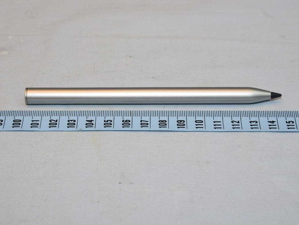
E8HTPA-C002P
Aug 09, 2021HP Wireless Rechargeable USI Pen
Equipment Class
DXX - Part 15 Low Power Communication Device Transmitter