EF4-00115Wireless glass break detector
Nice North America LLC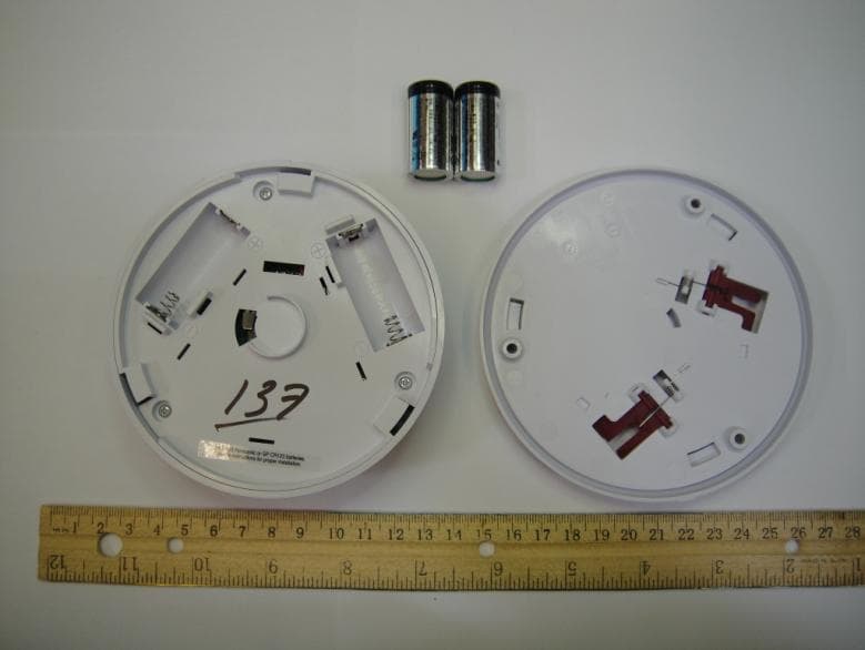
Click to zoom
Application Details
- Equipment Class
- DTS - Digital Transmission System
- Date of Grant
- Dec 14, 2013
- Application Purpose
- Original Equipment
- Date of Application
- Dec 14, 2013
- Equipment Note
- Wireless glass break detector
- Frequency Range
- 908.42000000 - 908.42000000
- Company
- Nice North America LLC
- Country
- United States
Documents & Files
Document Text
Text extracted from the exhibit documents filed with the FCC. Open a document above to read the original.
Users Manual
Copyright © 2013 Linear Corporation 235512 X8 GB00Z-1WIRELESSGLASS BREAKDETECTORInstallation Instructions 1. PRODUCT DESCRIPTIONThe Model GB00Z-1 is a battery powered glass break detector with built-in Z-Wave ® interoperable two-way RF mesh networking technology designed for use with Lowe’s Iris ® Smart Home Hub. This device is used for perimeter protection. The GB00Z-1 can send fi ve different signal types: fault, restore, low battery, status, and tamper. The Iris system hub must be paired with the glass break detector before system testing and operation. Refer to the Lowe’s Iris system Web site for details on pairing and testing the detector.In a typical installation, the detector is mounted on a wall or ceiling within 15 feet of the protected glass window(s). The unit uses dual-stage digital audio processing to detect the sound of breaking glass in a 360° area around the device. If the unit detects breaking glass, a fault signal is sent to the system followed by a restore signal. Periodically, the unit sends a status signal to update the system. If the battery tests low, a low battery signal is included with any transmission. The glass break detector is powered from two 3-Volt CR123A lithium batteries (included).An internal switch senses if the detector is removed from its base. Removing the detector will send a tamper signal to the system. Three screws and screw anchors are provided for mounting the detector. 2. FEATURES 3. INSTALLING OR CHANGING BATTERIES 4. PAIRING OR UN-PAIRING THE DETECTOR WITH THE HUB 5. MOUNTING THE DETECTOR 6. DETECTOR TESTING 7. SPECIFICATIONS Operating Temperature: 32° to 120° F (0° to 49° C) Operating Relative Humidity: 5 to 95%, non-condensing Operating Frequency: 908.42 MHz Battery Type: Two 3-Volt CR123A Lithium Batteries Sensor Type: Single microphone, dual-stage (thud & crash) The minimum size for all glass types is 11” x 11” (28 cm x 28 cm) square. Glass must be framed, in a wall of the room or mounted in a barrier of 36” (91 cm) minimum width. GLASS TYPE MINIMUM TO MAXIMUM THICKNESS PLATE 1/8” TO 1/4” (3.2 mm TO 6.4 mm) TEMPERED 1/8” TO 1/4” (3.2 mm TO 6.4 mm) SEALED, INSULATING 1/8” TO 1/4” (3.2 mm TO 6.4 mm) Z-Wave is a registered trademark of Sigma Designs Inc. and/or its subsidiaries. 8. LINEAR LIMITED RETAIL WARRANTYLinear LLC (the Company) warrants to the original purchaser that products delivered hereunder will be free of defects in materi als and workmanship for a period of one (1) year from the date of purchase.The Company within said period shall at its option, either repair or replace free of charge, any product or part thereof found, upon the Company’s inspection, to be so defective, and will return the repaired or replaced product to the purchaser at Company’s expens e. All products returned for warranty service require a Return Product Authorization Number (RPA#). For warranty service, shipping instructions, and an RPA#, contact Linear Technical Services at 1-800-421-1587. Devices must be sent to the Company at owner’s expense and be accompanied with statement of defect and proof of purchase.This warranty is conditioned on the following: 1. The Company must be notified within one year of purchase and have been given the opportunity of inspection by return of any alleged defective product free and clear of all liens and encumbrances to the Company or its distributor; and 2. The product must not have been abused, misused or improperly maintained and/or repaired during such period; and3. Such defect has not been caused by corrosion or exposure to other than ordinary wear and tear. THE COMPANY MAKES NO OTHER WARRANTY OR REPRESENTATION OF ANY KIND WHATSOEVER INCLUDING ANY WARRANTY OF MERCHANTABILITY OR FITNESS FOR A PARTICULAR PURPOSE ARE HEREBY DISCLAIMED.The Company’s maximum liability hereunder is limited to the purchased price of the product. In no event shall the Company be li able for any consequential, indirect, incidental or special damages of any nature arising from the sale or use of the product, whether based in contract, tort, strict liability or otherwise.Note: Some states do not allow limitations on incidental or consequential damages or how long an implied warranty lasts, so tha t the above limitations may not fully apply. This warranty gives specific legal rights and you may also have other rights which may vary fr om state to state. This device complies with FCC Part 15 and Canada Rules and Regulations. Operation is subject to the following two conditions: ( 1) This device may not cause harmful interference and (2) this device must accept any interference received, including interference that may cause undesired operation. Le présent appareil est conforme aux CNR d’Industrie Canada applicables aux appareils radio exempts de licence. L’exploitation est autorisée aux deux conditions suivantes : (1) l’appareil ne doit pas produire de brouillage, et (2) l’utilisateur de l’appareil doit acce pter tout brouillage radioélectrique subi, même si le brouillage est susceptible d’en compromettre le fonctionnement. PRINTER’S INSTRUCTIONS: INSTR,INSTL,GLASS BREAK,ZW - P/N: 235512 X8 - INK: BLACK - MATERIAL: 20 LB. MEAD BOND - SIZE: 11.000” X 8.500” - FOLDING: 4-FOL D ALTERNATE, FINISH WITH LOGO SHOWING - SCALE: 1-1 GLA SS BREAK DETECTOR RED 2ND S TAGE INDICATOR GREEN 1 S T S TAGE INDICATOR DETECTION MICROPHONE REMOVABLE MOUNTING BA S E MOUNTING S CREW S AND ANCHOR S TE S T BUTTON BA S E ALIGNMENT INDICATOR S IN S ERT TWO CR12 3 A BATTERIE S INTO BATTERY HOLDER S WARNING DANGER OF EXPLOSION IF BATTERIES ARE INSTALLED INCORRECTLY. REPLACE ONLY WITH THE SAME OR EQUIVALENT TYPE RECOMMENDED BY THE MANUFACTURER. OB S ERVE POLARITY !!! GREEN INDICATOR WILL FLA S H ONCE WHEN BATTERIE S ARE IN S TALLED LOCATE THE DETECTOR ON THEADJACENT OR OPPO S ITE WALL OR ON THE CEILING WITHIN 15 FEET OF THE WINDOW BEINGPROTECTED 1 2 U S E THE MOUNTING BA S E A S A TEMPLATE TO MARK THE LOCATIONOF THE THREE MOUNTING HOLE S 3 DRILL 3 /16" PILOT HOLE S FOR THE S C…
Text truncated - open the document above for the full version.
Users Manual
DETECTOR TESTING1. Follow the system’s instructions to select Test Mode. When instructed, press button on Detector (A) three times . SPECIFICATIONSOperating Temperature: 32° to 120° F (0° to 49° C) Operating Relative Humidity: 5 to 95%, non-condensing Operating Frequency: 908.42 MHz Sensor Type: Single microphone, dual-stage Glass Thickness: 1/8” (3.2 mm) to 1/4” (6.4 mm) HELPFUL TIPS• The minimum size for all glass types is 11” x 11” (28 cm x 28 cm) square. Glass must be framed, in a wall of the room or mounted in a barrier of 36” (91 cm) minimum width. • The Detector will not lock onto the Mounting Plate unless both CR123A batteries are installed. • The Detector sends Z-Wave ® signals to the system. Z-Wave ® is a registered trademark of Sigma Designs Inc. and/or its subsidiaries. WARRANTY Lowe’s Utilitech Warranty Here?? REGULATORY NOTICEChanges or modi fi cations to the device may void FCC compliance. Les modi fi cations apportées à l’appareil peuvent annuler la conformité Industrie Canada PARING INSTRUCTIONS1. Install two Batteries (CC) into the Detector (A). Observe polarity! 2. Bring detector within 10 feet of the system. Set system to add glass break detector device, when instructed, press the button on Detector (A) three times to pair with the system. MOUNTING THE DETECTOR1. Choose a location on the ceiling or on an adjacent or opposite wall within 12 feet of the glass to be monitored. Use the Mounting Plate (B) as a template to mark the three mounting holes. 2. Drill three 3/16” pilot holes and insert Screw Anchors (BB). Attach Mounting Plate (B) with three Mounting Screws (AA). 3. Match alignment marks on Detector (A) and Mounting Plate (B). Turn Detector (A) clockwise to lock onto Mounting Plate (B). ITEM #0000000 MODEL #GB00Z-1 GLASS BREAK DETECTOR Questions?Call customer service at 1-000-000-0000,5:00 a.m. - 4:30 p.m., PST, Monday-Friday PACKAGE CONTENTSHARDWARE CONTENTSNote: Hardware shown actual size. SAFETY INFORMATION Please read and understand this entire manual before attempting to assemble, operate, or install the product. WARNING Danger of explosion if batteries are installed incorrectly. Replace only with the same or equivalent type recommended by the manufacturer.PREPARATIONBefore beginning installation of product, make sure all parts are present. Compare parts with package contents list and hardware contents list. If any part is missing or damaged, do not attempt to assemble, install or operate the product.Estimated Installation Time: 15 minutes. Tools required for installation (not included):Pencil, Phillips screwdriver, drill, 3/16” drill bit x 1 Mounting Plate x 3 Mounting Screw x 3 Screw Anchor x 2 CR123A Battery x 1 Detector A AA CC CC A A B B A A B AA BB CC BB B xxxxx Printed in China PRINTER’S INSTRUCTIONS: INSTR,INSTL,GLASS BREAK,ZW - P/N: 235512 X11 - INK: BLACK - MATERIAL: 20 LB. MEAD BOND - SIZE: 11.000” X 8.500” - FOLDING: Z-FO LD, FINISH WITH LOGO SHOWING - SCALE: 1-1 235512 X11 1 3X 1 2 2 1 3 123 Utilitech & UT Design ® is a registered trademark of LF, LLC. All rights reserved.
Cover Letter(s)
LINEAR LLC 1950 CAMINO VIDA ROBLE, SUITE 150, CARLSBAD, CA 92008-6517 PHONE (760) 438-7000 ● (800) 421-1587 ● ENG. FAX (760) 438-7043 MAIL: P.O. BOX 9003 ● CARLSBAD, CA 92018-9003 December 6, 2013 TUV SUD BABT Octagon House, Concorde Way Sagensdworth Road North, Fareham PO15 5RL ATTN: Director of Certification AUTHORITY TO ACT AS AGENT On our behalf, I appoint TUV Sud, 10040 Mesa Rim Road, San Diego, CA 92121 to act as our agent in the preparation of certain FCC and IC applications for equipment certification. I certify that submitted documents properly describe the device or system for which equipment certification is sought. I also certify that each unit manufactured, imported or marketed, as described in Industry Canada regulations will have affixed to it a label identical to that submitted for approval with this application. For instances where our authorized agent signs the Linear LLC approved applications for certification, I acknowledge that all responsibility for complying with the terms and conditions for certification, as specified by TUV SUD BABT still resides with Linear LLC, Carlsbad, CA. This appointment is in effect until December 31, 2015 or otherwise terminated. Sincerely yours, Company Regulatory Compliance Engineer: John W. Kuivinen, P.E. Telephone Number: 760-438-7000 X7138 Email: [email protected]
Cover Letter(s)
LINEAR LLC 1950 CAMINO VIDA ROBLE, SUITE 150, CARLSBAD, CA 92008-6517 PHONE (760) 438-7000 ● (800) 421-1587 ● ENG. FAX (760) 438-7043 MAIL: P.O. BOX 9003 ● CARLSBAD, CA 92018-9003 Date 25 November 2013 TUV SUD BABT TCB Octagon House, Segensworth Road, Fareham, Hampshire, PO15 5RL Confidentiality Request FCC ID: EF4-00115 Pursuant to Sections 0.457(d)(1)(ii) and 0.459 of the Commission’s Rules, Linear LLC hereby requests permanent confidential treatment of information accompanying this application as outlined below: Schematics Bill of Materials/Parts List Linear LLC also hereby requests short-term confidential treatment of information accompanying this application as outlined below for a period of (up to 180) days: The above materials contain trade secrets and proprietary information not customarily released to the public. The public disclosure of these matters might be harmful to the Applicant and provide unjustified benefits to its competitors. The Applicant understands that pursuant to Rule 0.457(d)(1)(ii), disclosure of this Application and all accompanying materials will not be made before the date of the Grant for this Application. Yours sincerely, Reguatory Complaince Engineer: John W. Kuivinen, P.E. Telephone Number: 760-438-7000 X7138 Email: [email protected]
External Photos
FCC ID: EF4-00115 IC: 1078A-00115 Report No.: SC1310877 Page 1 of 2 FCC ID: EF4-00115 IC: 1078A-00115 Report No.: SC1310877 Page 2 of 2
ID Label/Location Info
FCC ID: EF4-00115 IC: 1078A-00115 Report No.: SC1310877 Page 1 of 2 FCC ID: EF4-00115 IC: 1078A-00115 Report No.: SC1310877 Page 2 of 2 Example Label location
Internal Photos
FCC ID: EF4-00115 IC: 1078A-00115 Report No.: SC1310877 Page 1 of 2 FCC ID: EF4-00115 IC: 1078A-00115 Report No.: SC1310877 Page 2 of 2
RF Exposure Info
December 06, 2013 TUV SUD BABT Octagon House, Concorde Way Segensworth Rd N, Fareham PO15 5RL Attention: Director of Certification RE: Analysis of RF Exposure/SAR Exemption for FCC and Industry Canada compliance purposes FCC ID: EF4-00115 IC: 1078A-00115 FCC Portable Exposure SAR Exemption Per FCC KDB 447498 D01 RF Exposure v05r01 Maximum power = 414.1uW e.i.r.p. f(GHz) = 0.9084 min. test separation distance = 5mm [(max. power of channel, including tune-up tolerance, mW)/(min. test separation distance, mm)] ·[√f(GHz)] ≤ 3.0 f(GHz) is the RF channel transmit frequency in GHz Power and distance are rounded to the nearest mW and mm before calculation17 The result is rounded to one decimal place for comparison [Ref: Clause 4.3.1.1] [(0.0004141mW)/(5, mm)] ·[√0.9084(GHz)] ≤ 3.0 0.00008 ≤ 3.0 Therefore, the device meets the FCC SAR exemption requirements. RF Exposure Categorical Exclusion Per 47CFR Rule Part 2.1091 Maximum power = 414.1uW e.i.r.p. f(GHz) = 0.9084 This device operates below 1.5GHz and has an effective radiated power of 0.00025mW (less than 1.5W) and is therefore categorically excluded from routine environmental evaluation for RF exposure prior to equipment authorization or use. MPE Compliance Information using the Power Density formula: where: S = power density P = power input to the antenna G = power gain of the antenna in the direction of interest relative to isotropic R = distance to the center of radiation of the antenna Measured radiated level @ 3 meters: 91.4 (dBμV/m) Measured radiated level converted to V/m: 0.037 (V/m) Maximum peak output power –Radiated: 0.0004141 (Watt) Antenna gain (typical): -3.85 (dBi) Maximum antenna gain: 0.41 (numeric) Prediction distance: 20 (cm) Prediction frequency: 908.42 (MHz) MPE limit for uncontrolled exposure at prediction frequency: 0.606 (mW/cm2) Power density at prediction frequency: 0.00003395 (mW/cm2) Power density at prediction frequency: 0.0003395 (W/m2) Margin of Compliance: -24.4 (dB) Per RSS-102 Issue 4 March 2010 Industry Canada Portable Exposure SAR Exemption Per RSS-102 Issue 4 Clause 2.5.1 Maximum power = 414.1uW e.i.r.p. f(GHz) = 0.9084 SAR evaluation is required if the separation distance between the user and the radiating element of the device is less than or equal to 20 cm, except when the device operates as follows: from 3 kHz up to 1 GHz inclusively, and with output power (i.e. the higher of the conducted or equivalent isotropically radiated power (e.i.r.p.) source-based, time-averaged output power) that is less than or equal to 200 mW for general public use and 1000 mW for controlled use; This device operates below 200mW for general public use and therefore meets the IC SAR exemption requirements. RF Exposure Exemption Per RSS-102 Issue 4 Clause 2.5.2 Maximum power = 414.1uW e.i.r.p. f(GHz) = 0.9084 RF exposure evaluation is required if the separation distance between the user and the device's radiating element is greater than 20 cm, except when the device operates as follows: below 1.5 GHz and the maximum e.i.r.p. of the device is equal to or less than 2.5 W; This device operates below 1.5 GHz and has a maximum e.i.r.p of 414.uW and therefore meets the IC SAR exemption requirements. Sincerely, Alex Chang Name Authorized Signatory Title: EMC/Wireless Test Engineer
Test Report
Report No. SC1310877 December 2013 America Report On Radio Testing of the Linear LLC GB00Z-1 Wireless Glass Break Detector FCC Part 15 Subpart C §15.249 IC RSS-210 Issue 8 December 2010 FCC ID: EF4-00115 IC: 1078A-00115 Report No. SC1310877 Page 2 of 35 REPORT ON TEST REPORT NUMBER PREPARED FOR Radio Testing of the Linear LLC Wireless Glass Break Detector SC1310877 Linear LLC 1950 Camino Vida Roble, Suite 150 Carlsbad, CA 92008-6517 CONTACT PERSON John W. Kuivinen, P.E. RF Engineer (760) 438-7138 [email protected] PREPARED BY Alex Chang Name Authorized Signatory Title: EMC/Wireless Test Engineer APPROVED BY Chip R. Fleury Name Authorized Signatory Title: West Coast EMC Manager DATED 12 December 2013 FCC ID: EF4-00115 IC: 1078A-00115 Report No. SC1310877 Page 3 of 35 CONTENTS Section Page No 1 REPORT SUMMARY ............................................................................................................................... 4 1.1 Introduction ................................................................................................................................................ 5 1.2 Brief Summary Of Results ........................................................................................................................... 6 1.3 Product Information ................................................................................................................................... 7 1.4 EUT Test Configuration ............................................................................................................................... 9 1.5 Deviations From The Standard ................................................................................................................. 10 1.6 Modification Record ................................................................................................................................. 10 1.7 Test Methodology ..................................................................................................................................... 10 1.8 Test Facility ............................................................................................................................................... 10 2 TEST DETAILS ...................................................................................................................................... 11 2.1 20 dB Bandwidth ....................................................................................................................................... 12 2.2 99% Emission Bandwidth .......................................................................................................................... 14 2.3 Field Strength Limits For Fundamental And Harmonics ........................................................................... 16 2.4 Spurious Radiated Emissions .................................................................................................................... 25 3 TEST EQUIPMENT USED ...................................................................................................................... 28 3.1 Test Equipment Used ................................................................................................................................ 29 3.2 Measurement Uncertainty ....................................................................................................................... 30 4 DIAGRAM OF TEST SETUP ................................................................................................................... 31 4.1 Test Setup Diagram ................................................................................................................................... 32 5 ACCREDITATION, DISCLAIMERS AND COPYRIGHT ............................................................................... 34 5.1 Accreditation, Disclaimers and Copyright ................................................................................................. 35 FCC ID: EF4-00115 IC: 1078A-00115 Report No. SC1310877 Page 4 of 35 SECTION 1 REPORT SUMMARY Radio Testing of the Linear LLC Wireless Glass Break Detector FCC ID: EF4-00115 IC: 1078A-00115 Report No. SC1310877 Page 5 of 35 1.1 INTRODUCTION The information contained in this report is intended to show verification of the Linear LLC Wireless Glass Break Detector to the requirements of FCC Part 15 Subpart C §15.249 and IC RSS-210 Issue 8 December 2010. Objective To perform Radio Testing to determine the Equipment Under Test's (EUT’s) compliance with the Test Specification, for the series of tests carried out. Manufacturer Linear LLC Model Number(s) GB00Z-1 FCC ID Number EF4-00115 IC Number 1078A-00115 Serial Number(s) N/A Number of Samples Tested 1 Test Specification/Issue/Date FCC Part 15 Subpart C §15.249 (October 1, 2011). RSS-210 - Licence-exempt Radio Apparatus (All Frequency Bands): Category I Equipment (Issue 8, December 2010). RSS-Gen - General Requirements and Information for the Certification of Radio Apparatus (Issue 3, December 2010). Start of Test November 06, 2013 Finish of Test November 07, 2013 Name of Engineer(s) Alex Chang Related Document(s) Supporting documents for EUT certification are separate exhibits. FCC ID EF4-00115 IC: 1078A-00115 Report No. SC1310877 Page 6 of 35 1.2 BRIEF SUMMARY OF RESULTS A brief summary of the tests carried out in accordance with FCC Part 15 Subpart C §15.249 with cross-reference to the corresponding IC RSS standard is shown below. Section Spec Clause RSS Test Description Result Comments/Base Standard - §15.207(a) RSS-Gen 7.2.4 Conducted Emissions N/A* 2.1 §15.215(c) RSS-Gen 4.6.3 20 dB Bandwidth Compliant 2.2 RSS-Gen 4.6.1 99% Emission Bandwidth Compliant 2.3 §15.249(a) RSS-210 A2.9(a) Field Strength Limits for Fundamental and Harmonics Compliant 2.4 §15.249(d) RSS-210 A2.9(b) Spurious Radiated Emissions Compliant - RSS-Gen 4.10 Receiver Spurious Emissions N/A ** * Not applicable. EUT is battery powered. ** Not applicable.…
Text truncated - open the document above for the full version.
Test Setup Photos
FCC ID: EF4-00115 IC: 1078A-00115 Report No.: SC1310877 Page 1 of 2 Radiated Emission Performance Below 1GHz FCC ID: EF4-00115 IC: 1078A-00115 Report No.: SC1310877 Page 2 of 2 Radiated Emission Performance Above 1GHz
Contact Information
Applicant
Josh Hansen(Engineering Manager, Regulatory & Compliance)
Test Firm
TUV SUD America, Inc.Chip Fleury
Technical Specifications
| # | Rule Parts | Frequency Range | Power Output |
|---|---|---|---|
| 1 | 15C | 908.42 MHz - 908.42 MHz | 414.10 µW |
Other Applications from Nice North America LLC
EF400267
May 19, 2026Edge II Security Panel
Equipment Class
DSS - Part 15 Spread Spectrum TransmitterEF400266
Mar 12, 2026Wireless KVM Extender TX+RX
Equipment Class
NII - Unlicensed National Information Infrastructure TXEF400265
Mar 12, 2026Wireless KVM Extender TX+RX
Equipment Class
NII - Unlicensed National Information Infrastructure TXEF4-FGS223US
Dec 18, 2025DoubleDimmer-Control
Equipment Class
DXX - Part 15 Low Power Communication Device TransmitterEF400247
Jul 01, 2024Digital Transmitter
Equipment Class
DSS - Part 15 Spread Spectrum Transmitter