EF400122Life Shield Keypad
Nice North America LLC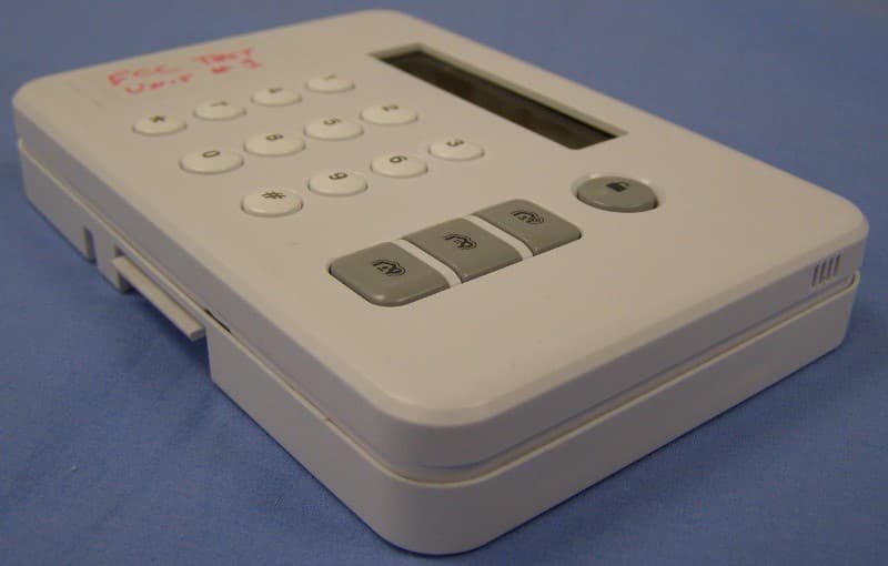
Click to zoom
Application Details
- Equipment Class
- DXT - Part 15 Low Power Transceiver, Rx Verified
- Date of Grant
- May 27, 2014
- Application Purpose
- Original Equipment
- Date of Application
- May 27, 2014
- Equipment Note
- Life Shield Keypad
- Frequency Range
- 345.00000000 - 345.00000000
- Company
- Nice North America LLC
- Country
- United States
Documents & Files
Document Text
Text extracted from the exhibit documents filed with the FCC. Open a document above to read the original.
Users Manual
Wireless Keypad SKP2 The SKP2 is a Wireless Keypad with Stay, Away, and Instant arming modes as well as panic emergency mode. The Keypad includes a display and status LED to indicate the current status of the system. The Keypad is powered by both batteries and an AC power adaptor model XXX. When the Keypad is operating from AC power, the display and backlight may operate continuously. When the Keypad is operating from only battery power, the display and backlight will only operate while in use (i.e. while pressing keys and for 20 seconds thereafter). Installation and Mounting The Keypad must be used within good communications range of the Security Base. While range varies with house construction, it is generally sufficient if the Keypad is within 30 to 50 feet of the Base. The Keypad may be wall mounted or table top mounted. The Keypad includes 2 AA batteries installed with plastic insulating tabs. To remove the tabs, first remove the back mounting plate by lifting on the snap (figure 1). Pull on the tab for each battery, making sure that the batteries remain in place. If the batteries must be replaced, follow the marked battery polarity (figure 2). For table top placement, re-install the back mounting plate by first inserting the tabs at top of the mounting plate and then re-snapping the bottom of the mounting plate. Snapping is easier if you simultaneously lift on the snap while pressing down on the mounting plate. This lifts the snap over the small detent. Next, snap the table stand onto the back housing. Make sure the table stand is oriented as shown with the flexible tabs aligned towards the top of the Keypad (figure 3). First insert the top tabs of the table stand into the back housing. Then apply pressure to the bottom tabs until the bottom tabs can be inserted into the bottom housing. For wall mount, first consider whether you plan on using the AC power adaptor. If using the AC power adaptor, next consider how you plan to route the cord. It may be routed through the wall or hang down the wall. (a) If through the wall, the cord must be routed through the opening in the back housing. In this case, first make your hole in the wall at the desired height. Mount the back housing to the wall with the tabs up and the snap down, using the screws provided, aligning the holes in the wall and the back housing. (figure 4). Route the cord through the wall and back housing, and insert the power connector into the plug on rear of Keypad. (b) If down the wall, the cord is routed through the channel on rear of Keypad. Next attach Keypad to the back housing by first inserting the tabs at top of the mounting plate and then re- snapping the Keypad to the bottom of the mounting plate. Snapping is easier if you simultaneously press on the snap while pressing down on the Keypad. Programming Your LifeShield system can support up to [4] Keypads in a single system. Each Keypad must be registered into the system before use. The Keypad shipped with your Security Base was pre-registered before shipment. Additional Keypads may be registered by using your Security Tablet, LifeShield web portal, or LifeShield mobile application (collectively “apps”). To register a Keypad, enter the Settings tab of the respective apps, and select Add Device. Follow the on-screen prompts. When prompted, press the following keys simultaneously on the Keypad “1-3-7-9” for 2 seconds. The Base will respond with audio confirmation and the apps will show a success message. If the Keypad fails to register with the Base, the apps will show a failure message. Possible causes of registration failure include: Keypad not powered, wrong keys pressed, Keypad out of range with Base, or too many Keypads already registered in LifeShield System. Using the Keypad If the Keypad is AC powered, the display, backlight, and LED will remain on continuously. If you do not want the backlight on continuously, press the following keys simultaneously on the Keypad “1-3-4” for 2 seconds. This will show a menu option to control backlight ON/OFF. If the Keypad is battery powered, the Keypad will sleep within 30 seconds after the last key has been pressed. The next time you press a key, the Keypad must obtain system status from the Security Base. This status update may take 2 to 5 seconds to receive, and then the display and LED will show current LifeShield system status. After you send a command to the Security Base, the Keypad must obtain new system status. This will again take 2 to 5 seconds, and then the display and LED will update to the new status. To arm your LifeShield system using the Keypad, press one of Away, Stay, or Instant keys and then enter your 4 digit code. After you have entered 4 digits, the Keypad will send the arm command to the System Base. If you have turned on One-Touch Arming in the System Settings (using one of the apps), then a 4 digit code is not required. To use One-Touch Arming, press and hold one of Away, Stay, or Instant keys and the Keypad will send the arm command. Note that you may only arm your system if current status is Ready to Arm. To disarm your LifeShield system, press the Off key then enter your 4 digit code. If at any time, you enter wrong digits and need to re-start, simply press the desired arming key or Off, and then your code. If you entered an invalid code, the System Base will update the Keypad display. To use the panic mode, simultaneously press and hold the * and # buttons. System Messages The Keypad can display messages in either English or Spanish. To change language, press the following keys simultaneously on the Keypad “3-7” for 2 seconds. This will show a menu option to control language. The Keypad includes the following messages (to be updated): ENGLISH SPANISH LED color (not all messages have an LED color) Decription READY TO ARM PREPARADO Solid Green NOT READY TO ARM NO ESTÁ PREPARADO Flashing Green DISARMED DESACTIVADO ARMED AWAY ACTIVADO PARA SALIR Blue ARMED STAY ACTIVADO PARA ESTAR Blue ARMED INSTANT…
Text truncated - open the document above for the full version.
Attestation Statements
LINEAR LLC 1950 CAMINO VIDA ROBLE, SUITE 150, CARLSBAD, CA 92008-6517 PHONE (760) 438-7000 ● (800) 421-1587 ● ENG. FAX (760) 438-7043 MAIL: P.O. BOX 9003 ● CARLSBAD, CA 92018-9003 _____________ CETCB 114 Olinda Drive Brea, California 92823 Gentlemen: We, Linear LLC, would like to declare that the application being submitted for the device with FCC ID: _________, has not been submitted to another TCB or FCC for certification. Sincerely, Josh Hansen Regulatory Engineer
Cover Letter(s)
LINEAR LLC 1950 CAMINO VIDA ROBLE, SUITE 150, CARLSBAD, CA 92008-6517 PHONE (760) 438-7000 ● (800) 421-1587 ● ENG. FAX (760) 438-7043 MAIL: P.O. BOX 9003 ● CARLSBAD, CA 92018-9003 _____________ CETCB 114 Olinda Drive Brea, California 92823 Gentlemen: We, Linear LLC, would like to request that all schematics, block diagrams, and operational descriptions submitted with the application for certification be withheld from public disclosure as per Section 0.459 of FCC Rules. This request is made under the provisions of Section 0.457 (d) of the Commission’s Rules, and Section 552 (b)(4) of the Freedom of Information Act. These sections authorize the withholding from public inspection, those materials which would be privileged as a matter of law if retained by the person submitting them, and materials which would not customarily be released to the public by that person. If you have any questions, please feel free to give me a call at (760) 438-7179 Sincerely, Josh Hansen Regulatory Engineer
ID Label/Location Info
LABEL,FCC,KEYPAD,LIFESHIELD LINEAR P/N:236824 X5 INK: PERMANENT BLACK MATERIAL: 60 LB. WHITE COATED, ADHESIVE BACKED SCALE: 1-1 This device complies with FCC Part 15 regulations. Operation is subject to the following two conditions: (1) This device may not cause harmful interference and (2) this device must accept any interference received, including interference that may cause undesired operation. FCC ID: EF400122 IC: 1078A-00122 Model: SKP2 LIFESHIELD LLC Made in China Power: 5VDC 200mA – + 236824 X5 1.312" .700"
ID Label/Location Info
REVISIONS REV DESCRIPTION DATE APPROVED X1 INITIAL RELEASE 02/25/2014 X2 ADD FCC LABEL 04/11/2014 X3 CHG FCC LABEL POSITION 04/21/2014 SEE SEPARATE PARTS LIST SEE SEPARATE PARTS LIST TBD TOLERANCES: UNLESS OTHERWISE NOTED ALL DIMENSIONS ARE INCHES [MM]: DECIMALS ANGLES: ± 0.5° CONCENTRICITY:±.005 [.13] A 8 B 76 5 C 8 (UNLESS OTHERWISE SPECIFIED) D NOTES: 76 5 D DO NOT SCALE DRAWING FINISH: MATERIAL: 4 APPROVED:APPROVED:APPROVED:APPROVED:CAD OPERATOR: PROJECT: CHECKED: 3 DATE 2 DATE DATE DATE DATE DATE A SCALE: SIZE: DRAWING NO.: TITLE: SHEET: 1 REV.: B 43 2 CD 1 1 OF 1 FLATNESS: ±.005 [.13]ROUNDNESS:±.005 [.13] .XXX±.005 [.13] .XX±.01 [.3] NONE ASSY,MECH,KEYPAD,LIFE SHIELD 236171 X3 M. SHIN 2/25/2014 TBDTBD TBDTBD TOLERANCES: UNLESS OTHERWISE NOTED ALL DIMENSIONS ARE INCHES [MM]: DECIMALS ANGLES: ± 0.5° CONCENTRICITY:±.005 [.13] A 8 B 76 5 C 8 (UNLESS OTHERWISE SPECIFIED) D NOTES: 76 5 D DO NOT SCALE DRAWING FINISH: MATERIAL: 4 APPROVED:APPROVED:APPROVED:APPROVED:CAD OPERATOR: PROJECT: CHECKED: 3 DATE 2 DATE DATE DATE DATE DATE A SCALE: SIZE: DRAWING NO.: TITLE: SHEET: 1 REV.: B 43 2 CD 1 1 OF 1 FLATNESS: ±.005 [.13]ROUNDNESS:±.005 [.13] .XXX±.005 [.13] .XX±.01 [.3] NONE ASSY,MECH,KEYPAD,LIFE SHIELD 236171 X3 M. SHIN 2/25/2014 TBDTBD TBD 1 ADHERE GASKET (ITEM 6) TO FR ONT PANEL (ITEM 2) AS SHOWN. 2 APPLY LABEL (ITEM 7) APPROXIMATELY WHERE SHOWN. 6 2 5 3 LABEL PLACEMENT DETAIL 7 2 (3) ASSEMBLED VIEW
Test Report
Report Number: D40522R1 FCC ID: EF400122 FCC Part 15 Subpart B & C Section 15.231 Test Report Brea Division 114 Olinda Drive Brea, CA 92823 (714) 579-0500 Agoura Division 2337 Troutdale Drive Agoura, CA 91301 (818) 597-0600 Silverado Division 19121 El Toro Road Silverado, CA 92676 (949) 589-0700 Lake Forest Division 20621 Pascal Way Lake Forest, CA 92630 (949) 587-0400 Page 1 of 18 FCC PART 15 SUBPART B & C TEST REPORT for LIFE SHIELD KEYPAD Model: SKP2 Prepared for LINEAR, LLC. 1950 CAMINO VIDA ROBLE, SUITE 150 CARLSBAD, CA 92008 Prepared by:_____________________ MATT HARRISON Approved by:____________________ JEFF KLINGER COMPATIBLE ELECTRONICS INC. 20621 PASCAL WAY LAKE FOREST, CALIFORNIA 92630 (949) 587-0400 DATE: MAY 22, 2014 REPORT APPENDICES TOTAL BODY A B C D E PAGES 18 2 2 2 15 23 62 This report shall not be reproduced except in full, without the written approval of Compatible Electronics. Report Number: D40522R1 FCC ID: EF400122 FCC Part 15 Subpart B & C Section 15.231 Test Report Brea Division 114 Olinda Drive Brea, CA 92823 (714) 579-0500 Agoura Division 2337 Troutdale Drive Agoura, CA 91301 (818) 597-0600 Silverado Division 19121 El Toro Road Silverado, CA 92676 (949) 589-0700 Lake Forest Division 20621 Pascal Way Lake Forest, CA 92630 (949) 587-0400 Page 2 of 18 TABLE OF CONTENTS Section / Title PAGE GENERAL REPORT SUMMARY 4 SUMMARY OF TEST RESULTS 5 1. PURPOSE 6 2. ADMINISTRATIVE DATA 7 2.1 Location of Testing 7 2.2 Traceability Statement 7 2.3 Cognizant Personnel 7 2.4 Date Test Sample was Received 7 2.5 Disposition of the Test Sample 7 2.6 Abbreviations and Acronyms 7 3. APPLICABLE DOCUMENTS 8 4. DESCRIPTION OF TEST CONFIGURATION 9 4.1 Description of Test Configuration 9 4.1.1 Photograph Test Configuration 9 4.1.2 Cable Construction and Termination 10 5. LISTS OF EUT, ACCESSORIES AND TEST EQUIPMENT 11 5.1 EUT and Accessory List 11 5.2 EMI Test Equipment 12 6. TEST SITE DESCRIPTION 13 6.1 Test Facility Description 13 6.2 EUT Mounting, Bonding and Grounding 13 6.3 Facility Environmental Characteristics 13 7. CHARACTERISTICS OF THE TRANSMITTER 14 7.1 Channel Number and Frequencies 14 7.2 Antenna 14 8. TEST PROCEDURES 15 8.1 RF Emissions 15 8.1.1 Conducted Emissions Test 15 8.1.2 Radiated Emissions (Spurious and Harmonics) Test 16 8.1.3 Fundamental Field Strength 17 8.1.4 Occupied Bandwidth 17 8.1.5 Transmit Time Out 17 8.1.6 Duty Cycle 17 9. TEST PROCEDURE DEVIATIONS 18 10. CONCLUSIONS 18 Report Number: D40522R1 FCC ID: EF400122 FCC Part 15 Subpart B & C Section 15.231 Test Report Brea Division 114 Olinda Drive Brea, CA 92823 (714) 579-0500 Agoura Division 2337 Troutdale Drive Agoura, CA 91301 (818) 597-0600 Silverado Division 19121 El Toro Road Silverado, CA 92676 (949) 589-0700 Lake Forest Division 20621 Pascal Way Lake Forest, CA 92630 (949) 587-0400 Page 3 of 18 LIST OF APPENDICES APPENDIX TITLE A Laboratory Accreditations and Recognitions B Modifications to the EUT C Additional Models Covered Under This Report D Diagrams, Charts, and Photos Test Setup Diagrams Antenna and Amplifier Factors Radiated Emissions Photos E Radiated Emissions Data Sheets LIST OF FIGURES FIGURE TITLE 1 Plot Map And Layout of Test Site Below 1GHz 2 Plot Map And Layout of Test Site Above 1GHz 3 Conducted Emissions Test Setup Report Number: D40522R1 FCC ID: EF400122 FCC Part 15 Subpart B & C Section 15.231 Test Report Brea Division 114 Olinda Drive Brea, CA 92823 (714) 579-0500 Agoura Division 2337 Troutdale Drive Agoura, CA 91301 (818) 597-0600 Silverado Division 19121 El Toro Road Silverado, CA 92676 (949) 589-0700 Lake Forest Division 20621 Pascal Way Lake Forest, CA 92630 (949) 587-0400 Page 4 of 18 GENERAL REPORT SUMMARY This electromagnetic emission test report is generated by Compatible Electronics Inc., which is an independent testing and consulting firm. The test report is based on testing performed by Compatible Electronics personnel according to the measurement procedures described in the test specifications given below and in the "Test Procedures" section of this report. The measurement data and conclusions appearing herein relate only to the sample tested and this report may not be reproduced in any form unless done so in full with the written permission of Compatible Electronics. This report must not be used to claim product endorsement by NVLAP, NIST, or any other agency of the U.S. Government or other governments. Device Tested: Life Shield Keypad Model: SKP2 S/N: N/A Product Description: The Life Shield Keypad is a Keypad for arming, disarming, and programming a home security system. Modifications: The EUT was not modified during testing. Manufacturer: Linear, LLC. 1950 Camino Vida Roble, Suite 150 Carlsbad, CA 92008 Test Date: May 1 st , 2 nd , 14 th , and 22 nd , 2014 Test Specifications: EMI requirements CFR Title 47, Part 15 Subpart B Sections 15.109 CFR Title 47, Part 15 Subpart C Sections 15.205, 15.209 and 15.231 Test Procedure: ANSI C63.4 ANSI C63.10 Report Number: D40522R1 FCC ID: EF400122 FCC Part 15 Subpart B & C Section 15.231 Test Report Brea Division 114 Olinda Drive Brea, CA 92823 (714) 579-0500 Agoura Division 2337 Troutdale Drive Agoura, CA 91301 (818) 597-0600 Silverado Division 19121 El Toro Road Silverado, CA 92676 (949) 589-0700 Lake Forest Division 20621 Pascal Way Lake Forest, CA 92630 (949) 587-0400 Page 5 of 18 SUMMARY OF TEST RESULTS TEST DESCRIPTION RESULTS 1 Conducted RF Emissions, 150 kHz - 30 MHz. Complies with the limits of CFR Title 47 Part 15 Subpart B Section 15.107 and Part 15 Subpart C Section 15.207 2 Radiated RF Emissions & Harmonics, 9 kHz – 4 GHz. Complies with the limits of CFR Title 47 Part 15 Subpart B Section 15.109 and Part 15 Subpart C Section 15.205, 15.209, and 15.231. SIX HIGHEST RADIATED EMISSIONS READINGS Reading Type (PK / QP / AV) Polarization (Vert / Horz) Frequency (MHz) Level (dBμV/m) Limit (dBμV/m) Delta (dB) Test Distance 1 AV V 345.00 70.46 77.26 -6.80 3-Meters 2 AV H 345.00 63.21 77.26 -14.05 3-Meters 3 QP V 37.70 2…
Text truncated - open the document above for the full version.
Contact Information
Applicant
Josh Hansen(Engineering Manager, Regulatory & Compliance)
Technical Contact
Compatible Electronics, Inc.Matt U Harrison
[email protected]949-587-0400
20621 Pascal Way · Lake Forest, California · United States
Test Firm
Compatible Electronics, Inc.Michael Christensen
Technical Specifications
| # | Rule Parts | Frequency Range | Power Output |
|---|---|---|---|
| 1 | 15C | 345 MHz - 345 MHz | - |
Other Applications from Nice North America LLC
EF400267
May 19, 2026Edge II Security Panel
Equipment Class
DSS - Part 15 Spread Spectrum TransmitterEF400266
Mar 12, 2026Wireless KVM Extender TX+RX
Equipment Class
NII - Unlicensed National Information Infrastructure TXEF400265
Mar 12, 2026Wireless KVM Extender TX+RX
Equipment Class
NII - Unlicensed National Information Infrastructure TXEF4-FGS223US
Dec 18, 2025DoubleDimmer-Control
Equipment Class
DXX - Part 15 Low Power Communication Device TransmitterEF400247
Jul 01, 2024Digital Transmitter
Equipment Class
DSS - Part 15 Spread Spectrum Transmitter