EF400128Garage Door Opener Remote Command Transceiver
Nice North America LLC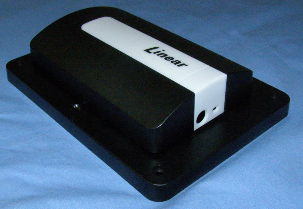
Click to zoom
Application Details
- Equipment Class
- DXT - Part 15 Low Power Transceiver, Rx Verified
- Date of Grant
- Mar 10, 2015
- Application Purpose
- Original Equipment
- Date of Application
- Mar 10, 2015
- Equipment Note
- Garage Door Opener Remote Command Transceiver
- Frequency Range
- 908.40000000 - 916.00000000
- Company
- Nice North America LLC
- Country
- United States
Documents & Files
Document Text
Text extracted from the exhibit documents filed with the FCC. Open a document above to read the original.
Users Manual
GD00Z-4GARAGE DOOR OPENERREMOTE COMMANDTRANSCEIVERwith TILT SENSORInstallation Instructions ➊ PRODUCT DESCRIPTION ➋ SAFETY NOTES ➌ PRODUCT COMPONENTS ➍ TILT SENSOR INSTALLATION AND BATTERY ➎ PAIRING (INCLUDING) WITH THE SYSTEM PRINTER’S INSTRUCTIONS: INSTR,INSTL,GD00Z-4 - P/N: 236956 AX4 - INK: BLACK - MATERIAL: 20 LB. MEAD BOND - SIZE: 11.000” X 8.500” - TOL. +/-.125" - SCAL E: 1-1 - FOLDING: 2-FOLD ALTERNATE - SIDE 1 OF 2 WARNING This operator system is equipped with an unattended operation feature. This door could move unexpectedly. NO ONE SHOULD CROSS THE PATH OF A MOVING DOOR! WARNING This system can be installed on sectional type (roll up) doors only per (UL-325). DO NOT INSTALL ON ONE-PIECE DOORS! WARNING Do not install the Remote Command Transceiver on garage door operators manufactured prior to 1993 (models without an operational safety beam entrapment detection system). WARNING The Remote Command Transceiver must be mounted in the garage, in sight of the garage door, where the visual and audible movement warning indicators can be clearly seen and heard. GD00Z-4 POWER INPUT JACK WARNING LIGHT LINK BUTTON CONNECTION WIRES MOUNTING SCREWS AND ANCHORS FOR GD00Z-4 POWER SUPPLY TILT SENSOR STATUS INDICATOR OPTIONAL ADJUSTABLE GD00Z-4 MOUNTING BRACKET POWER SUPPLY RETAINING BRACKET SCREWS AND MOUNTING TAPE FOR TILT SENSOR SCREW AND MOUNTING HARDWARE FOR ADJUSTABLE BRACKET SCREW FOR POWER SUPPLY BRACKET WIRE TIES TO INCLUDE THE GD00Z-4INTO YOUR CONTROLLER 1 2 WALL OUTLET POWER SUPPLY POWER INPUT JACK LINK BUTTON GD00Z-4 Press and release the link buttonon the GD00Z-4. Note: Plug in the GD00Z-4near your Z-Wave Controllerfor these steps Place your Z-Wave Controller intoDiscovery or Include mode. TO EXCLUDE THE GD00Z-4 FROM YOUR CONTROLLER Confirm that the GD00Z-4 wasrecognized by your Z-Wave Controller. Refer to your Z-Wave Controllersinstructions for additional informationon including devices. 3 1 2 Press and release the link buttonon the GD00Z-4.Place your Z-Wave Controller intoExclude mode.Confirm that the GD00Z-4 wasexcluded by your Z-Wave Controller. Refer to your Z-Wave Controllersinstructions for additional informationon excluding devices. 3 CR2032 PLUS SIDE UP !!! The system will notify youwhen the battery is low,replace the battery witha type CR2032 coin cell Insert thebatteryinto thetransmitter To open the case, twista small screwdriverin case slot SLOT Use double sided tape or the two mounting screws supplied (drill 1/16" pilot holes if required) POST ON BOTTOM "UP" ARROWS Snap the sensor ontothe mounting plate To activate the tilt sensor,remove the battery protection pull strip 2 ARROWS ON PLATE & SENSOR POINT UP LOW BATTERY REPLACEMENT 1 2 1 3 Attach the mounting plateto the top panel of the door USA & Canada (800) 421-1587 & (800) 392-0123 (760) 438-7000 - Toll Free FAX (800) 468-1340 www.nortekcontrol.com GD00Z-4 Overview • A garage door opener remote command transceiver with built-in Z-Wave technology. • Allows remote operation of a garage door opener using Z-Wave controllers. • Acts as a Z-Wave repeater to improve communications within the Z-Wave mesh network. GD00Z-4 Summary of Operation • GD00Z-4 connects to the garage door opener’s pushbutton wall console terminals. • A wireless tilt sensor mounts on the garage door and reports the door’s position to the GD00Z-4. • GD00Z-4 responds to Z-Wave commands from Z-Wave controllers to open or close the garage door. • A warning indicator light fl ashes and a beeper sounds for 5 seconds before the door begins to move. • If the door does not completely open or close, a second open or close command can be sent after 30 seconds. • If the door does not completely open or close after the second attempt, the GD00Z-4 operation is suspended until a local garage door pushbutton is activated. Z-Wave Information • Z-Wave ® is a registered trademark of Sigma Designs Inc. and/or its subsidiaries. • Z-Wave is an Interoperable two-way RF mesh networking technology designed for use with a Z-Wave gateway/controller and other Z-Wave enabled devices. • Replication is the process of copying or transferring your Z-Wave network from one controller to another. • This is a Security enabled Z-Wave product and must be used with a Security enabled Z-Wave controller in order to fully utilize this product. As such, this device will not respond to Basic CC commands. • ASSOCIATION: The GD00Z-4 supports 1 Group with 1 Node. Group 1 must be assigned the Node ID of the controller to which unsolicited notifi cations from the GD00Z-4 will be sent. The Z-Wave controller should set this association automatically after inclusion. APPLIANCE CONTROLS ➏ GD00Z-4 MOUNTING ➐ GD00Z-4 CONNECTIONS ➑ SYSTEM OPERATION ➒ OPERATION NOTES 1. The warning light will fl ash and the warning beeper will sound for fi ve seconds before the door opener is activated. STAY CLEAR OF THE DOOR, AND DOOR OPENER. THEY ARE ABOUT TO MOVE! 2. If the door does not completely open or close after remote activation, the GD00Z-4 will allow user to try to operate the door one more time. If the second attempt fails, the GD00Z-4 will go into lock-out mode. See Note #3. 3. If the GD00Z-4 is in lock-out mode and will not accept remote commands, activate the door from the pushbutton wall console. 4. Once the GD00Z-4 has initiated the movement of the garage door, another command cannot be sent for 30 seconds. This eliminates the chance of “bouncing” the garage door and possibly damaging the garage door opener. ➓ TROUBLESHOOTING PROBLEM POSSIBLE CAUSE CORRECTIVE ACTION Unable to include in Z-Wave network. GD00Z-4 was not properly excluded from a previous Z-Wave network. 1. Reset the GD00Z-4 by pressing the LINK button 5 times. A quick beep followed by a longer beep will indicate the reset. The GD00Z-4 does not fl ash or beep when activated. No power to the GD00Z-4. 1. Make sure the power supply is plugged in securely to a live outlet. 2. Make sure the power cord is plugged in securely to the GD00Z-4. The GD00Z…
Text truncated - open the document above for the full version.
Attestation Statements
Access Control | Security & Home Automation | Health & Wellness | Home Technology 1950 Camino Vida Roble Suite 150 Carlsbad CA 92008 800.421.1587 www.nortekcontrol.com 02/24/2015 CETCB 114 Olinda Drive Brea, CA 92823 Gentlemen: This is a letter of authorization to accept Compatible Electronics, Inc., specifically including the employees of Compatible Electronics, as an Agent for Nortek Security & Control LLC, 1950 Camino Vida Roble Suite 150, Carlsbad CA 92008, for a period of one year, to sign applications before the Commission on our behalf, to make representations to you on our behalf, and to receive and exchange data between our company and the Commission in connection with certification of the following Nortek Security & Control LLC product: GARAGE DOOR OPENER REMOTE COMMAND TRANSCEIVER Model: GD00Z‐4 FCC ID: EF400128 Under FCC Docket Number 20780 and General Docket Number 80‐284 pursuant to Part 15 of FCC Rules and Regulations. Please also accept this letter as an attestation that neither Nortek Security & Control LLC nor any of its officers, directors, or persons holding 5% or more of the outstanding stock or shares, voting or non‐voting, have been denied federal benefits under section 5301 of the Anti‐Drug‐Abuse act of 1988.21 U.S.C. 853(a). In addition, Nortek Security & Control LLC will notify the Federal Communications Commission if, at any time, the situation changes causing Nortek Security & Control LLC to be denied federal benefits. If you have any questions or need additional information, please feel free to give me a call at (760) 438‐7179 Sincerely, Josh Hansen Regulatory Engineer
Attestation Statements
Access Control | Security & Home Automation | Health & Wellness | Home Technology 1950 Camino Vida Roble Suite 150 Carlsbad CA 92008 800.421.1587 www.nortekcontrol.com 02/24/2015 CETCB 114 Olinda Drive Brea, California 92823 Gentlemen: We, Nortek Security & Control LLC, would like to declare that the application being submitted for the device with FCC ID: EF400128, has not been submitted to another TCB or FCC for certification. Sincerely, Josh Hansen Regulatory Engineer
Attestation Statements
Access Control | Security & Home Automation | Health & Wellness | Home Technology 1950 Camino Vida Roble Suite 150 Carlsbad CA 92008 800.421.1587 www.nortekcontrol.com 03/05/2015 CETCB 114 Olinda Drive Brea, CA 92823 Gentlemen: This letter is to formally notify that the following modification(s) had been made to our Garage Door Controller Model # GD00Z‐4 during FCC certification testing, and will be implemented in production. Modification(s): 908.40 MHz PA Control Value: 0X0E 916.00 MHz PA Control Value: 0X16 If you have any questions or need additional information, please feel free to give me a call at (760) 438‐7179 Sincerely, Josh Hansen Regulatory Engineer
Cover Letter(s)
Access Control | Security & Home Automation | Health & Wellness | Home Technology 1950 Camino Vida Roble Suite 150 Carlsbad CA 92008 800.421.1587 www.nortekcontrol.com 02/24/2015 CETCB 114 Olinda Drive Brea, California 92823 Gentlemen: We, Nortek Security & Control LLC, would like to request that all schematics, block diagrams, and operational descriptions submitted with the application for certification be withheld from public disclosure as per Section 0.459 of FCC Rules. This request is made under the provisions of Section 0.457 (d) of the Commission’s Rules, and Section 552 (b)(4) of the Freedom of Information Act. These sections authorize the withholding from public inspection, those materials which would be privileged as a matter of law if retained by the person submitting them, and materials which would not customarily be released to the public by that person. If you have any questions, please feel free to give me a call at (760) 438‐7179 Sincerely, Josh Hansen Regulatory Engineer
Cover Letter(s)
Correspondence by Project Project Number: Correspondence NumberMemo EF400128-1 1) Please provide a certification contract. Certification Contract has been provided. 2) Please provide a diagram showing the location of the FCC ID label. A corrected FCC ID label has been provided. 3) The user manual does not have the entire compliance statement. Please provide a corrected user manual. A corrected Users Manual has been provided. 4) The block diagram submitted is not sufficient. As per section 2.1033(b)(5) of the FCC rules, the block diagram must show “the frequency of all oscillators used in the device. The signal path and frequency shall be indicated at each block. The tuning range(s) and intermediate frequency(ies) shall be indicated at each block.” A corrected Block Diagram has been provided. 5) The external photos do not show all of the sides. Please provide additional external photos. Correct External Photos have been provided. 6) The internal photos show an RF shield. Please show additional photos with the shield removed. Correct Internal Photos have been provided. 7) Please provide a modification attestation letter. Modification Attestation Letter has been provided. Untitled Documenthttp://www.celectronics.com/CorrespondenceByProject.asp?ProjectNum... 1 of 13/11/2015 7:36 AM
ID Label/Location Info
LABEL,FCC,GD00Z-4 LINEAR P/N: 236954 AX6 INK: PERMANENT BLACK MATERIAL: 60 LB. WHITE COATED, ADHESIVE BACKED SCALE: 1-1 NOTE: PRINTER AND MATERIAL MUST BE UL OR ETL RECOGNIZED NORTEK S&C LLC MODEL: GD00Z-4 FREQUENCY: 908 and 916 MHz FCC ID: EF400128 IC: 1078A-00128 INPUT: 12VDC 2A OUTPUT: CLASS 2, 30V MAX. 236954 AX6 2.500" 1.500" MADE IN CHINA For use with garage door operators complying with UL325, manufactured after 1993. This device complies with Part 15 of the FCC Rules and Industry Canada license exempt RSS Standard(s). Operation subject to the following two conditions: (1) This device may not cause harmful interference and (2) This device must accept any interference received, including interference that may cause undesired operation. Le présent appareil est conforme aux CNR d’Industrie Canada applicables aux appareils radio exempts de licence. L’exploitation est autorisée aux deux conditions suivantes : (1) l’appareil ne doit pas produire de brouillage, et (2) l’utilisateur de l’appareil doit accepter tout brouillage radioélectrique subi, même si le brouillage est susceptible d’en compromettre le fonctionnement. 3061503 Conforms to UL Std 325 Certified to CSA Std C22.2 No 247 FCC LABEL TXET TXET BACKSIDE
RF Exposure Info
This device FCC ID: is excluded from SAR testing by the following justification The maximum power that the transmitter is capable o f is 1.15 mW Applied duty cycle? no Using the following formula from section 4.3.1 of K DB 447498 at test separation distances ≤ 50 mm [(max. power of channel, including tune-up toleranc e, mW) / (min. test separation distance, mm)] * [ √ f(GHz)] Duty Cycle 11.00% Value 1-g (mW) 10-g (mW) 0.22 (118) 117 "Value" shall be ≤ 3.0 for 1-g SAR and ≤ 7.5 for 10-g extremity SAR 1-g power limit 10-g power limit 157 392 “source-based” time-averaging based on an inherent property or duty-cycle of a device is allowed. An e xample of this is the determination of exposure from a device that uses digital technology such as a time-division mu ltiple-access (TDMA) scheme for transmission of a EF400128 Max Peak Power (dBm) Min Separation distance (mm) Fre quency (Ghz) < 50mm power limits for above frequency and distanc e When the minimum test separation distance is < 5 mm , a distance of 5 mm according to 5) in section 4.1 is applied to determine SAR test exclusion. 0.916 5 0.61
Test Report
Report Number: D50219R1 FCC ID: EF400128 FCC Part 15 Subpart B & C Section 15.249 Test Report Brea Division 114 Olinda Drive Brea, CA 92823 (714) 579-0500 Agoura Division 2337 Troutdale Drive Agoura, CA 91301 (818) 597-0600 Silverado Division 19121 El Toro Road Silverado, CA 92676 (949) 589-0700 Lake Forest Division 20621 Pascal Way Lake Forest, CA 92630 (949) 587-0400 Page 1 of 18 FCC PART 15 SUBPART B & SUBPART C SECTION 15.249 TEST REPORT for GARAGE DOOR OPENER REMOTE COMMAND TRANSCEIVER Model: GD00Z-4 Prepared for NORTEK SECURITY & CONTROL 1950 CAMINO VIDA ROBLE, SUITE 150 CARLSBAD, CA 92008 Prepared by:_____________________ MATT HARRISON Approved by:____________________ JEFF KLINGER COMPATIBLE ELECTRONICS INC. 20621 PASCAL WAY LAKE FOREST, CALIFORNIA 92630 (949) 587-0400 DATE: FEBRUARY 20, 2015 REPORT APPENDICES TOTAL BODY A B C D E PAGES 18 2 2 2 15 23 62 This report shall not be reproduced except in full, without the written approval of Compatible Electronics. Report Number: D50219R1 FCC ID: EF400128 FCC Part 15 Subpart B & C Section 15.249 Test Report Brea Division 114 Olinda Drive Brea, CA 92823 (714) 579-0500 Agoura Division 2337 Troutdale Drive Agoura, CA 91301 (818) 597-0600 Silverado Division 19121 El Toro Road Silverado, CA 92676 (949) 589-0700 Lake Forest Division 20621 Pascal Way Lake Forest, CA 92630 (949) 587-0400 Page 2 of 18 TABLE OF CONTENTS Section / Title PAGE GENERAL REPORT SUMMARY 4 SUMMARY OF TEST RESULTS 5 1. PURPOSE 6 2. ADMINISTRATIVE DATA 7 2.1 Location of Testing 7 2.2 Traceability Statement 7 2.3 Cognizant Personnel 7 2.4 Date Test Sample was Received 7 2.5 Disposition of the Test Sample 7 2.6 Abbreviations and Acronyms 7 3. APPLICABLE DOCUMENTS 8 4. DESCRIPTION OF TEST CONFIGURATION 9 4.1 Description of Test Configuration 9 4.1.1 Photograph Test Configuration 9 4.1.2 Cable Construction and Termination 10 5. LISTS OF EUT, ACCESSORIES AND TEST EQUIPMENT 11 5.1 EUT and Accessory List 11 5.2 EMI Test Equipment 12 6. TEST SITE DESCRIPTION 13 6.1 Test Facility Description 13 6.2 EUT Mounting, Bonding and Grounding 13 6.3 Facility Environmental Characteristics 13 7. CHARACTERISTICS OF THE TRANSMITTER 14 7.1 Channel Number and Frequencies 14 7.2 Antenna 14 8. TEST PROCEDURES 15 8.1 RF Emissions 15 8.1.1 Conducted Emissions Test 15 8.1.2 Radiated Emissions (Spurious and Harmonics) Test 16 8.1.3 Fundamental Field Strength 17 8.1.4 Emissions Radiated Outside of the Fundamental Frequency Band 17 9. TEST PROCEDURE DEVIATIONS 18 10. CONCLUSIONS 18 Report Number: D50219R1 FCC ID: EF400128 FCC Part 15 Subpart B & C Section 15.249 Test Report Brea Division 114 Olinda Drive Brea, CA 92823 (714) 579-0500 Agoura Division 2337 Troutdale Drive Agoura, CA 91301 (818) 597-0600 Silverado Division 19121 El Toro Road Silverado, CA 92676 (949) 589-0700 Lake Forest Division 20621 Pascal Way Lake Forest, CA 92630 (949) 587-0400 Page 3 of 18 LIST OF APPENDICES APPENDIX TITLE A Laboratory Accreditations and Recognitions B Modifications to the EUT C Additional Models Covered Under This Report D Diagrams, Charts, and Photos Test Setup Diagrams Antenna and Amplifier Factors Radiated and Conducted Emissions Photos E Radiated and Conducted Emissions Data Sheets LIST OF FIGURES FIGURE TITLE 1 Plot Map And Layout of Test Site Below 1GHz 2 Plot Map And Layout of Test Site Above 1GHz 3 Conducted Emissions Test Setup Report Number: D50219R1 FCC ID: EF400128 FCC Part 15 Subpart B & C Section 15.249 Test Report Brea Division 114 Olinda Drive Brea, CA 92823 (714) 579-0500 Agoura Division 2337 Troutdale Drive Agoura, CA 91301 (818) 597-0600 Silverado Division 19121 El Toro Road Silverado, CA 92676 (949) 589-0700 Lake Forest Division 20621 Pascal Way Lake Forest, CA 92630 (949) 587-0400 Page 4 of 18 GENERAL REPORT SUMMARY This electromagnetic emission test report is generated by Compatible Electronics Inc., which is an independent testing and consulting firm. The test report is based on testing performed by Compatible Electronics personnel according to the measurement procedures described in the test specifications given below and in the "Test Procedures" section of this report. The measurement data and conclusions appearing herein relate only to the sample tested and this report may not be reproduced in any form unless done so in full with the written permission of Compatible Electronics. This report must not be used to claim product certification, approval or endorsement by NVLAP, NIST, or any agency of the federal government. Device Tested: Garage Door Opener Remote Command Transceiver Model: GD00Z-4 S/N: None Product Description: The EUT connects to the garage door openers pushbutton wall console terminals. A wireless tilt sensor mounts on the garage door and reports the door’s position to the GD00Z-4. GD00Z-4 responds to Z-Wave commands from Z-Wave controllers to open or close the garage door. A warning indicator light fl ashes and a beeper sounds for 5 seconds before the door begins to move. If the door does not completely open or close, a second open or close command can be sent after 30 seconds. Modifications: The EUT was modified in order to comply with specifications. Please see the list of modifications in Appendix B. Manufacturer: Nortek Security & Control 1950 Camino Vida Roble, Suite 150 Carlsbad, CA 92008 Test Date: February 19 & 20, 2015 Test Specifications: EMI requirements CFR Title 47, Part 15 Subpart B Sections 15.107, 15.109, Subpart C Sections 15.205, 15.207, 15.209 and 15.249 Test Procedure: ANSI C63.4 & C63.10 Report Number: D50219R1 FCC ID: EF400128 FCC Part 15 Subpart B & C Section 15.249 Test Report Brea Division 114 Olinda Drive Brea, CA 92823 (714) 579-0500 Agoura Division 2337 Troutdale Drive Agoura, CA 91301 (818) 597-0600 Silverado Division 19121 El Toro Road Silverado, CA 92676 (949) 589-0700 Lake Forest Division 20621 Pascal Way Lake Forest, CA 92630 (949) 587-0400 Page 5 of 18 SUMMARY OF TEST RESULTS TEST DESCRIPTION RESULTS 1 Conducted RF Emissions, 150 kHz - …
Text truncated - open the document above for the full version.
Contact Information
Applicant
Josh Hansen(Engineering Manager, Regulatory & Compliance)
Technical Contact
Compatible Electronics, Inc.Matt U Harrison
[email protected]949-587-0400
20621 Pascal Way · Lake Forest, California · United States
Test Firm
Compatible Electronics, Inc.Michael Christensen
Technical Specifications
| # | Rule Parts | Frequency Range | Power Output |
|---|---|---|---|
| 1 | 15C | 908.4 MHz - 916 MHz | - |
Other Applications from Nice North America LLC
EF400267
May 19, 2026Edge II Security Panel
Equipment Class
DSS - Part 15 Spread Spectrum TransmitterEF400266
Mar 12, 2026Wireless KVM Extender TX+RX
Equipment Class
NII - Unlicensed National Information Infrastructure TXEF400265
Mar 12, 2026Wireless KVM Extender TX+RX
Equipment Class
NII - Unlicensed National Information Infrastructure TXEF4-FGS223US
Dec 18, 2025DoubleDimmer-Control
Equipment Class
DXX - Part 15 Low Power Communication Device TransmitterEF400247
Jul 01, 2024Digital Transmitter
Equipment Class
DSS - Part 15 Spread Spectrum Transmitter