EF400180Carbon Monoxide Alarm
Nice North America LLC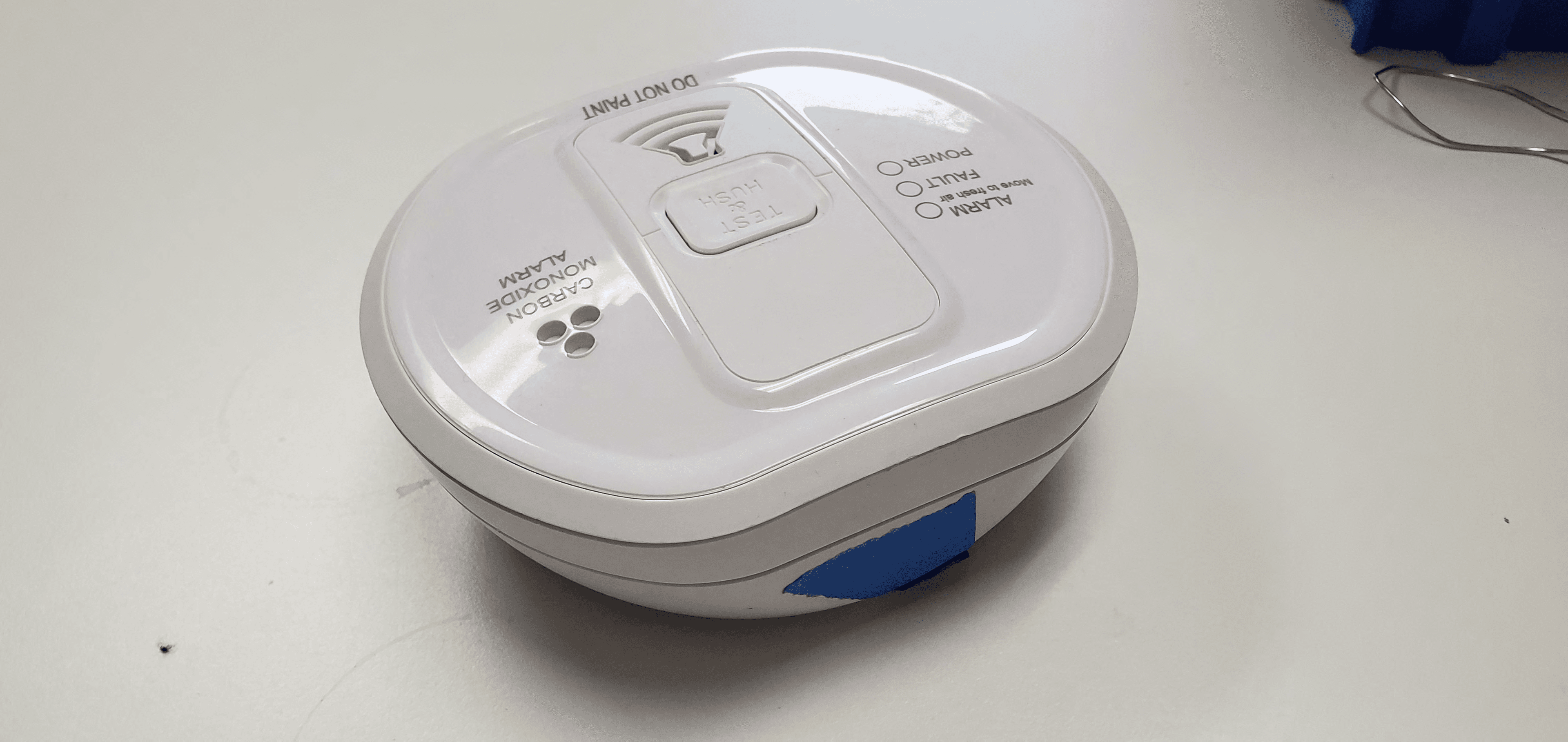
Click to zoom
Application Details
- Equipment Class
- DSC - Part 15 Security/Remote Control Transmitter
- Date of Grant
- Apr 07, 2020
- Application Purpose
- Original Equipment
- Date of Application
- Apr 07, 2020
- Equipment Note
- Carbon Monoxide Alarm
- Frequency Range
- 345.00000000 - 345.00000000
- Company
- Nice North America LLC
- Country
- United States
Documents & Files
Document Text
Text extracted from the exhibit documents filed with the FCC. Open a document above to read the original.
Users Manual
What happens when your CO Alarm detects Carbon Monoxide? When the CO Alarm detects potentially dangerous levels of CO, if flashes the red alarm light immediately and then sounds a loud alarm if the CO persists. Table 2 shows how the CO Alarm reacts to different levels of CO gas and exposure time. At higher levels of CO gas and exposure time. At higher levels of CO the Alarm turns on sooner. The rate of flashing of the red light indicates the level of CO. If your CO Alarm sounds follow the instructions in the “What to do when the Alarm Sounds” section of this manual. WARNING: NEVER IGNORE THE ALARM! Red Light (Pre-Alarm) Sounder (Alarm) CO Gas Level 0<ppm<30 ppmOff*Off > 50 ppm 1 flash every 3 secs on within 60 - 240 min (typical 90 min) > 110 ppm 2 flashes every 3 secs on within 10 - 50 min (typical 30 min) >250 ppm 3 flashes every 3 secs on within 4 - 15 min (typical 9 min) How to Tamper Proof the Alarm The 2GIG-CO8E-345 alarm can be made tamper proof. Break off the small pillar on the base of the CO Alarm (Figure 7). This will allow the tamper catch release to be activated and in the position shown in Figure 8. To remove Alarm from wall or ceiling it is now necessary to use a small flat tool (See Figure 9) to release the catch release. Follow the procedure for removing the alarm that is shown in Figure 10. If necessary it is possible to further tamper proof the Alarm by using a #2 or #4 1/4 inch self tapping screw (not included) and installing it into the indent of the mounting base (Figure 11). PILLAR FLAT BLADE TOOL Select a wall or ceiling location for the CO Alarm. Screw CO Alarm mounting base to wall or ceiling. Another alternative, if desired, is to allow the CO Alarm to free stand on a flat surface with the mounting base attached (See Figure 4). If locating the CO Alarm in a room with a fuel burning appliance: •If it is mounted on a wall, it should be located at a height greater than the height of any door or window but still be at least 6 inches from the ceiling. •If it is mounted on the ceiling it should be at least 12 feet from any wall or light fitting. •The CO Alarm should be a horizontal distance of between 3 feet and 9 feet from the potential CO source. •If there is a partition in the room, the CO Alarm should be located on the same side of the partition as the potential source. •In rooms with sloped ceilings, the CO Alarm should be located at the high side of the room. If locating the CO Alarm in a bedroom or in rooms remote from a fuel burning appliance: •Mount the CO Alarm relatively close to the breathing zone of the occupants. Whatever position is chosen make sure it is possible to view the three light indicators, when in the vicinity of the Alarm. WARNING: Do not use the CO Alarm on an intermittent basis, or as a portable detector for the leakage of combustion products from fuel burning appliances or chimneys. Test the CO Alarm weekly by pressing and holding the test button for a few seconds. Replace Alarm when the “REPLACE UNIT BY” date has been reached. Check the label on the side of the Alarm. Do not fit Alarm until all building work is completed to avoid contamination. Installation of CO Alarm/Wall or Ceiling Mounting Rotate CO alarm COUNTER CLOCKWISE to remove it from mounting plate. Placement of CO Alarm Ideally a Carbon Monoxide Alarm should be installed in: •Every room containing a fuel burning appliance. •Remote rooms where occupants spend a considerable amount of time. •Every bedroom. However if the number of Carbon Monoxide Alarms to be fitted is limited, the following points should be considered when deciding where best to fit the alarm(s): •If there is an appliance in a room where people sleep, place a CO Alarm in this room. •Locate a CO Alarm in a room containing a flueless or open-flued appliance, Locate an Alarm in a room where the occupant(s) spend most of their time (e.g. sitting room). •In a bedsite, the CO Alarm should be placed as far away from the cooking appliance as possible, but near to where the person sleeps. •If the appliance is in a room not normally used, such as a boiler room, the CO Alarm should be placed just outside the room so that the Alarm will be heard more easily. Suggested Alarm locations are shown in Figure 3. Verify that the package includes the following: •1―Wireless CO Alarm and Mounting Plate •2―Plastic wall anchors •2―Phillips Screws •3―AAA batteries (installed). Replace only with Duracell MN2400 Alkaline AAA size batteries (obtainable from local retailer). TEST & HUSH ALARM FA ULT PO WER CARBON MONO XIDE ALARM CO ALARM CO ALARM MOUNTING BASE ANCHORS (2) SCREWS (2) Installation Tools Required •Phillips Screw Driver •Variable Speed Drill with 1/16” Drill Bit •Flat Blade Tool (optional) CO Alarm Description and Function A. ALARM: Red LED B. FAULT: Amber LED C. POWER: Green LED D. Test/Hush Button GENERAL INFORMATION The Carbon Monoxide Alarm (2GIG-CO8E-345) is a battery powered wireless device for detecting the dangerous levels of Carbon Monoxide. It is one of the e-Series devices from Nortek Security and Control providing enhanced security with encrypted communications to the control panel using the 345Mhz frequency. The intended use is with compatible 2GIG wireless alarm systems. To know the maximum number of transmitters that can be supported, see the appropriate 2GIG Security System Installation Guide. IMPORTANT: This CO Alarm must be tested and maintained regularly following NFPA 720 requirements. This device is designed to protect individuals from the acute effects of carbon monoxide exposure. It will not fully safeguard individuals with specific medical conditions. If in doubt, consult a medical practitioner. It is intended for use in ordinary indoor locations of family living units. It is not designed to measure compliance with Occupational Safety and Health Administration (OSHA) commercial or industrial standards. ALARM FAULT POWER TEST & HUSH CARBON MONOXIDE ALARM A B C D What is Carbon Monoxide? Many people are …
Text truncated - open the document above for the full version.
Attestation Statements
Access Control | Security & Home Automation | Health & Wellness | Home Technology 5919 Sea Otter Pl #100 Carlsbad CA 92010 800.421.1587 www.nortekcontrol.com CETCB 114 Olinda Drive Brea, CA 92823 Gentlemen: This is a letter of authorization to accept Compatible Electronics, Inc., specifically including the employees of Compatible Electronics, as an Agent for Nortek Security & Control LLC, 5919 Sea Otter Pl Suite 100, Carlsbad CA 92010, for a period of one year, to sign applications before the Commission on our behalf, to make representations to you on our behalf, and to receive and exchange data between our company and the Commission in connection with certification of the following Nortek Security & Control LLC product: Model: FCC ID: Under FCC Docket Number 20780 and General Docket Number 80‐284 pursuant to Part 15 of FCC Rules and Regulations. Please also accept this letter as an attestation that neither Nortek Security & Control LLC nor any of its officers, directors, or persons holding 5% or more of the outstanding stock or shares, voting or non‐voting, have been denied federal benefits under section 5301 of the Anti‐Drug‐Abuse act of 1988.21 U.S.C. 853(a). In addition, Nortek Security & Control LLC will notify the Federal Communications Commission if, at any time, the situation changes causing Nortek Security & Control LLC to be denied federal benefits. If you have any questions or need additional information, please feel free to give me a call at (760)438‐7179 Sincerely, Torey Oliver Regulatory Engineer
Attestation Statements
Access Control | Security & Home Automation | Health & Wellness | Home Technology 5919 Sea Otter Pl #100 Carlsbad CA 92010 800.421.1587 www.nortekcontrol.com CETCB 114 Olinda Drive Brea, CA 92823 We, Nortek Security & Control LLC, would like to declare that the application being submitted for the device with FCC ID: , has not been submitted to another TCB or FCC for certification. Sincerely, Torey Oliver Regulatory Engineer
Attestation Statements
Access Control | Security & Home Automation | Health & Wellness | Home Technology 1950 Camino Vida Roble STE 150, Carlsbad CA, 92008 800.421.1587 www.nortekcontrol.com Federal Communications Commission Authorization and Evaluation Division 1435 Oakland Mills Road Columbia, MD 21046 Date: 12-9-2019 SUBJECT: FCC Application for (FCC ID: EF400180, Model: 2GIG-CO8E-345) This letter is to formally notify that the following modification(s) had been made to our Carbon Monoxide Detector, Model # 2GIG-CO8E-345, during FCC certification testing, and will be implemented in production. Modification(s): 1. Changed R9 to 68 Ohms If you have any questions or need additional information, please feel free to give me a call at (949) 395-1702. Sincerely, Torey Oliver Regulatory Engineer
Cover Letter(s)
Access Control | Security & Home Automation | Health & Wellness | Home Technology 5919 Sea Otter Pl #100 Carlsbad CA 92010 800.421.1587 www.nortekcontrol.com CETCB 114 Olinda Drive Brea, CA 92823 Gentlemen: We, Nortek Security & Control LLC, would like to request that all schematics, block diagrams, and operational descriptions submitted with the application for certification be withheld from public disclosure as per Section 0.459 of FCC Rules. This request is made under the provisions of Section 0.457 (d) of the Commission’s Rules, and Section 552 (b)(4) of the Freedom of Information Act. These sections authorize the withholding from public inspection, those materials which would be privileged as a matter of law if retained by the person submitting them, and materials which would not customarily be released to the public by that person. If you have any questions, please feel free to give me a call at (760) 438‐7179 Sincerely, Torey Oliver Regulatory Engineer
Cover Letter(s)
Access Control | Security & Home Automation | Health & Wellness | Home Technology 5919 Sea Otter Place, Suite 100, Carlsbad CA 92010 800.421.1587 www.nortekcontrol.com 9/3/2019 Federal Communications Commission 445 12th Street, SW Washington, DC 20554 Gentlemen: This is a letter of authorization to accept Torey Oliver of Nortek Security & Control LLC, to sign documentation on my behalf, make representations on my behalf, and to receive and exchange data in connection with FCC certification of all Nortek Security & Control LLC products on my behalf. If you have any questions or need additional information, please feel free to give me a call at (760) 438‐7179 Sincerely, Josh Hansen Engineering Manager, Regulatory & Compliance
ID Label/Location Info
D C B A 8 7 6 5 4 NOTES: {UNLESS OTHERWISE SPECIFIED) 1 MARK ASSEMBLY DASH NUMBER AND REVISION LE I I ER USING .12 [3.01 HIGH CHARACTERS, PERMANENT INK, CONTRAS11NG COLOR, APPROXIMATELY WHERE SHOWN. 2 3 INSTALL LABEL (ITEM 2) APPROXIMATELY WHERE SHOWN. INST ALL PULL TAB ( ITEM 3 ) ON CIRCUIT SIDE. J1 FlTS THROUGH SLOT IN TAB. PLACE ID LABEL ( ITEM 4) APPROXIMATELY WHERE SHOWN. 4. INCLUDE UNINSTALLED TXID LABEL ( ITEM 25 ) WITH PCB ASSEMBLY INSIDE THE SHIPPING BAG. THE LABEL WILL BE USED BY El ELECTRONICS ON THE F /G BOX. 5. FlNISHED ASSEMBLY TO BE ROHS COMPLJANT. 8 7 lHE INFORMATION CONTAINED IN lHIS DRAWING IS lHE SOLE PROPERTY OF NORTEK SECURITY & CONTROL ANY REPRODUCTION IN PART OR AS A WHOLE WllHOUT Wkl I I EN PERMISSION OF NORTEK SECURITY & CONTROL IS PROHIBITED. 6 UNI ESS OlHERWISE NOTED ALL DIMENSIONS ARE INCHES IMM1: TOLERANCES: 1 \ 2 DECIMALS ANGLES: + /-5 DEG .XX+/-. . 02 L51 ROUNDNESS:+/-.005 L131 .XXX+/- .005 L131 FLATNESS:+/-.005 L131 CONCENTRICITY:+ /-.005 L 131 MAIERIAL; FINISH: 5 4 3 2 1 REVISIONS REV DESCRIPllON DAlE APPROVED 1 -.. 1 0022497 REU FCC ID: EF4D0180 IC ID: 1078A-00180 X1 ENGINEERING RELEASE X2 EC0-024656 ' \ ,,, •••• ·� �� I ■ ••• 7,-. �)f V I TP I I� . � � :. 020 -i--i �U2��� s •,:_□--.. - � -- • :: C -1- 0 T= = :� N • • ■ ■ C3 CC = = ; -' •-• ■■ RS: = • r.r.ffi)■■1 ■■ C@ e ••r;r ... ••Ul • ■ ■ 1:1L I "" C2 •• J2 ■"■a • 00 C 6 TP11 Cl ; \ ! Ct 41- '-"-' u u C7 (%: I� l••I �::fl O RS �TP2 • l••l r ■ : :Ii..,� C15 c12l!, o:, m "' 'D a ee:ee: VIEW FROM COMPONENT SIDE 3 4 / 8 •••• 2J! 7 •••• 10022496 REU Xl NORTEK @ 2018 VIEW FROM CIRCUIT SIDE SEE SEP ARA 1E PARTS UST PROJECT: CAD OPERA TOR: DA TE TITLE: M. KINGSLEY 07 /23/18 CHECKED: DATE APPROVED: DATE APPROVED: DATE 3 SIZE: SCALE: NONE _,...,., NORTEK SECURITY & CONTROL ASSY, PCB, El 345 COS DRAWING NO.: DO NOT SCALE DRAWING 2 REV.: 10022497 X2 SHEET: 1 OF 1 1 D C B A The label is silkscreened onto the PCB with a permanent ink
RF Exposure Info
Compatible Electronics, Inc. https://celectronics.com 20621 Pascal Way Lake Forest, CA 92630 SAREXJUST-B-0-43D02/27/2020 This device FCC ID: Prepared By: Date: The maximum power that the transmitter is capable of is0.51mWApplied duty cycle?no Using the following formula from section 4.3.1 of KDB 447498at test separation distances ≤ 50 mm [(max. power of channel, including tune-up tolerance, mW) / (min. test separation distance, mm)] * [√f(GHz)] Duty Cycle 50.00% Value1-g (mW)10-g (mW) 0.06152535 "Value" shall be ≤ 3.0 for 1-g SAR and ≤ 7.5 for 10-g extremity SAR 1-g power limit10-g power limit 255638 EF400180 Max Peak Power (dBm)Min Separation distance (mm)*Frequency (Ghz) < 50mm power limits for above frequency and distance When the minimum test separation distance is < 5 mm, a distance of 5 mm according to 5) in section 4.1 is applied to determine SAR test exclusion. 0.3455-2.90 Howard Huang 3/26/20
Test Report
Report Number: D81128P1 FCC ID: EF400180 IC ID: 1078-00180 FCC Part 15 Subpart C Section 15.231, RSS GEN & RSS 210 Test Report 20621 PASCAL WAY, LAKE FOREST, CALIFORNIA, 92630 • PH: (949) 587-0400 FX: (949) 587-0476 Page 1 of 22 FCC PART 15 SUBPART C , SECTION 15.231 RSS GEN & RSS 210 TEST REPORT For CARBON MONOXIDE ALARM Model: 2GIG-CO8E-345 Prepared for NORTEK SECURITY & CONTROL 5919 SEA OTTER PL #100 CARLSBAD, CA 92010 Prepared by: _____________________ HOWARD HUANG Approved by: ____________________ JOEY MADLANGBAYAN COMPATIBLE ELECTRONICS INC. 20621 PASCAL WAY LAKE FOREST, CALIFORNIA 92630 (949) 587-0400 DATE: FEBRUARY 28, 2020 REPORT APPENDICES TOTAL BODY A B C D E PAGES 22 2 2 2 12 17 57 This report shall not be reproduced, except in full, without the written approval of Compatible Electronics. Report Number: D81128P1 FCC ID: EF400180 IC ID: 1078-00180 FCC Part 15 Subpart C Section 15.231, RSS GEN & RSS 210 Test Report 20621 PASCAL WAY, LAKE FOREST, CALIFORNIA, 92630 • PH: (949) 587-0400 FX: (949) 587-0476 Page 2 of 22 TABLE OF CONTENTS Section / Title PAGE GENERAL REPORT SUMMARY 4 SUMMARY OF TEST RESULTS 5 1. PURPOSE 6 2. ADMINISTRATIVE DATA 7 2.1 Location of Testing 7 2.2 Traceability Statement 7 2.3 Cognizant Personnel 7 2.4 Date Test Sample was Received 7 2.5 Disposition of the Test Sample 7 2.6 Abbreviations and Acronyms 7 3. APPLICABLE DOCUMENTS 8 4. DESCRIPTION OF TEST CONFIGURATION 9 4.1 Description of Test Configuration - EMI 9 5. LISTS OF EUT, ACCESSORIES AND TEST EQUIPMENT 13 5.1 EUT and Accessory List 13 5.2 EMI Test Equipment 14 5.3 Test Software 14 6. TEST SITE DESCRIPTION 15 6.1 Test Facility Description 15 6.2 EUT Mounting, Bonding and Grounding 15 6.3 Facility Environmental Characteristics 15 6.4 Measurement Uncertainty 15 7. CHARACTERISTICS OF THE TRANSMITTER 16 7.1 Channel Number and Frequencies 16 7.2 Antenna 16 7.3 EUT Test Software 16 8. TEST PROCEDURES 17 8.1 RF Emissions 17 9. TEST PROCEDURE DEVIATIONS 22 10. CONCLUSIONS 22 Report Number: D81128P1 FCC ID: EF400180 IC ID: 1078-00180 FCC Part 15 Subpart C Section 15.231, RSS GEN & RSS 210 Test Report 20621 PASCAL WAY, LAKE FOREST, CALIFORNIA, 92630 • PH: (949) 587-0400 FX: (949) 587-0476 Page 3 of 22 LIST OF APPENDICES APPENDIX TITLE A Laboratory Accreditations B Modifications to the EUT C Additional Models Covered Under This Report D Diagrams, Charts and Photos • Test Setup Diagrams • Antenna Factors • Radiated Emissions Photos E Data Sheets LIST OF FIGURES FIGURE TITLE 1 RADIATED EMISSIONS 3-METER SEMI -ANECHOIC TEST CHAMBER Report Number: D81128P1 FCC ID: EF400180 IC ID: 1078-00180 FCC Part 15 Subpart C Section 15.231, RSS GEN & RSS 210 Test Report 20621 PASCAL WAY, LAKE FOREST, CALIFORNIA, 92630 • PH: (949) 587-0400 FX: (949) 587-0476 Page 4 of 22 GENERAL REPORT SUMMARY This electromagnetic emission report is generated by Compatible Electronics Inc., which is an independent testing and consulting firm. The tes t report is based on testing performed by Compati ble Electronics personnel according to the measurement procedures described in the test specifications given below and in the "Test Procedures" section of this report. The measurement data and conclusions ap pearing herein relate only to the sample tested and this report may not be reproduced in any form except in full, without the written permission of Compatible Electronics. This report must not be used by the client to claim product certification, approval, or endorsement by NVLAP, NIST, or any agency of the federal government. Device Tested: Carbon Monoxide Alarm Model: 2GIG-CO8E-345 Product Description: The model 2GIG-CO8E-345 is a low power, microprocessor controlled, alarm sensor, and transmitter operating at a frequen cy of 345 MHz. Power is supplied by two replaceable Alkaline AAA 1.5V batteries in series to supply 3.0V to the circuit. (Dimensions: Radius 5” & 2.5” height). Modifications: The EUT was modified during the testing. Please see the list of modifications located in Appendix B. Manufacturer: Nortek Security & Control. 5919 Sea Otter #100 Carlsbad, CA 92010 Test Dates: November 28 & December 16, 2018 an d November 21 & December 1, 2019 and February 28, 2020. Test Specifications Covered by Accreditation : EMI requirements: CFR Title 47, Part 15 Subpart B and C Sections 15.205, 15.207, 15.209 & 15.231 RSS GEN & RSS 210. Test Procedure: ANSI C63.4: 2014 & ANSI C63.10: 2013. Report Number: D81128P1 FCC ID: EF400180 IC ID: 1078-00180 FCC Part 15 Subpart C Section 15.231, RSS GEN & RSS 210 Test Report 20621 PASCAL WAY, LAKE FOREST, CALIFORNIA, 92630 • PH: (949) 587-0400 FX: (949) 587-0476 Page 5 of 22 SUMMARY OF TEST RES U LT S TEST DESCRIPTION RESULTS 1 Conducted RF Emissions, 150 kHz - 30 MHz The EUT is battery powered; therefore, this test was deemed unnecessary and thus was not performed. 2 Radiated RF Emissions, 9 kHz – 3450 MHz Complies with the limits of CFR Title 47, Part 15 , Subpart B & C Section 15.209, 15.231 & RSS GEN 3 -20 dB and 99% Occupied Bandwidth of the Emission Complies with the limits of CFR Title 47, Part 15, Subpart C Section 15.231 & RSS 210. 4 Peak Radiated EMI Complies with the limits of CFR Title 47, Part 15, Subpart C Section 15.231 & RSS 210. 5 Transmit Timeout Complies with the limits of CFR Title 47, Part 15, Subpart C Section 15.231 & RSS 210. TABLE 1 SIX HIGHEST RADIATED EMISSIONS READINGS Reading Type (PK / QP / AV) Polarization (Vert / Horz) Frequency (MHz) Level (dBμV/m) Limit (dBμV/m) Delta (dB) Test Distance 1 AV H 345.00 74.92 77.26 -2.34 3-Meter 2 AV V 345.00 73.55 77.26 -3.71 3-Meter 3 PK H 345.00 92.32 97.26 -4.94 3-Meter 4 PK V 345.00 90.95 97.26 -6.31 3-Meter 5 AV V 345.00 69.83 77.26 -7.43 3-Meter 6 PK V 345.00 87.23 97.26 -10.03 3-Meter Report Number: D81128P1 FCC ID: EF400180 IC ID: 1078-00180 FCC Part 15 Subpart C Section 15.231, RSS GEN & RSS 210 Test Report 20621 PASCAL WAY, LAKE FOREST, CALIFORNIA, 92630 • PH: (949) 587-0400 FX: (949) 587-0476 Page 6 of 22 1. PURPOSE This document is a qu…
Text truncated - open the document above for the full version.
Contact Information
Applicant
Josh Hansen(Engineering Manager, Regulatory & Compliance)
Technical Contact
Compatible Electronics, Inc.Howard Huang
[email protected]949-587-0400
20621 Pascal Way · Lake Forest, California · United States
Test Firm
Compatible Electronics, Inc.Michael Christensen
Technical Specifications
| # | Rule Parts | Frequency Range | Power Output |
|---|---|---|---|
| 1 | 15.231 | 345 MHz - 345 MHz | - |
Other Applications from Nice North America LLC
EF400267
May 19, 2026Edge II Security Panel
Equipment Class
DSS - Part 15 Spread Spectrum TransmitterEF400266
Mar 12, 2026Wireless KVM Extender TX+RX
Equipment Class
NII - Unlicensed National Information Infrastructure TXEF400265
Mar 12, 2026Wireless KVM Extender TX+RX
Equipment Class
NII - Unlicensed National Information Infrastructure TXEF4-FGS223US
Dec 18, 2025DoubleDimmer-Control
Equipment Class
DXX - Part 15 Low Power Communication Device TransmitterEF400247
Jul 01, 2024Digital Transmitter
Equipment Class
DSS - Part 15 Spread Spectrum Transmitter