EF400207Transceiver Module
Nice North America LLC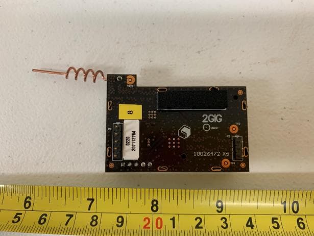
Click to zoom
Application Details
- Equipment Class
- DTS - Digital Transmission System
- Date of Grant
- Aug 10, 2020
- Application Purpose
- Original Equipment
- Date of Application
- Aug 10, 2020
- Equipment Note
- Transceiver Module
- Frequency Range
- 906.00000000 - 924.00000000
- Company
- Nice North America LLC
- Country
- United States
Documents & Files
Document Text
Text extracted from the exhibit documents filed with the FCC. Open a document above to read the original.
Users Manual
Copyright © 2020 Nortek Security & Control 10029872 Rev-B X1 2GIG-XCVR5e Transceiver Module PRODUCT DESCRIPTION The Model 2GIG-XCVR5e Transceiver Module is designed to be used with the 2GIG security system control panel. The transceiver is a dual frequency device. It receives 345 MHz signals from the system sensors, and receives and transmits 900 MHz signals to and from the Image Sensor 3. To use a Image Sensor 3 with the 2GIG GC2e security system control panel, the 2GIG-XCVR5e Transceiver Module must be installed into the control panel. The control panel must also be running firmware Version 1.23 or greater to function with the transceiver and Image Sensor. Check the current version number of the firmware using the control panel’s toolbox feature. If the control panel needs a firmware update, contact 2GIG for details on obtaining a compatible control panel or to receive an over-the-air update through the control panel’s cell radio (if the panel is cell radio equipped). COMPONENT LOCATIONSREMOVE POWER REMOVE EXISTING RECEIVERTRANSCEIVER INTO 3-PIN CONNECTORTRANSCEIVER INTO 5-PIN CONNECTORANTENNA PLACEMENT RECONNECT BATTERYTEST SYSTEMLIMITED WARRANTY This Nortek Security & Control LLC product is warranted against defects in material and workmanship for two (2) years. This warranty extends only to wholesale customers who buy direct from Nortek Security & Control LLC or through Nortek Security & Control LLC’s normal distribution channels. Nortek Security & Control LLC does not warrant this product to consumers. Consumers should inquire from their selling dealer as to the nature of the dealer’s warranty, if any. There are no obligations or liabilities on the part of Nortek Security & Control LLC for consequential damages arising out of or in connection with use or performance of this product or other indirect damages with respect to loss of property, revenue, or profit, or cost of removal, installation, or reinstallation. All implied warranties for functionality, are valid only until the warranty expires. This Nortek Security & Control LLC Warranty is in lieu of all other warranties expressed or implied. IMPORTANT!!! Radio controls provide a reliable communications link and fill an important need in portable wireless signaling. However, there are some limitations which must be observed. • For U.S. installations only: The radios are required to comply with FCC Rules and Regulations as Part 15 devices. As such, they have limited transmitter power and therefore limited range. • A receiver cannot respond to more than one transmitted signal at a time and may be blocked by radio signals that occur on or near their operating frequencies, regardless of code settings. • Changes or modifications to the device may void FCC compliance. • Infrequently used radio links should be tested regularly to protect against undetected interference or fault. • A general knowledge of radio and its vagaries should be gained prior to acting as a wholesale distributor or dealer, and these facts should be communicated to the ultimate users. This device complies with FCC Part 15 and Canada Rules and Regulations. Operation is subject to the following two conditions: (1) This device may not cause harmful interference and (2) this device must accept any interference received, including interference that may cause undesired operation. FCC/IC Statements RF Exposure Considerations This modular complies with FCC RF radiation exposure limits set forth for an uncontrolled environment. This transmitter must not be co-located or operating in conjunction with any other antenna or transmitter. RF Exposure - This device is only authorized for use in a mobile application. At least 20 cm of separation distance between the module and the user’s body must be maintained at all times. A label must be affixed to the outside of final commercial product with the following statements: This device contains FCC ID: EF400207 This device contains IC ID: 1078A-00207 Consistent with §2.909(a), the following text must be included within the user’s manual or operator instruction guide for the final commercial product. This modular complies with FCC RF radiation exposure limits set forth for an uncontrolled environment. This transmitter must not be co-located or operating in conjunction with any other antenna or transmitter. This device is only authorized for use in a mobile application. At least 20 cm of separation distance between the module and the user’s body must be maintained at all times. The final host/module combination may also need to be evaluated against the FCC Part 15B criteria for unintentional radiators in order to be properly authorized for operation as a Part 15 digital device. The FCC Part 15 Statement shall be included in the user manual of final commercial product if applicable. CAUTION: Any changes or modifications not expressly approved could void the user’s authority to operate the equipment or dial PRINTER’S INSTRUCTIONS: INSTR,XCVR5e,2GIG - LINEAR P/N: 10029872 Rev-B X1 - INK: BLACK - MATERIAL: 20 LB. MEAD BOND - SIZE: 11.000” X 8.500” - SCALE: 1-1 - SIDE 1 OF 2 900 MHZ ANTENNAA PLUG-IN TRANSCEIVERR MODULE FOAM PRESSURE PAD SHIELD THE ANTENNA PLACEMENT IS CRITICAL FOR PROPER OPERATIONN DO NOT BEND THE ANTENNA !!! IMPORTANT !!! BEFORE PROCEEDING, UN-PLUG THE AC POWER SUPPLY, OPEN THE CONTROL PANEL CASE, THEN DISCONNECT THE BACKUP BATTERY PULL UP ON THE PLUG-IN RECEIVER MODULE TO 5-PIN CONNECTOR 3-PIN CONNECTOR DISCONNECT IT FROM THE 5-PIN AND 3-PIN CONNECTORS CONTROL PANEL THE PLUG-IN RECEIVER MODULE IS LOCATED ON THE MAIN CIRCUIT BOARD, RIGHT BEHIND THE HOME BUTTON RECEIVER MODULE RE-CONNECT THE BATTERY, CLOSE THE CONTROL PANEL, THEN PLUG IN THE AC POWER SUPPLY PLACE THE CONSOLE IN PROGRAMMING MODE AND PREPARE IT FOR WIRELESS ZONE PROGRAMMING. REFER TO THE IMAGE SENSOR’S INSTALLATION GUIDE. 2GIG GC2e CONSOLE IMAGE SENSOR USE THE CONTROL PANEL'S TOOLBOX TO CHECK THE FIRMWARE VERSION IN THE CONTROL PANEL. THE FIRMWARE VERSION MUST…
Text truncated - open the document above for the full version.
Cover Letter(s)
Access Control | Security & Home Automation | Health & Wellness | Home Technology 5919 Sea Otter Place, Carlsbad CA, 92010 800.421.1587 www.nortekcontrol.com 7/14/2020 Federal Communications Commission Authorization and Evaluation Division 1435 Oakland Mills Road Columbia, MD 21046 SUBJECT: FCC Application for (FCC ID: EF400207) To Whom It May Concern: We, the undersigned, hereby authorize David Zhang of Vista Laboratories, Inc. located at 1261 Puerta Del Sol, San Clemente, CA 92673, to apply to the Federal Communications Commission on our behalf. Any and all acts carried out by Vista Laboratories, Inc. on our behalf shall have the same effect as acts of our own. This is to advise that we are in full compliance with the Anti- Drug Abuse Act. We, the applicant, are not subject to a denial of federal benefits pursuant to Section 5301 of the Anti-Drug Act of 1988, 21 USC853a, and no party to the application is subject to a denial of federal benefits pursuant to that section. Sincerely, Torey Oliver Engineer, Regulatory & Compliance Access Control | Security & Home Automation | Health & Wellness | Home Technology 5919 Sea Otter Place, Carlsbad CA, 92010 800.421.1587 www.nortekcontrol.com 7/14/2020 Federal Communications Commission Authorization and Evaluation Division 1435 Oakland Mills Road Columbia, MD 21046 SUBJECT: Confidentiality Request regarding application for certification of FCC ID: EF400207: To Whom It May Concern: We, Nortek Security & Control LLC, would like to request that all schematics, block diagrams, and operational descriptions submitted with the application for certification be withheld from public disclosure as per Section 0.459 of FCC Rules. This request is made under th e provision s of Section 0.457 (d) of th e Commission’s Rules, and Section 552 (b)(4) of the Freedom of Information Act. These sections authorize the withholding from public inspection, those materials which would be privileged as a matter of law if retained by the person submitting them, and materials which would not customarily be released to the public by that person. Sincerely, Torey Oliver Engineer, Regulatory & Compliance
Cover Letter(s)
Fed eral Communications Commission Authorization and Evaluation Division Confidentiality Request regarding application for certification of FCC ID: ________________ Pursuant to Sections 0.457 and 0.459 of the Commission’s Rules, we hereby request confidential treatment of information accompanying this application as outlined below: Type of Confidentiality Requested Exhibit Type ☐Short Term☐Permanent Block Diagrams ☐Short Term External Photos ☐Short Term☐Permanent* Internal Photos ☐Short Term☐Permanent Operation Description ☐Short Term☐Permanent Parts List/BOM ☐Short Term☐Permanent Schematics ☐Short Term Test Setup Photos ☐Short Term☐Permanent* User manual *Requires further justification before permanent confidentiality will be allowed. The above materials contain trade secrets and proprietary information not customarily released to the public. The public disclosure of these materials may be harmful to the applicant and provide unjustified benefits to its competitors. Permanent Confidentiality: The applicant requests the exhibits listed above as permanently confidential be withheld from public review due to materials that contain trade secrets and proprietary information not customarily released to the public. Short-Term Confidentiality: Pursuant to DA04-1705 June 15, 2004 of the Commission’s public notice, we also request temporary confidential treatment of information accompanying this application as outlined below for an initial period of ____________ days. Sincerely, Client’s signature: ________________________________ Client’s name & title: _____________________________ Access Control | Security & Home Automation | Health & Wellness | Home Technology 5919 Sea Otter Pl. #100, Carlsbad CA, 92008 (760) 438-7000 www.nortekcontrol.com
Cover Letter(s)
Modular Approval Letter FCC ID : , is seeking FCC Authorization as a Single Modular transmitter / Single Limited Modular Approval (please check one) The EUT meets the requirements for: Single Modular approval / Single Limited Modular Approval (please check one) as detailed in KDB 996369. Compliance to each of the requirements is described below: Modular Approval Requirement Yes No Please provide a detailed explanation if the answer is “No.” (i) The radio elements of the modular transmitter must have their own shielding. The physical crystal and tuning capacitors may be located external to the shielded radio elements. X (ii) The modular transmitter must have buffered modulation/data inputs (if such inputs are provided) to ensure that the module will comply with part 15 requirements under conditions of excessive data rates or over-modulation. X (iii) The modular transmitter must have its own power supply regulation. X (iv) The modular transmitter must comply with the antenna and transmission system requirements of §§ 15.203, 15.204(b) and 15.204(c). The antenna must either be permanently attached or employ a ‘‘unique’’ antenna coupler (at all connections between the module and the antenna, including the cable). The ‘‘professional installation’’ provision of § 15.203 is not applicable to modules but can apply to limited modular approvals under paragraph (b) of this section. X (v) The modular transmitter must be tested in a stand-alone configuration X (vi) The modular transmitter must be equipped with either a permanently affixed label or must be capable of electronically displaying its FCC identification number. X (vii) The modular transmitter must comply with any specific rules or operating requirements that ordinarily apply to a complete transmitter and the manufacturer must provide adequate instructions along with the module to explain any such requirements. A copy of these instructions must be included in the application for equipment authorization. X (viii) The modular transmitter must comply with any applicable RF exposure requirements in its final configuration. X Client’s signature: ________________________________ Client’s name & title: _____________________________ Contact information / address:
External Photos
EUT Top View EUT Bottom View
ID Label/Location Info
Ac cess Control | Security & Home Automation | Health & Wellness | Home Technology 5919 Sea Otter Pl. #100, Carlsbad CA, 92008 (760) 438-7000 www.nortekcontrol.com Label and Location Label is to be silkscreened onto the PCB.
Internal Photos
Access Control | Security & Home Automation | Health & Wellness | Home Technology 5919 Sea Otter Pl. #100, Carlsbad CA, 92008 (760) 438-7000 www.nortekcontrol.com Label and Location Label is to be silkscreened onto the PCB.
RF Exposure Info
FCC MPE Evaluation (FCC ID: EF400207) RF Exposure Requirements: 47 CFR §1.1307(b) RF Radiation Exposure Limits: 47 CFR §1.1310 RF Radiation Exposure Guidelines: FCC OST/OET Bulletin Number 65 EUT Frequency Band: 902 – 924 MHz Limits for General Population/Uncontrolled Exposure in the band of: 300 - 1500 MHz, Power Density Limit: f/1500 mW/cm2 Limits for General Population/Uncontrolled Exposure in the band of: 1500 - 100,000 MHz Power Density Limit: 1 mW / cm 2 Equation: S = PG / 4R 2 or R = √PG / 4S Where, S = Power Density P = Power Input to Antenna G = Antenna Gain R = distance to the center of radiated antenna ____________________________________________________________________________________________________________ Prediction distance 20 cm Radio Frequency (MHz) Max Conducted Output Power (dBm) Antenna Gain (dBi) Separation distance (cm) Power Density (mW/ cm 2 ) MPE Limit (mW/ cm 2 ) 900MHz radio 906 - 924 10.105 2 20 0.003 0.604 The above results show that the device complies with the MPE requirement. Completed By: David Zhang Vista Laboratories, Inc. 1261 Puerta Del Sol, San Clemente, CA 92673 Date: Aug 11th, 2020
Test Report
Phone: +1 (949) 393-1123 Web: www.vista-compliance.com Email: [email protected] FCC ISED RF Test Report Test Report Number NSC-20052732-LC-FCC-IC FCC ID EF400207 ISED ID Applicant 1078A-00207 Nortek Security & Control LLC/GTO Access Applicant Address 5919 Sea Otter Pl #100, Carlsbad, CA 92010 Product Name 900MHz Transceiver Model (s) 2GIG-XCVR5E-345 Date of Receipt 06/10/2020 Date of Test 06/10/2020-06/15/2020 Report Issue Date 06/18/2020 Test Standards 47 CFR Part 15.247 RSS-247 Issue 2, Feb 2017 Test Result PASS Issued by: Vista Compliance Laboratories 1261 Puerta Del Sol, San Clemente, CA 92673 USA www.vista-compliance.com Daniel Bruno (Test Technician) David Zhang (Technical Manager) This report is for the exclusive use of the applicant. Any copying or replication of this report to or for any other person or entity, or use of our name or trademark, is permitted only with our prior written permission. Note that the results contained in this report pertain only to the test samples identified herein, and the results relate only to the items tested and the results that were obtained in the period between the date of initial receipt of samples and the date of issue of the report. This report sets forth our findings solely with respect to the test samples identified herein. The results set forth in this report are not indicative or representative of the quality or characteristics of the lot from which a test sample was taken or any similar or identical product unless specifically and expressly noted. Our report includes all of the tests requested and the results thereof based upon the information provided to us. The applicant has 60 days from date of issuance of this report to notify us of any material error or omission. Failure to raise such issue within the prescribed time shall constitute your unqualified acceptance of the completeness of this report, the tests conducted and the correctness of the report contents. Unless specific mention, the uncertainty of measurement has been explicitly taken into account to declare the compliance or non-compliance to the specification. The report must not be used by the client to claim product certification, approval, or endorsement by any government agencies. This report is not to be reproduced by any means except in full and in any case not without the written approval of Vista Laboratories. Report# NSC-20052732-LC-FCC-IC Page 2 of 29 REVISION HISTORY Report Number Version Description Issued Date NSC-20052732-LC-FCC-IC 01 Initial report 06/18/2020 Report# NSC-20052732-LC-FCC-IC Page 3 of 29 TABLE OF CONTENTS 1 TEST SUMMARY ...................................................................................................................................................... 4 2 GENERAL INFORMATION ..................................................................................................................................... 5 2.1 Applicant .......................................................................................................................................................... 5 2.2 Product information ...................................................................................................................................... 5 2.3 Test standard and method .......................................................................................................................... 5 3 TEST SITE INFORMATION ..................................................................................................................................... 6 4 MODIFICATION OF EUT / DEVIATIONS FROM STANDARDS ....................................................................... 6 5 TEST CONFIGURATION AND OPERATION ....................................................................................................... 6 5.1 EUT Test Configuration ................................................................................................................................. 6 5.2 Supporting Equipment ................................................................................................................................. 7 6 UNCERTAINTY OF MEASUREMENT ................................................................................................................... 7 7 TEST RESULTS .......................................................................................................................................................... 8 7.1 Antenna Requirement .................................................................................................................................. 8 7.2 DTS (6 dB) Bandwidth ................................................................................................................................... 9 7.3 Occupied Bandwidth (99%) ........................................................................................................................ 11 7.4 Maximum Output Power ............................................................................................................................ 13 7.5 Power Spectral Density ............................................................................................................................... 15 7.6 Conducted Band-Edge & Unwanted Emissions Measurement .......................................................... 17 7.7 Radiated Spurious Emissions .................................................................................................................... 20 8 EUT AND TEST SETUP PHOTOS ......................................................................................................................... 28 9 TEST INSTRUMENT LIST...................................................................................................................................... 29 Report# NSC-20052732-LC-FCC-IC Page 4 of 29 1 Test Summary Test Item Test Requirement Test Method Result Antenna Requirement 47 CFR Part 15.247 RSS-247 Issue 2, F…
Text truncated - open the document above for the full version.
Test Setup Photos
RE Below 1GHz – Front View RE Below 1GHz – Rear View RE Above 1GHz – Front View RE Above 1GHz – Rear View
Contact Information
Applicant
Josh Hansen(Engineering Manager, Regulatory & Compliance)
Test Firm
Vista Laboratories, Inc.David Zhang
[email protected]+1 (949) 464-7589
Technical Specifications
| # | Rule Parts | Frequency Range | Power Output |
|---|---|---|---|
| 1 | 15C | 906 MHz - 924 MHz | 10.00 mW |
Other Applications from Nice North America LLC
EF400267
May 19, 2026Edge II Security Panel
Equipment Class
DSS - Part 15 Spread Spectrum TransmitterEF400266
Mar 12, 2026Wireless KVM Extender TX+RX
Equipment Class
NII - Unlicensed National Information Infrastructure TXEF400265
Mar 12, 2026Wireless KVM Extender TX+RX
Equipment Class
NII - Unlicensed National Information Infrastructure TXEF4-FGS223US
Dec 18, 2025DoubleDimmer-Control
Equipment Class
DXX - Part 15 Low Power Communication Device TransmitterEF400247
Jul 01, 2024Digital Transmitter
Equipment Class
DSS - Part 15 Spread Spectrum Transmitter