EF4AAE00452REMOTE SPEAKER MICROPHONE SYSTEM
Nice North America LLC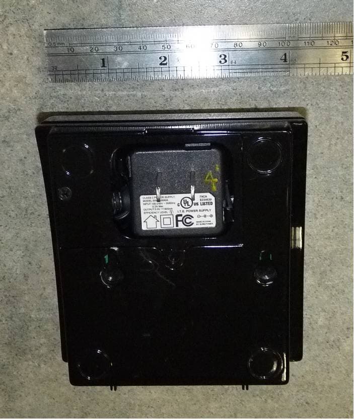
Click to zoom
Application Details
- Equipment Class
- DSS - Part 15 Spread Spectrum Transmitter
- Date of Grant
- Mar 13, 2013
- Application Purpose
- Original Equipment
- Date of Application
- Mar 13, 2013
- Equipment Note
- REMOTE SPEAKER MICROPHONE SYSTEM
- Frequency Range
- 2401.05600000 - 2482.27200000
- Company
- Nice North America LLC
- Country
- United States
Documents & Files
Document Text
Text extracted from the exhibit documents filed with the FCC. Open a document above to read the original.
Users Manual
In Case of Emergency Press Here PERS Console Operating Modes Your PERS Console operates in three operating “modes”. Each mode sets the Console to act differently to match your lifestyle at different times of the day. In any of the three modes, the Console is always ready to report an emergency if you press the HELP button or activate one of your portable emergency sensors. Home Mode Home Mode is for when you are at home during the day. In Home Mode, the Console knows if your emergency sensors are present and ready to use. If a sensor does not regularly report to the Console, a trouble report can be sent to your monitoring service. Away Mode Away Mode is for when you are going to be away from home. In Away Mode, the Console knows that your portable emergency sensors might be away from the Console and will abstain from reporting any sensors that are missing. Console announcements and reminder messages are also suppressed in Away Mode. Night Mode Night Mode is for nighttime when you are sleeping or do not wish to be disturbed. In Night Mode, Console operates the same as in Home Mode except that announcements and reminder messages are suppressed. In Case of Emergency If you need assistance, place a call to the monitoring service by pressing the HELP button on the Console or by activating one of your portable emergency sensors. Remember, the portable emergency sensors send radio signals to the Console, and there is a limit to the maximum distance from the Console that the portable emergency sensors can be used. Do not press Cancel before talking to the monitoring service dispatcher or your emergency call may be canceled. The Console will announce “Emergency call being placed”. When your monitoring service receives the call, they will verify the nature of your emergency and dispatch help for you. If the Console’s 2-way communications are active, the Console will announce “Emergency reported, please stand by”. The monitoring service can talk and listen to you to through the Console. PERS Console Special Features In addition to the three operating modes, your PERS Console contains several special features that can be turned on or off by your monitoring service. Activity Timer When the activity timer is on, you will need to press the Home button or activate a special sensor every day to prevent an automatic alarm from triggering. Your monitoring service can set one or two time periods that will be available to you to reset the activity timer. The activity timer is always off in Away Mode or Night Mode. Activity time period #1: ___:___ AM or PM to ___:___ AM or PM Activity time period #2: ___:___ AM or PM to ___:___ AM or PM Smoke & Carbon Monoxide Detection For increased protection, wireless smoke and carbon monoxide detectors can be setup as sensors with your PERS Console. In case of a dangerous fi re or gas event, the sensor will sound its alarm and the Console’s alarm, which can be reported to the monitoring service. Reminder Messages Five pre-recorded reminder messages can be announced by the Console at set dates and times. The messages can inform you when it’s time for an appointment, your medicine, a ride, or to test your PERS system. One special message can also be set up as an alarm clock. Press Cancel to silence a reminder message. Temperature Alarms The Console contains a sensor that constantly monitors the room temperature. The system can report if the room temperature goes higher or lower that limits preset by your monitoring service. High temperature limit:_____ Low temperature limit:_____ Speakerphone Mode The Console can be set up to work as a hands-free speakerphone for incoming calls. Pressing the HELP button or activating an emergency sensor while the telephone is ringing will answer the call. Pressing HELP or activating an emergency sensor during the call will disconnect the caller. Remote Call-in Speakerphone Mode The Console can be set up to answer the phone and start the speakerphone automatically after the caller enters a 4-digit password. The caller can talk and listen to you through the Console’s speaker and microphone. PERS Console Alarm Priorities Each type of alarm is assigned a priority. Higher priority alarms override lower priority alarms. Smoke alarms (on/off horn sound) have the highest priority, followed by carbon monoxide alarms (on/ off buzz sound), emergency alarms (3 beeps sound), then other types of maintenance and reminder reports (various sounds). PERS Console Wristband SensorSmoke SensorPendant SensorCarbon Monoxide Sensor HOME BUTTON / INDICATOR • Resets the activity timer • Press to announce the current time • Press for 5 seconds to switch between Home Mode and Away Mode • Lights green in Home Mode • Blinks green when the activity timer is running • Flashes green when less than 15 minutes remain on the activity timer ANTENNA • Receives wireless signals from emergency sensors • Sensors can be up to 1000 feet from the Console (the maximum distance will vary per installation) MICROPHONE • Listens for your voice • Used for 2-way communications with monitoring service • Used during Speakerphone Mode TEMPERATURE SENSOR • Measures room temperature • Can report if the room temperature is too high or too low SPEAKER • Sounds alarms • Speaks voice announcements • Speaks reminder messages • Used for 2-way voice communications with the monitoring service • Used during Speakerphone Mode • Sounds steady warning tone if Console fails • Speaker volume adjustment on bottom of the Console (must be set so announcements can be heard from across the room) OPTION MODULE(S) • One or two option modules can be installed • Modules plug into the rear of the Console • Option for cellular telephone reporting • Option for a wireless remote speaker / microphone HELP BUTTON / INDICATOR • Press to trigger the emergency alarm • Press to answer an incoming call if Speakerphone Mode is enabled • Lights green during normal operation • Flashes red while sending alarm reports to the monitori…
Text truncated - open the document above for the full version.
Users Manual
RSM-WALLRSM-BASEModule Installation Instructions PRODUCT DESCRIPTIONThe Remote Speaker Microphone modules, (RSM-BASE and RSM-WALL), extend the voice communication range of the PERS-4200 Console. Both of these units are equipment options designed to enhance the effectiveness of the PERS-4200 system in an emergency situation.The function of these modules establish a two-way voice link between a user and a responding central station. They allow a detailed verbal communication to the responder. The user can discuss the exact nature of the emergency so that appropriate assistance can be dispatched.The RSM-BASE module is plugged into the PERS-4200 Console. It installs into the PERS via a Linear Expansion Module Interface (LEMI) connector. Power command/control and two-way voice signals are passed through this connector. The RSM-BASE (AAE00454) and RSM-WALL (AAE00452) modules communicate wirelessly.RSM-WALL modules can be placed in key activity locations in the users home. One RSM-BASE module can support a maximum of four RSM-WALL modules. The RSM-WALL modules are either plugged into a standard electrical outlet or can be wall/ table mounted using a wall transformer with a 5’ retractable power cord. The RSM-WALL module(s) must be paired with the PERS-4200/ RSM-BASE module. Pairing instructions are included and must be performed before use. C PRODUCT DESCRIPTION RSM-BASE /PERS 4200 INSTALLPlug RSM-BASE module into Linear Expansion Module Interface (LEMI) connector on the back of the PERS-4200 console. BASIC WALL MODULE INSTALLPlug the RSM-WALL module into the lower outlet of a standard wall receptacle. The RSM-WALL module and the RSM-BASEmodule are now set up for receiving voice communication through the PERS-4200 Console. The units are ready for pairing. WALL TRANSFORMER ACCESSThe RSM-WALL module has a remote transformer that can be removed from the back of the unit to allow for unit to be wall mounted or used on a tabletop. Remove the screw fastener holding the wire access cover. WALL TRANSFORMER RELEASEUsing a screwdriver, pry spring tab while rocking the transformer block in the opposite direction. This will allow the transformer to be released from the RSM-WALL module. WALL MODULE LOCATIONSUnravel wall transformer power cord. Mount RSM-WALL module to a wall using hardware (provided), or, place RSM-WALL module on a tabletop surface near a wall outlet. PAIRING RESET/VOLUME CONTROLSThe volume and pairing reset controls are located on the bottom of the RSM-WALL module. The RSM-WALL module volume is factory set but may be adjusted if necessary. PAIRING WALL MODULE TO BASE MODULETo pair the RSM-WALL module, be sure that PERS 4200 Console is powered up and that the RSM-BASE module is plugged into the back of console. With a small pen, press and hold the reset button in for 5 seconds on both modules. The indicator on the RSM-BASE module will change from steady red (unpaired) to steady green when the pairing is successful. UN-PAIRING WALL MODULE/BASE MODULEIf it is necessary to UN-PAIR the RSM-WALL module from the RSM-BASE module (and PERS_4200 console), do the following:On the RSM-WALL module, press and hold reset button for 10 seconds. The indicator fl ashes alternating between red and green to signify unlearn mode and will return to a steady RED, completing the un-pair process.If the RSM-WALL module cannot be un-paired using the above method, ALL RSM-WALL modules can be un-paired at the RSM_BASE by pressing and holding the reset button for 30 seconds. During the fi rst 10 seconds the LED will fl ash red and green. After 30 seconds the indicator will turn RED to indicate all RSM-WALL modules have been removed from memory. NOTE: You will have to re-pair those RSM-WALL modules that are not removed. An alternative to the above method - Don’t remove, just over write. The maximum is four. First one unlearned is the fi rst one overwritten. LINEAR LIMITED WARRANTYThis Linear product is warranted against defects in material and workmanship for twelve (12) months. The Warranty Expiration Date is labeled on the product. This warranty extends only to wholesale customers who buy direct from Linear or through Linear’s normal distribution channels. Linear does not warrant this product to consumers. Consumers should inquire from their selling dealer as to the nature of the dealer’s warranty, if any. There are no obligations or liabilities on the part of Linear Corporation for consequential damages arising out of or in connection with use or performance of this product or other indirect damages with respect to loss of property, revenue, or profi t, or cost of removal, installation, or reinstallation. All implied warranties, including implied warranties for merchantability and implied warranties for fi tness, are valid only until Warranty Expiration Date as labeled on the product. This Linear Corporation Warranty is in lieu of all other warranties express or implied.All products returned for warranty service require a Return Product Authorization Number (RPA#). Contact Linear Technical Service at 1-800-421-1587 for an RPA# and other important details. IMPORTANT !!! Linear radio controls provide a reliable communications link and fi ll an important need in portable wireless signaling. However, there are some limitations which must be observed.• For U.S. installations only: The radios are required to comply with FCC Rules and Regulations as Part 15 devices. As such, they have limited transmitter power and therefore limited range. • A receiver cannot respond to more than one transmitted signal at a time and may be blocked by radio signals that occur on or near their operating frequencies, regardless of code settings. • Changes or modifi cations to the device may void FCC compliance.• Infrequently used radio links should be tested regularly to protect against undetected interference or fault. • A general knowledge of radio and its vagaries should be gained prior to acting as a wholesale distributor or dealer, and thes…
Text truncated - open the document above for the full version.
Cover Letter(s)
LINEAR LLC 1950 CAMINO VIDA ROBLE, SUITE 150, CARLSBAD, CA 92008-6517 PHONE (760) 438-7000 ● (800) 421-1587 ● ENG. FAX (760) 438-7043 MAIL: P.O. BOX 9003 ● CARLSBAD, CA 92018-9003 01 February 2012 Nemko Canada Inc 303 River Road Ottawa, Ontario, Canada K1V 1H2 Attn: Director of Certification FCC ID: EF4AAE00452 Authority to Act as Agent On our behalf, I appoint Alan Laudani of Nemko USA Inc., 2210 Faraday Ave, STE 150, Carlsbad, CA, USA to act as our agent in the preparation of this application for equipment certification. I certify that submitted documents properly describe the device or system for which equipment certification is sought. I also certify that each unit manufactured, imported or marketed, as defined in Federal Communication Commission’s regulations will have affixed to it a label identical to that submitted for approval with this application. For instances where our authorized agent signs the application for certification on our behalf, I acknowledge that all responsibility for complying with the terms and conditions for certification, as specified by Nemko Canada Inc, still resides with Linear L:LC, 1950 Camino Vida Roble, Suite 150, Carlsbad, CA. 92008-6517, USA. This appointment is in effect until December 31, 2012. Sincerely, John W. Kuivinen, P.E. Regulatory Compliance Engineer
Cover Letter(s)
01 February 2013 Nemko Canada Inc 303 River Road Ottawa, Ontario, Canada K1V 1H2 Attn: Director of Certification Re: Request of Confidentiality for FCC ID#: EF4AAE00452 Pursuant to Sections 0.457(d)(I)(ii) and 0.459 of the Commission’s Rules, the Applicant hereby requests confidential treatment of information accompanying as outlined below: Schematics, Parts List, Operating Description, Block Diagrams The above materials contain trade secrets and proprietary information not customarily released to the public. The public disclosure of these matters might be harmful to the Applicant and provide unjustified benefits to its competitors. The Applicant understands that pursuant to Rule 0.457(d)(I)(ii), disclosure of this Application and all accompanying documentation will not be made before the date of the Grant for this Application. Sincerely yours, John W. Kuivinen, P.E. Senior Regulatory Compliance Engineer LINEAR LLC 1950 CAMINO VIDA ROBLE, SUITE 150, CARLSBAD, CA 92008-6517 PHONE (760) 438-7000 ● (800) 421-1587 ● ENG. FAX (760) 438-7043 MAIL: P.O. BOX 9003 ● CARLSBAD, CA 92018-9003
ID Label/Location Info
Label installed here LINEAR LLC MODEL: RSM‐WALL FCC: EF4AAE00452 IC: 1078A‐AAE00452 Made in China
RF Exposure Info
Evaluation of MPE limit at a given distance Equation from page 18 of OET Bulletin 65, Edition 97-01where: S = power density P = power input to the antennaG = power gain of the antenna in the direction of interest relative to an isotropic radiatorR = distance to the center of radiation of the antenna Maximum peak output power --Conducted 26.42 dBm 0.439 (W) Antenna gain(typical): 2.15 (dBi) Maximum antenna gain: 1.64 (numeric) Evaluation distance: 20.00 (cm) Evaluation frequency: 2401.056 (MHz) Limit from table below: 1 (mW/cm^2) Power density at Evaluation frequency: 0.143 (mW/cm^2) EUT complies FCC/LSGAC Local Official’s Guide to RFA LOCAL GOVERNMENT OFFICIAL'S GUIDE TO TRANSMITTING ANTENNA RFEMISSION SAFETY: RULES, PROCEDURES, AND PRACTICAL GUIDANCE 2 4 R PG S
Test Report
Nemko USA, Inc. 2210 Faraday Street, Suite 150 Carlsbad, CA 92008 Phone (760) 444-3500 Fax (760) 444-3505 FCC Part 15 Subpart C, 15.247 : 13/03/2013 CERTIFICATION TEST REPORT Applicant: LINEAR CORPORATION 1950 CAMINO VIDA ROBLE Carlsbad, CA 92008 Equipment Under Test (EUT): REMOTE SPEAKER MICROPHONE SYSTEM Model: RSM-WALL FCC ID: EF4AAE00452 IC: 1078A-AAE00452 In Accordance With: FCC Part 15 Subpart C, 15.247 IC RSS-210 Issue 8 December 2010 IC RSS-Gen Issue 3 December 2010 Authorized By: Nemko USA Inc. 11696 Sorrento Valley Road, Suite F San Diego, CA 92121 Tested By: Mark Phillips, EMC/RF Test Engineer Date: J ANUARY 31, 2013 Report Number: 2013 01228788-FCC Project Number: 10236006 Nex Number: 228788 Total Number of Pages: 46 Nemko USA, Inc. 2210 Faraday Street, Suite 150, Carlsbad, CA 92008 Phone (760) 444-3500 Fax (760) 444-3505 IC: 1078A-AAE00452 Report Number: 2013 01228788-FCC FCC ID: EF4AAE00452 Specification: FCC Part 15 Subpart C, 15.247 Page 2 of 46 Applicant Affirmation John Kuivinen representing Linear Corporation hereby affirms: a) That he/she has reviewed and concurs that the test shown in this report are reflective of the operational characteristics of the device for which certification is sought; b) That the device in this test report will be representative of production units; c) That all changes (in hardware and software/firmware) to the subject device will be reviewed. d) That any changes impacting the attributes, functionality or operational characteristics documented in this report will be communicated to the body responsible for approving (certifying) the subject equipment. John Kuivinen Printed name of official Signature of official 1950 Camino Vida Roble January 31, 2013 Address Date 760-438-7138 [email protected] Telephone number Email address of official NOTE—This affirmation must be signed by the responsible party before it is submitted to a regulatory body for approval. Nemko USA, Inc. 2210 Faraday Street, Suite 150, Carlsbad, CA 92008 Phone (760) 444-3500 Fax (760) 444-3505 IC: 1078A-AAE00452 Report Number: 2013 01228788-FCC FCC ID: EF4AAE00452 Specification: FCC Part 15 Subpart C, 15.247 Page 3 of 46 Section 1. Summary of Test Results 1.1 General All measurements are traceable to national standards These tests were conducted on a sample of the equipment for the purpose of demonstrating compliance with Part 15; Subpart C and RSS-210, Issue 8 December 2010. Radiated tests were conducted is accordance with ANSI C63.4-2003. Radiated emissions are made on an open area test site. A description of the test facility is on file with the FCC and IC. The assessment summary is as follows: Apparatus Assessed: RSM-WALL Specifications: FCC Part 15 Subpart C, 15.247 IC RSS-210 Issue 8 December 2010 Date Received in Laboratory: J ANUARY 14, 2013 TO JANUARY 21, 2013 Compliance Status: Complies Exclusions: None Non-compliances: None Nemko USA, Inc. 2210 Faraday Street, Suite 150, Carlsbad, CA 92008 Phone (760) 444-3500 Fax (760) 444-3505 IC: 1078A-AAE00452 Report Number: 2013 01228788-FCC FCC ID: EF4AAE00452 Specification: FCC Part 15 Subpart C, 15.247 Page 4 of 46 1.2 Report Release History: REVISION DATE COMMENTS - JANUARY 31, 2013 Prepared By: Mark Phillips - JANUARY 31, 2013 Initial Release: A. Laudani Note that the results contained in this report relate only to the items tested and were obtained in the period between the date of initial receipt of samples and the date of issue of the report. This test report has been completed in accordance with the requirements of ISO/IEC 17025. Nemko USA Inc. authorizes the applicant to reproduce this report provided it is reproduced in its entirety and for use by the company’s employees only. Any use which a third party makes of this report, or any reliance on or decisions to be made based on it, are the responsibility of such third parties. Nemko USA Inc. accepts no responsibility for damages, if any, suffered by any third party as a result of decisions made or actions based on this report. TESTED BY: Date: January 31, 2013 Mark Phillips, EMC Test Engineer APPROVED BY: Date: January 31, 2013 Alan Laudani, EMC/RF Test Engineer Nemko USA, Inc. 2210 Faraday Street, Suite 150, Carlsbad, CA 92008 Phone (760) 444-3500 Fax (760) 444-3505 IC: 1078A-AAE00452 Report Number: 2013 01228788-FCC FCC ID: EF4AAE00452 Specification: FCC Part 15 Subpart C, 15.247 Page 5 of 46 TABLE OF CONTENTS Applicant Affirmation .................................................................................................... 2 Section 1. Summary of Test Results ....................................................................... 3 1.1 General ........................................................................................................................................ 3 1.2 Report Release History: ............................................................................................................... 4 Section 2: Equipment Under Test ................................................................................ 6 2.1 Product Identification ................................................................................................................... 6 2.2 Theory of Operation ..................................................................................................................... 6 2.3 Technical Specifications of the EUT ............................................................................................ 7 Section 3: Test Conditions ........................................................................................... 8 3.1 Specifications ............................................................................................................................... 8 3.3 Test Environment ......................................................................................................................... 8 3.4 Test Equipment ...................................................................................…
Text truncated - open the document above for the full version.
Contact Information
Applicant
Josh Hansen(Engineering Manager, Regulatory & Compliance)
Technical Contact
Linear LLCJohn William Kuivinen, P.E.
7604387138
1950 Camino Vida Roble, Suite 150 · Carlsbad, California · United States
Test Firm
Nemko USA, Inc. - San Diego EMC DivisionJan Blomgren
[email protected]760-444-3500
Technical Specifications
| # | Rule Parts | Frequency Range | Power Output |
|---|---|---|---|
| 1 | 15C | 2.40 GHz - 2.48 GHz | 439.00 mW |
Other Applications from Nice North America LLC
EF400267
May 19, 2026Edge II Security Panel
Equipment Class
DSS - Part 15 Spread Spectrum TransmitterEF400266
Mar 12, 2026Wireless KVM Extender TX+RX
Equipment Class
NII - Unlicensed National Information Infrastructure TXEF400265
Mar 12, 2026Wireless KVM Extender TX+RX
Equipment Class
NII - Unlicensed National Information Infrastructure TXEF4-FGS223US
Dec 18, 2025DoubleDimmer-Control
Equipment Class
DXX - Part 15 Low Power Communication Device TransmitterEF400247
Jul 01, 2024Digital Transmitter
Equipment Class
DSS - Part 15 Spread Spectrum Transmitter