EF4ACP00878
Nice North America LLC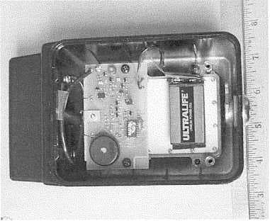
Click to zoom
Application Details
- Equipment Class
- DSC - Part 15 Security/Remote Control Transmitter
- Date of Grant
- Jul 27, 2000
- Application Purpose
- Original Equipment
- Date of Application
- Jun 07, 2000
- Frequency Range
- 318.00000000 - 318.00000000
- Company
- Nice North America LLC
- Country
- United States
Documents & Files
Document Text
Text extracted from the exhibit documents filed with the FCC. Open a document above to read the original.
ID Label/Location Info
LINEAR CORPORATION FCC ID: EF4 ACP00878 LABEL FACSIMILE FCC ID:EF4 ACP00878 Model: MDKP Remote Control Transmitter LINEAR CORPORATION This device complies with FCC Rules Part 15. Operation is subject to the following two conditions: (1) T his device may not cause harmful interference, and (2) This device must accept any interference received, including interference that may cause undesired operation.
Operational Description
LINEAR CORPORATION FCC ID: EF4 ACP00878 SPECIFICATIONS 217535 X1 MDKP, RF KEYPADSHEET 2 OF 3 1.0 DESCRIPTION 1.1The Model MDKP transmitter is a low-power communication device operating at a frequency of 318.00 MHz. The signal is a binary-coded, pulse position type A1D modulated transmission which has an information rate of approximately 167 bits per seco nd (bps). 1.2The MDTK is intended for use as a wireless alternative for AM-KP and designed to work with any 318 MHz Megacode compatible receivers such as the Linear MDR, MRDM, AKR-1. The transmitter has twelve buttons in the front. Ten buttons are used to enter a programmable security code and the "#" button is used to transmit a RF pulse modulated code sequence and the "*" has no function and is not being used. 1.3The RF transmission code is programmed by the IO numeric keys on the keypad. The user programs a unique "Personal Access Code" (PAC) that when entered will enable the RF transmitter and send a RF signal to the Megacode receiver. Each PAC code is unique and may be used to control different receivers or different channels of the same receiver. The PAC code consists of between 1 and 6 digits. Leading zeros are added to PAC codes of less than 6 digits. An all zero PAC code is disallowed, but leading zeros are permitted for a non-zero PAC code. 1.4The code is retained for 30 seco nds and if the "#" key is pressed during that time the code is present with shunt SH1 in place for regular mode. This is to allow control of the door in case of an obstruction or other emergency situation. Without shunt SH1 in place, the code is transmitted immediately and is not retained for 30 seconds if the "#" key is pressed during the time the code is present. 1.5Each press of the "#" button allows a maximum 2 second sequence of a Megacode formatted RF transmission. For factory test purposes transmit jumper WJ1 is shorted and allo ws the transmitter to transmit co ntinuo usly. After initial factory testing, WJ1 is cut and the microprocessor lockout is enabled. Pressing the "#" button first or pressing it two times in succession at any point in the cycle illuminates the keyboard Lighted Emitting Diodes (LEDs) for operation in low light levels. A 9-volt lithium battery is used to power the keypad and a 5-year life is expected witho ut the shunt SH1 in place for power saving mode. 2.0 FUNCTION 2.1A 9-volt Lithium battery (BT1) provides power to a 5-volt regulator (U1) through power gate Q1. When any butto n on the keypad is pressed microprocessor U2 is enabled. The microprocessor has a power up reset circuit R5/C11 that initializes the microprocessor and starts the keypad decoder programmed sequence. Power is maintained for 30 seconds after the last keystro ke by latch,
Test Report
LINEAR CORPORATION FCC ID: EF4 ACP00878 Radio Standard Specification Low Power Communication Devices C63.4-1992 and FCC Rules Part 15 1.0 General: 1.2 Exclusions to TV Broadcast Freq. Complies 2.0 Related Documents: Reference Documents for Application:CFR 47, FCC Rules Part 15 3.0 Test Equipment: Supply Voltage:Fresh 9 volt alkaline battery Test Equipment ListSee Section 6 Signal Detector:Peak with 15.6 dB peak to average conversion. 4.0 Certification and Test Results: Summary of Results per See Page 1 of this Report 5.0 General Technical Requirements: 5.1 Testing Methods:Peak Signal pulse position modulated A1D signal. 5.1 Reference Standard:C63.4-1992 (FCC Procedure) 5.2 Modulation:Pulse Position A1D, AM Modulation 5.3 Type of Antenna:Integral to Transmitter Case - Tuned Loop 5.4 Externa l Co ntrols:Pus h B utto ns No user serviceable parts except for replacement of battery 5.5 Accessories:NONE 5.6 TX Bandwidth:<0.010 % (See Section 8) 5.7 Equipment Labels:See Section 2 5.8 Manual Disclaimer:See attached draft copy of manual 5.9 Usage Restrictions:Digital Pulse Code Only LINEAR CORPORATION FCC ID: EF4 ACP00878 6.0 Transmitter Characteristics and Tests: 6.1 Momentary Operated Devices:Complies 6.1(a) Types of Signals:Manual Push to Transmit 6.1(a) Automatic Activation:N/A 6.1(a) Five Second Max. upon release: Complies 6.1(b) Field Strengths:Table 1 318 MHz = 6167 uV/Mtr at 3 meters. 6.1(c) Bandwidth (20 dB down)<0.010 % Complies 6.1(d) Frequency StabilityN/A per regulations +/- 0.250 MHz Maximum Error 6.1(e) Reduced Field StrengthN/A 6.2 Non-Momentary Operated Devices: N/A 6.2.1 Frequency Bands:Refer to Table 1 6.3 Restricted Bands:Complies 6.5 Pulsed Operation:Complies (15.6 dB Peak/Average) See Section 8 6.6 Wireline Conducted Emissions:N/A 7.0 ReceiversN/A 8.0 Self Certification:N/A 9.0 AC Wireline Conducted Emissions:N/A 10.0 Terminated Measurement Method:N/A 11.0 Radiated Measurement Method:See Section 8 11.1 Measuring Distance:Complies 11.2 Open Field Test Site:Complies, C63.4-1992 11.3 Equipment Test Platform:See Section 8 11.4 Measurement Method:Complies, See Section 8 12.0 DC Power Consumption Methods:N/A 13.0 Near Field Measurement for < 30 MHz:N/A 14.0 Test Report Submission:See Attached
Test Report
LINEAR CORPORATION FCC ID: EF4 ACP00878 TESTING INSTRUMENTATION AND EQUIPMENT LIST SPECTRUM ANALYZERS : H.P.HP8562A1KHz to 22GHz S/N 2913A03742Calibrated 4/00 Due 4/01 ANTENNAS : (2)Ailtech DM105A T120-200 MHzTuned Dipole S/N 93412-105 and 93412-114 Calibrated 4/00 Due:4/01 (2)Ailtech DM105A T2140-400 MHzTuned Dipole S/N 93413-113 and 93413-117 Calibrated 4/00 Due:4/01 (2)Ailtech DM105A T3400-1000 MHz Tuned Dipole S/N 93413-105 and 93414-111 Calibrated 4/00 Due 4/01 (2)AH SystemsSAS-200/5111-12.4 GHzLog Periodic S/N 118 and 124, P/Ns 2069 (1)AH SystemsSAS-200/54020-330 MHzBiconical S/N 367P/N 2052 INSTRUMENT ATION : H.P.HP8656B RF Generator100 KHz - 99O MHz S/N A4229590 Calibrated 4/00 Due 4/01 Solar Electronics Line Impedance Stabilization Network, Type 8012-50-R-24-BNCCalibrated:4/00 S/N 8379585Due:4/01 HP 8447D Broadband preamplifier, 0.1-1300 MHz S/N 2443A03660 Calibrated: 4/00 Due: 4/01 Mini-CircuitsZFL-2000 broadband preamplifier, 10-3000 MHz S/N Lin 001Calibrated: 4/00 Due: 4/01 ACCESSORIES : (2)Ailtech Rulers calibrated in MHz 4 Meter ABS Antenna Mast and Trolley Tektronix C5C Scope Camera Eighty Centimeter Tall, Motorized Wooden Turntable BNC to BNC Cables - as-required (2)25' RG-214/U Low-loss Coaxial Cable S/N- LIN001 & LIN002 Calibrated: 4/00 Due: 4/01 (2)3' RG-55/U Low-loss Coaxial Cable, calibarated as part of the preamplifiers. Automatically taken into account when used with the above itemized range preamplifiers.
Test Report
LINEAR CORPORATION FCC ID: EF4 ACP00878 MEASUREMENT OF RADIO FREQUENCY EMISSION OF CONTROL AND SECURITY ALARM DEVICES FCC RULES PART 15, C63.4-1992 TEST PROCEDURE I. INTRODUCTION As part of a continuing series of quality control tests to ensure compliance with all applicable Rules and Regulations, this enclosure details the test procedures for certain radio control devices. Testing was performed at a test site located on the property of Linear Corporation, 2055 Corte del Nogal, Carlsbad, California 92009. II. MEASUREMENT FACILITY DESCRIPTION The test facility is a specially prepared area adequately combining the desirability of an interference free location with the convenience of nearby 120 volt power outlets, thus completely eliminating the incidence of inverter hash, so often a problem with field measurements. III. DESCRIPTION OF SUPPORTING STRUCTURES For Measuring Equipment - The antenna is supported on a trolley that can be raised and lowered on a mast by means of remote control to any level between 1 meter and 4 meters above the ground. For measurements at 3 meters, an antenna height (center of dipole) of about 1 meter generally yields the greatest field strength. For measurements at 1 meter, an antenna height equal to the device under test generally yields the greatest field strength. Usually, horizontal polarization yields the greatest field strength for both 1 and 3 meter measurements. For Equipment Under Test (EUT): The equipment to be tested is supported by a wooden turntable at a height of eighty centimeters. A two axis swivel at the top of the turntable permits the unit under test to be manually oriented in the position of maximum received signal strength. The turntable can be rotated by remote control. Test Configuration - All transmitters were located eighty centimeters above ground, at a distance of three meters from the antenna. They were each oriented for maximum radiation by rotating the turntable. The antenna was then moved vertically along the mast for optimum reception in both horizontal and vertical planes. Where no emissions were found, the antenna was also moved to one meter distance to improve system sensitivity. All receivers were located eighty centimeters above ground, at a distance of three meters from the antenna. They were each oriented for maximum radiation by rotating the turntable. The antenna was then moved vertically along the mast for optimum reception in both horizontal and vertical planes. Generally, emissions were very close to the observed spectrum analyzer noise floor, making accurate measurement difficult because of the analyzer detector's characteristic of adding signal and noise. To better observe and measure emissions well above the noise floor, the antenna was moved in to one meter. This provides a theoretical 9.54 dB improvement in received field strength, but a possible shift from far field to near field antenna characteristics may introduce an unknow n error in measurement. All transmitters and receivers tested are typical of production units. A Hewlett-Packard spectrum analyzer consisting of an 8562A mainframe is used for the field strength meter. A set of Ailtech DM-105 series dipoles are used for the receiving antennas up to 1 GHz. An A. H. Systems model SAS-200/511 log periodic antenna is used from 1 to 5 GHz. Since the published antenna factor includes the small amount of balun loss, this factor is not included in the equations for correcting measured values. The cable loss is added to the raw data. For measurements up to 1 GHz, a Hewlett-Packard 8447D broadband RF preamplifier is inserted between the antenna cable and spectrum analyzer input to ensure adequate system sensitivity while measuring. LINEAR CORPORATION FCC ID: EF4 ACP00878 From 1 GHz to 3 GHz, a Mini-Circuits ZFL-2000 broadband RF preamplifier is used instead of the HP 8447D. In many cases, the antenna is moved in to a distance of 1 meter to enhance test range sensitivity after the 3 meter data is observed. A theoretical 9.54dB improvement is realized. Please see Excel data spreadsheet for details. For a particular device and frequency, the EUT to antenna distance is specified in the Report of Measurements. Correction of Measured Values - The spectrum analyzer calibration is in units of dBm absolute. Published antenna factor, measured cable loss and preamplifier gain are in units of dB. All equipment is referenced to a 50 ohm characteristic impedance; therefore, any impedance terms will factor out of any calculations. Also, balun loss is included in the antenna factor, so this term will not appear in any calculation. To obtain field strength, the reference (50 ohm system) 1 uV = 0 dBuV = -107 dBm is used. For a given frequency: antenna factor, cable loss, preamplifier gain (if used) and a 9.54 dB gain factor (3 meters to 1 meter field strength conversion) when required are factored into the spectrum analyzer reading, resulting in a field strength in units of dBm. Field strength reading (dBm) + 107 dB = dBuV, using 0 dBuV = 1 uV/meter at a specified distance as reference. All of the equipment was calibrated to NBS-traceable factory specifications prior to the date of measurement. IVMEASUREMENT PROCEDURE Transmitters 1.Set the DIP-switch rockers of the transmitter (if needed) to all ON, jam the button in the ON position, and place the transmitter on the test stand. 2.Tune the antenna (if required). 3.Tune the spectrum analyzer. 4.Adjust the antenna height and polarization for peak field strength. 5.Rotate the turntable to orient the transmitter for the highest reading. 6.Record the observed peak emission. 7.Record the screen image (if required). Spectrum Analyzer Control Settings: Tuning:As required Bandwidth100 KHz for Field Strength, Scan Width:100 KHz/div (may be different when tuning or adjusting display for photographs) Input Attenuator:10 dB Scan Time:50 mSec. sweep Reference Level:0 dBm Display Mode:Log 10 dB/division Video Filter:OFF Scan Mode:Internal Scan Trigge…
Text truncated - open the document above for the full version.
Contact Information
Applicant
Josh Hansen(Engineering Manager, Regulatory & Compliance)
Technical Contact
Linear CorporationJohn W Kuivinen
[email protected]760-438-7000
1331 H Street, NW · Carlsbad, Dist of Columbia · United States
Non-Technical Contact
Schwaninger and AssociatesRichard P Hanno
[email protected]202-347-8580
Technical Specifications
| # | Rule Parts | Frequency Range | Power Output |
|---|---|---|---|
| 1 | 15C | 318 MHz - 318 MHz | - |
Other Applications from Nice North America LLC
EF400267
May 19, 2026Edge II Security Panel
Equipment Class
DSS - Part 15 Spread Spectrum TransmitterEF400266
Mar 12, 2026Wireless KVM Extender TX+RX
Equipment Class
NII - Unlicensed National Information Infrastructure TXEF400265
Mar 12, 2026Wireless KVM Extender TX+RX
Equipment Class
NII - Unlicensed National Information Infrastructure TXEF4-FGS223US
Dec 18, 2025DoubleDimmer-Control
Equipment Class
DXX - Part 15 Low Power Communication Device TransmitterEF400247
Jul 01, 2024Digital Transmitter
Equipment Class
DSS - Part 15 Spread Spectrum Transmitter