EF4ACP00897Garage door opener
Nice North America LLC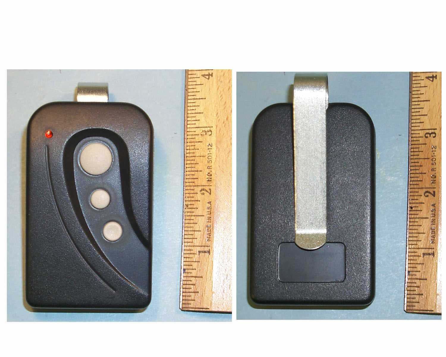
Click to zoom
Application Details
- Equipment Class
- DSC - Part 15 Security/Remote Control Transmitter
- Date of Grant
- Oct 03, 2002
- Application Purpose
- Original Equipment
- Date of Application
- Oct 03, 2002
- Equipment Note
- Garage door opener
- Frequency Range
- 318.00000000 - 318.00000000
- Company
- Nice North America LLC
- Country
- United States
Documents & Files
Document Text
Text extracted from the exhibit documents filed with the FCC. Open a document above to read the original.
Users Manual
LINEAR CORPORATION FCC ID: EF4 ACP00897 User Instruction Manual, MT-3 Transmitter
External Photos
LINEAR CORPORATION FCC ID: EF4 ACP00897 FCC ID: HERE LABEL TEXT CASE EXTERIOR VIEWS
ID Label/Location Info
LINEAR CORPORATION FCC ID: EF4 ACP00897 FCC IDENTIFICATION LABEL Model: MT-3 Remote Control Transmitter Linear Corp. requests authority to use the label as depicted, in accord with Section 2.925(e) of the Commission's Rules, follows herein. LABEL FACSIMILE Linear Corporation Model: MT-3 Frequency: 318 MHz Request for Authorization of Section 2.925(e) The device for which Linear seeks authority is small in size and does not lend itself to the placement of a label, with associated warnings and instructions, in accord with the FCC labeling requirements. For Linear to produce such a label, the type size would be too small as to be useful to purchasers of the device. Accordingly, Linear requests authority to place upon the device an identification label such as the one depicted herein identified as LABEL FACSIMILE. The additional information which is normally required to be included with the FCC Identification Number in accord with Part 15 of the Commission's Rules shall be located herein as portion of the draft manual attached hereto. Accordingly, in accord with Section 2.925(e) of the Commission's Rules and past Commission decisions, Linear hereby requests authority to label its devices in the manner described herein. The user instruction manual will have the full text of the FCC disclaimer printed in a prominent location as follows: This device complies with FCC Part 15 and Industry Canada Rules and Regulations. Operation is subject to the following two conditions: (1) This device may not cause harmful interference, and (2) This device must accept any interference received , including interference that may cause undesired operation. FCC ID: EF4 ACP00897 LINEAR CORPORATION FCC ID: EF4 ACP00897 FCC ID: HERE LABEL TEXT CASE EXTERIOR VIEWS
Internal Photos
LINEAR CORPORATION FCC ID: EF4 ACP00897 PCB Assembly, Front and Back View, MT-3 Transmitter
Operational Description
LINEAR CORPORATION FCC ID: EF4 ACP00897 SPECIFICATIONS & FUNCTIONAL DESCRIPTION MT-3 - TRANSMITTER 1.0 DESCRIPTION The MT-3 is a low-power hand held remote control device operating at a frequency of 318 MHz. The signal output is a binary-coded, pulse-position type A1D modulated transmission which has an information rate of approximately 167 bits per second (bps). It is coded by Megacode® formatted wireless data for the Linear Corporation garage door operators. Actuating any of the three push buttons illuminates a light-emitting diode (LED) and activates the transmitter. Releasing the push-button immediately terminates transmission. Transmission time is limited to 30 seconds if button is held on. 2.0 FUNCTIONAL DESCRIPTION The push-button switches, S1-3, applies power to the unit and activates L.E.D. (D1). Digital encoding is a function of microprocessor, U1. An internally generated microcontroller clock runs at approximately 4MHz and creates the coding and timing sequence. There are over 1 million possible code combinations. Transmitter coding is done during manufacture and is not user accessible. The RF oscillator Q1 functions as a tuned Colpitts oscillator / driver whose frequency control and feedback is determined by SAW resonator FR1 and R7. The frequency of oscillation is controlled by SAW resonator FR1. Q2 is the RF output amplifier. The inductive trace load E1 is configured on the circuit board as the principle-radiating element. Base bias resistors R8 & R9 in conjunction with the coupling capacitor C3 regulates the power output of the oscillator. Because of the transmitter's small size, its radiation pattern is similar to that of an elementary dipole. LINEAR CORPORATION FCC ID: EF4 ACP00897 3.0 SPECIFICATIONS Product Identification: MT-3, Three channel garage door transmitter Encoding Technique: A1D Pulse position Modulation at 167 bits/sec. Number of codes: > 1 X 10^6 RF Carrier Frequency: 318 MHz +\- 125 KHz Power Requirements: 6 VDC - 2 - 3 volt #2016 coin cell lithium batteries, 12 mA maximum current - operating, < 1 uA standby Operating Temperature Range: 0 to 50 ο C Tested –30 to +70 °C Timing: 30-second maximum transmission per activation Size: 3.75” x 2.15” x 0.90” (approx.) All specifications nominal unless specified. LINEAR CORPORATION FCC ID: EF4 ACP00897 LINEAR CORPORATION FCC ID: EF4 ACP00897 LINEAR CORPORATION FCC ID: EF4 ACP00897 LINEAR CORPORATION FCC ID: EF4 ACP00897
Schematics
LINEAR CORPORATION FCC ID: EF4 ACP00897
Test Report
LINEAR CORPORATION FCC ID: EF4 ACP00897 REPORT OF MEASUREMENTS LINEAR CORPORATION FCC ID: EF4 ACP00897 Model: MT-3 Remote Control Transmitter The enclosed documents reflect the requirements contained generally within the code of Federal Regulations, Title 47, Parts 2 and 15 as most recently published October 1, 2001 and all other applicable revisions made by the Commission since that time. The specific rule sections for which the enclosed documents demonstrate compliance or rely upon to demonstrate compliance with the Commission's application and technical standards are as follows: 15.201-15.207, 15.231, Subpart C, Intentional Radiators. Test Procedure C63.4-2001, Section 13, Measurement of Intentional Radiators was used for the testing of this device. In accord with Section 2.948 of the Commission's Rules, a Test Site submittal is on file with the commission and a Letter of Acceptance dated March 23, 2001 (File 90767) is a portion of the Commission's records. All of the information contained within this documentation is true, correct, and complete to the best of my knowledge. ____________________________ __ September 24, 2002 _ John W. Kuivinen, P.E. Date Regulatory Compliance Engineer LINEAR CORPORATION FCC ID: EF4 ACP00897 DURATION OF RF TRANSMISSIONS MT-3 REMOTE CONTROL TRANSMITTER This transmitter is manually activated. It is used only for remote control of a garage door operator. As such, it may be operated continuously by the user (FCC Rules 15.231(a)(4)). However, due to battery constraints and an accidental continuous activation causing interference to the system, the maximum manually activated transmission for a single press of a pushbutton is 30 seconds. When the push button is released the transmitter ceases transmitting immediately. FCC Rules 15.231 (a)(1) allows no longer than 5 seconds upon the release of a manually activated transmitter. Signed: John W. Kuivinen, P.E. Regulatory Compliance Engineer LINEAR CORPORATION FCC ID: EF4 ACP00897 TESTING INSTRUMENTATION AND EQUIPMENT LIST SPECTRUM ANALYZERS: H.P. HP8562A 1KHz to 22GHz S/N 2913A03742 Calibrated 12/01 Due 12/02 ANTENNAS: (2) Ailtech DM105A T1 20-200 MHz Tuned Dipole S/N 93412-105 and 93412-114 Calibrated 3/02 Due: 3/03 (2) Ailtech DM105A T2 140-400 MHz Tuned Dipole S/N 93413-113 and 93413-117 Calibrated 3/02 Due: 3/03 (2) Ailtech DM105A T3 400-1000 MHz Tuned Dipole S/N 93413-105 and 93414-111 Calibrated 3/02 Due 3/03 (2) AH Systems SAS-200/511 1-12.4 GHz Log Periodic S/N 118 and 124, P/Ns 2069 (1) AH Systems SAS-200/540 20-330 MHz Biconical S/N 367 P/N 2052 INSTRUMENTATION: H.P. HP8656B RF Generator 100 KHz - 990 MHz S/N A4229590 Calibrated 3/02 Due 3/03 Solar Electronics Line Impedance Stabilization Network, Type 8012-50-R-24-BNC Calibrated: 3/02 S/N 8379585 Due: 3/03 HP 8447D Broadband preamplifier, 0.1-1300 MHz S/N 2443A03660 Calibrated: 3/02 Due: 3/03 Mini-Circuits ZFL-2000 broadband preamplifier, 10-3000 MHz S/N Lin 001 Calibrated: 3/02 Due: 3/03 ACCESSORIES: (2) Ailtech Rulers calibrated in MHz 4 Meter ABS Antenna Mast and Trolley Tektronix C5C Scope Camera Eighty Centimeter Tall, Motorized Wooden Turntable BNC to BNC Cables - as-required (2) 25' RG-214/U Low-loss Coaxial Cable S/N- LIN001 & LIN002 Calibrated: 3/02 Due: 3/03 (2) 3' RG-55/U Low-loss Coaxial Cable, calibarated as part of the preamplifiers. Automatically taken into account when used with the above itemized range preamplifiers. LINEAR CORPORATION FCC ID: EF4 ACP00897 MEASUREMENT OF RADIO FREQUENCY EMISSION OF CONTROL AND SECURITY ALARM DEVICES FCC RULES PART 15, C63.4-2001 TEST PROCEDURE I. INTRODUCTION As part of a continuing series of quality control tests to ensure compliance with all applicable Rules and Regulations, this enclosure details the test procedures for certain radio control devices. Testing was performed at a test site located on the property of Linear Corporation, 2055 Corte del Nogal, Carlsbad, California 92009. II. MEASUREMENT FACILITY DESCRIPTION The test facility is a specially prepared area adequately combining the desirability of an interference free location with the convenience of nearby 120 volt power outlets, thus completely eliminating the incidence of inverter hash, so often a problem with field measurements. III. DESCRIPTION OF SUPPORTING STRUCTURES For Measuring Equipment - The antenna is supported on a trolley that can be raised and lowered on a mast by means of remote control to any level between 1 meter and 4 meters above the ground. For measurements at 3 meters, an antenna height (center of dipole) of about 1 meter generally yields the greatest field strength. For measurements at 1 meter, an antenna height equal to the device under test generally yields the greatest field strength. Usually, horizontal polarization yields the greatest field strength for both 1 and 3 meter measurements. For Equipment Under Test (EUT) : The equipment to be tested is supported by a wooden turntable at a height of eighty centimeters. A two axis swivel at the top of the turntable permits the unit under test to be manually oriented in the position of maximum received signal strength. The turntable can be rotated by remote control. Test Configuration - All transmitters were located eighty centimeters above ground, at a distance of three meters from the antenna. They were each oriented for maximum radiation by rotating the turntable. The antenna was then moved vertically along the mast for optimum reception in both horizontal and vertical planes. Where no emissions were found, the antenna was also moved to one meter distance to improve system sensitivity. All receivers were located eighty centimeters above ground, at a distance of three meters from the antenna. They were each oriented for maximum radiation by rotating the turntable. The antenna was then moved vertically along the mast for optimum reception in both horizontal and vertical planes. Generally, emissions were very close to the observed spectrum analyzer noise floor, making accu…
Text truncated - open the document above for the full version.
Test Report
LINEAR CORPORATION FCC ID: EF4 ACP00897 DEVICE: MT-3 Remote Control Transmitter PHOTOGRAPH: Occupied Bandwidth CONDITIONS: Transmitter Fundamental. A1D Modulation - Pulse Position Modulation. SAW Resonator Frequency Determining Element. SPECTRUM ANALYZER CONTROL SETTINGS CENTER FREQUENCY: 318 MHz INPUT ATTENUATION: -10 dB SCAN WIDTH: 5.0 KHz / Div. PREAMPLIFIER GAIN: 0 dB SCAN TIME: 0.1 Sec / Div. LOG REF. LEVEL: -10 dBm RF BANDWIDTH: 0.3 KHz ANTENNA: 6" Whip Ant. at Analyzer Input TUNED TO: N/A ANTENNA DISTANCE: 0.25 Meters ANTENNA HEIGHT: N/A SYSTEM NOISE FLOOR: N/A NOTES: Per 15.231(c), Occupied Bandwidth (20 dB down) is less than +/- 20 KHz. This is less than 0.020% of the center frequency. FCC Rules, 15.231(c) devices must be less than 0.25% of center frequency. This device therefore complies with 15.231(c). LINEAR CORPORATION FCC ID: EF4 ACP00897 DEVICE: MT-3 Remote Control Transmitter PHOTOGRAPH: Transmitter Spurious Emissions +/-25 MHz of the tuned center freq. Peak of RF signal set to zero dB reference line (top of screen). CONDITIONS: Transmitter Fundamental. A1D Modulation, SAW Resonator Frequency Determining Element. SPECTRUM ANALYZER CONTROL SETTINGS CENTER FREQUENCY: 318 MHz INPUT ATTENUATION: -10 dB SCAN WIDTH: 5.0 MHz/ Div. PREAMPLIFIER GAIN: 0 dB SCAN TIME: 1.0 Sec. / Div. LOG REF. LEVEL: -20 dBm RF BANDWIDTH: 10 KHz ANTENNA: 6" Whip Antenna on Analyzer Input TUNED TO: N/A ANTENNA DISTANCE: 0.25 Meters ANTENNA HEIGHT: N/A SYSTEM NOISE FLOOR: N/A No emissions occur outside of the of the rated center freq. except for harmonic spurious signals. LINEAR CORPORATION FCC ID: EF4 ACP00897 LINEAR CORPORATION FCC ID: EF4 ACP00897 LINEAR CORPORATION FCC ID: EF4 ACP00897 LINEAR CORPORATION FCC ID: EF4 ACP00897 LINEAR CORPORATION FCC ID: EF4 ACP00897 PRODUCT SAMPLE IN CONTINUOUS TRANSMIT. 0.8 METERS ABOVE GROUND PLANE
Contact Information
Applicant
Josh Hansen(Engineering Manager, Regulatory & Compliance)
Technical Contact
Linear CorporationJohn Kuivinen
[email protected]760-438-7000
2055 Corte Del Nogal · Carlsbad, California · United States
Non-Technical Contact
Linear CorporationJohn Kuivinen
[email protected]760-438-7000
Test Firm
Linear LLCJohn Kuivinen
Technical Specifications
| # | Rule Parts | Frequency Range | Power Output |
|---|---|---|---|
| 1 | 15.231 | 318 MHz - 318 MHz | - |
Other Applications from Nice North America LLC
EF400267
May 19, 2026Edge II Security Panel
Equipment Class
DSS - Part 15 Spread Spectrum TransmitterEF400266
Mar 12, 2026Wireless KVM Extender TX+RX
Equipment Class
NII - Unlicensed National Information Infrastructure TXEF400265
Mar 12, 2026Wireless KVM Extender TX+RX
Equipment Class
NII - Unlicensed National Information Infrastructure TXEF4-FGS223US
Dec 18, 2025DoubleDimmer-Control
Equipment Class
DXX - Part 15 Low Power Communication Device TransmitterEF400247
Jul 01, 2024Digital Transmitter
Equipment Class
DSS - Part 15 Spread Spectrum Transmitter