EF4DXS14Security Alarm Transmitter
Nice North America LLC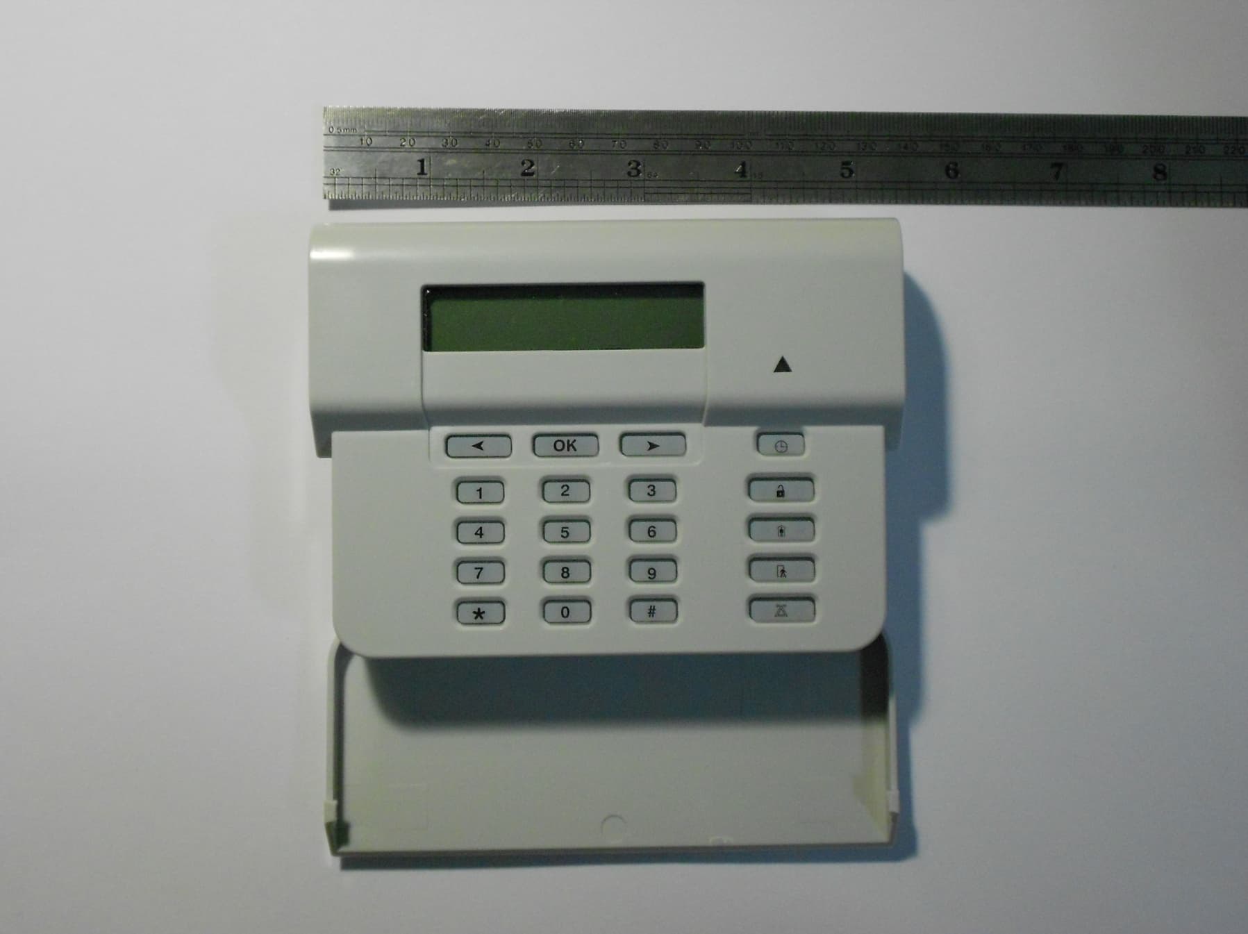
Click to zoom
Application Details
- Equipment Class
- DSC - Part 15 Security/Remote Control Transmitter
- Date of Grant
- Jun 17, 2012
- Application Purpose
- Original Equipment
- Date of Application
- Jun 17, 2012
- Equipment Note
- Security Alarm Transmitter
- Frequency Range
- 433.92000000 - 433.92000000
- Company
- Nice North America LLC
- Country
- United States
Documents & Files
Document Text
Text extracted from the exhibit documents filed with the FCC. Open a document above to read the original.
Users Manual
DXS-14 SUPERVISED REMOTE KEYPAD Operating Instructions ALARMFORCE AlarmForce Industries Inc. 675 Garyray Drive Toronto, ON M9L 1R2, Canada PRINTER’S INSTRUCTIONS: INSTR,INSTL,DXS-14 - LINEAR P/N: 233766 X3 - INK: BLACK - MATERIAL: 20 LB. MEAD BOND - SIZE: 5.500” X 8.500” - SCALE: 1-1 - FOL DING: ALBUM FOLD - BINDING: SADDLE-STITCH 2 KEYPAD OVERVIEW The LCD Supervised Remote Keypad adds remote control to Alarm Force Security System Panels. The wireless keypad transmits key presses to the panel and displays alphanumeric data received from the panel. A press of any key puts the keypad in a fully operational mode with backlit LCD and RF Transceiver active. After 15 seconds of inactivity the keypad will return to the standby mode unless tones are being generated. If tones are required, then the keypad will enter standby mode only when tone cycles have been completed. The keypad can be wall mounted and is powered by four 1.5 volt AA batteries. The batteries will operate the keypad for three years based on two minutes of operation per day. If the AA batteries become low, the keypad will send low battery reports to the panel. The keypad will continue to operate for 3 months after the fi rst low battery report. KEYPAD RESOURCES The keypad consists of 20 silicone rubber keys. The keys are backlit making it visible in low light conditions. OK 1 2 3 4 5 6 7 8 9 0 * # 3 REAL TIME CLOCK The keypad has a real time clock (RTC) that must be set during installation and after battery replacement. The RTC is required for the keypad to display time- and date-stamped events, using time offset data received from the panel. Time and date are also shown during the keypad status display when the keypad fi rst wakes up: KEYPAD READY 28/07/2011 12:45AM Depending on the country/language selected, the time and date format is: French and Spanish display: DD/MM/YYYY HH:MM (24 hour time) -- default US/English display: MM/DD/YYYY HH:MM (AM/PM) RTC time and date are set locally at the keypad from the keypad confi guration menu. A confi guration setting is also provided to manually turn on Daylight Saving Time (advances or sets back time by 1 hour). A “clock” key is provided for local keypad operation and confi guration: • Pressing the clock key once displays the keypad status and time and date on the LCD. • Pressing and holding the clock key for more than 1 second displays the time and date setting on the LCD (fl ashing digits), which can then be set using the numbers (0-9) and navigation keys ( ) on the keypad. • Pressing the clock key again provides the setting for Daylight Saving Time (DST) on/off. • Pressing OK toggles between AM-PM, DST ON-OFF • Pressing the clock key once more exits keypad set-up mode and resumes normal operation. LCD The keypad has a two line, twenty characters LCD display. The display is backlit with LEDs for low light conditions. The LCD display text is controlled by commands from the panel. The keypad will also display information on the LCD upon wake-up (“keypad status”) and in response to certain key press combinations. The LCD is capable of displaying over 200 characters and symbols. 4 Autonomous Keypad Commands and User Prompts In most operations, the keypad will only send key presses to the panel and in response the panel will update the display, LED and tone annunciations as needed to refl ect the current state of the system. When doing an initial installation or manually activated program updates the keypad will function autonomously and provide user prompts without intervention by the panel. Entering autonomous keypad command operation: When the keypad detects the long press *, it will display the following user prompt on the 2-line LCD display: SPECIAL COMMAND <-- TOGGLE CHIME --> A long press * key press message is sent to the panel at this time. At this point, the panel may respond to disallow the operation of special commands if special commands are disabled. The keypad will display the reason the command is disallowed and abort the autonomous command mode: SPECIAL COMMANDS DISABLED Alarm history The alarm history command is serviced by the ARM DISPLAY message packet. Up to 5 alarm events are sent from the panel to the keypad in a single message packet. These events are displayed one event at a time on the LCD. The user may scroll through these events by pressing the keys. Pressing OK exits the display (and autonomous command operation). Display example with 3 alarm events: 07/22/11 1:55PM ZONE 32 ALARM --> 07/20/11 11:55AM <-- ZONE 21 ALARM --> 06/17/11 12:55AM <-- ZONE 32 ALARM 5 Arming history The arming history command is serviced by the ARM DISPLAY message packet. Individual arm or disarm events are sent from the panel to the keypad in a single message packet; if arming, any bypassed zones are also included (up to 15) in the same message packet. These events are displayed one event at a time on the LCD. The user may scroll through these events and bypassed zones by pressing the keys. When viewing the last event in the list, pressing the key when displaying an event with no bypassed zones or the last bypassed zone listed will cause the keypad to send the key press to the panel, which in turn will provide a DISPLAY ARM message packet for the next event in the panel’s arming history. When viewing the fi rst event in the list, pressing the key when displaying an arm or disarm event will send the key press to the panel, which will provide a DISPLAY ARM message packet for the previous event in the panel’s arming history. Pressing OK exits the display (and autonomous command operation). Display example with 3 arming events, the fi rst one with two bypassed zones: 07/22/11 6:55AM KFOB 05 ARM AWAY --> 07/22/11 6:55AM <-- BYPASS ZONE 05 --> 07/22/11 6:55AM <-- BYPASS ZONE 08 --> 07/22/11 9:55PM <-- USER 05 ARM HOME --> 07/20/11 5:30PM <-- USER 05 DISARMED 6 Keypad Low Battery The keypad communicates a low battery condition to the panel through the low battery bit set in the KEY PRESS mess…
Text truncated - open the document above for the full version.
Block Diagram
LINEAR LLC FCC ID: EF4DXS14 IC:1078A-DXS14 LINEAR LLC FCC ID: EF4DXS14 IC:1078A-DXS14 32768 KHz Clock Timer Osc. 30 MHz Xtal
Cover Letter(s)
LINEAR LLC FCC ID: EF4DXS14 IC:1078A-DXS14 STATEMENT OF ATTESTATION Model: DXS14 Remote Control Transmitter FCC ID: EF4DXS14\ IC: 1078A-DXS14 The equipment under test is a low powered keypad remote control transceiver used with the Alarm Force series of 433.92 MHz security consoles. It is designed to send a GFSK FM modulated RF signal to the receiver when a keypad is pressed. Supervisory signals are sent approximately every 1.2 hours. Low battery monitoring functions are provided by this transmitter. The 433.92 MHz receiver will receive an acknowledgement signal at the end of each transmitted signal and display appropriate LCD display characters, as sent from the control panel. This equipment has been tested in accordance with the requirements contained in the appropriate Commission regulations. To the best of my knowledge, these tests were performed using measurement procedures consistent with industry or commission standards and demonstrate that the equipment complies with the appropriate standards. Each unit manufactured, imported or marketed, as defined in the Commission's regulations, will conform to the sample(s) tested within the variations that can be expected due to quantity production and testing on a statistical basis. I further certify that the necessary measurements were made by Linear LLC, 1950 Camino Vida Roble, Suite 150, Carlsbad, California. 92008. Certified by: __________________________ June 14, 2012 John W. Kuivinen, P.E. Date Regulatory Compliance Engineer
External Photos
LINEAR LLC FCC ID: EF4 DXS14 IC: 1078A-DXS14 LINEAR LLC FCC ID: EF4 DXS14 IC: 1078A-DXS14 CASE FRONT VIEW, KEYPAD ACCESS COVER OPEN LINEAR LLC FCC ID: EF4 DXS14 IC: 1078A-DXS14 CASE REAR VIEW WITH WALL MOUNTING BRACKET INSTALLED LINEAR LLC FCC ID: EF4 DXS14 IC: 1078A-DXS14 FCC & IC REGULATORY LABEL IN THIS AREA CASE REAR VIEW WALL MOUNTING BRACKET REMOVED LINEAR LLC FCC ID: EF4 DXS14 IC:1078A-DXS14
ID Label/Location Info
LINEAR LLC FCC ID: EF4DXS14 IC:1078A-DXS14 FCC / IC IDENTIFICATION LABEL Model: DXS-14 Remote Control Transmitter LABEL FACSIMILE FCC ID: EF4DXS14 IC:1078A-DXS14 Model: DXS-14 Frequency: 315 MHz This device complies with FCC Part 15 and IC Canada Rules and Regulations. Operation is subject to the following two conditions: (1) This device may not cause harmful interference and (2) This device is subject to any interference received, including interference that may cause undesired operation. Made in China, 454
ID Label/Location Info
LINEAR LLC FCC ID: EF4DXS14 IC: 1078A-DXS14 FCC & IC REGULATORY LABEL IN THIS AREA CASE REAR VIEW WALL MOUNTING BRACKET REMOVED
Internal Photos
LINEAR LLC FCC ID: EF4 DXS14 IC: 1078A-DXS14 PCB COMPONENT SIDE 1 LINEAR LLC FCC ID: EF4 DXS14 IC: 1078A-DXS14 433.92 MHz Transceiver Module PCB COMPONENT SIDE 2 LINEAR LLC FCC ID: EF4 DXS14 IC: 1078A-DXS14 433.92 MHz TRANSCEIVER MODULE, PCB FRONT AND BACK.
Operational Description
LINEAR LLC FCC ID: EF4DXS14 IC:1078A-DXS14 1.0 DESCRIPTION The DXS-14 is a one channel keypad transceiver operating at a frequency of 433.92 MHz. The DXS-14 is intended for use in security applications for protection of homes and dwelling units. The transmitter may be used with AlarmForce consoles. Each transmitter comes from the factory sequentially coded. Power is supplied by four 1.5 VDC AA batteries configured as two 3.0 Volt batteries in parallel. Battery life is estimated at a minimum of 3 years under typical conditions. 2.0 OPERATION The DXS14 is typically activated by pressing a key on the 20 button keypad. . A tamper switch is provided if the case top is removed. XLP Microprocessor: The XLP microprocessor (U1) controls all functions of the transceiver. The power supply is normially 3.0 VDC. As the batteries get weaker a SMPS U2 (Switch Mode Power Supply) is activated and will keep the system operating to a minimum of 1.8 VDC. Piezo annunciator U3 is drivern by oscillator U4C & U4D. The piezo signals each keystroke and will provide an emergency signal if the keypad goes into an alarm condition. RF Transceiver: Silicon Systems microprocessor/synthesizer U1 (Si10001) receives and transmits at 433.92 MHz. It has a 30 MHz reference crystal Y1 that provides the clock for an internally programmed frequency synthesizer. This IC receives, transmits and decodes the FM modulated serial data stream. Bi-directional RF switch U2 switches between transmit and receive functions for the antenna E_ANT2. In the transmit mode E_ANT2 output is filtered via lumped L/C networks LH, LO and LM. In receive mode, FL1 Is a bandpass filter that rejects spurious emissions outside of the 433.92 MHz receiver range. The transmitter is supervised. It will send a status transmission about every 1.2 hours to show the current status of the battery and contact switches. Any automatic or manually activated transmission will reset the internal status timer and the transmitter will wait another 1.2 hours to send the next status transmission. Due to battery limitations, the microprocessor IC has an internal clock that limits manually activated transmissions, even if the switch is held down, to no longer than 0.1 seconds. Only after the switch is released and then pressed again may another transmission cycle begin. LINEAR LLC FCC ID: EF4DXS14 IC:1078A-DXS14 On a brief momentary pressing of the keypad or tamper contacts, the microprocessor will power up and complete RF data message. This transmission will take approximately 100 mSec. FCC Rules 15.231 (a)(1) allows no longer than 5 seconds upon the release of a manually activated transmitter push button. The receiver will wait for an acknowledgement of the transmissions, if none is received then the signal will be sent again. Up to a maximum of 5 times. XLP Microprocessor (U1) contains a voltage comparator port that will sense a low battery if the battery is below 1.8 VDC. XLP microprocessor (U1) contains a RTC (Real Time Clock) that runs on a low power 32.768 KHz crystal oscillator. This 32.768 KHz crystal is only used tio keep track of day and date. Data communications and keyboard functions are referenced to an external 30 MHz crystal. 3.0 SPECIFICATIONS Product Identification: DXS-14 keypad transmitter. Encoding Format: GFSK FM modulated code for AlarmForce. Gaussian Frequency Shift Keyed format. Encoding Technique: Each transmitter is programmed with the sequential serial transmitter ID number. Number of Channels: One RF Carrier Frequency: 433.92 ±44 KHz Power Requirements: 3.0 VDC, 4 – 1.5 VDC AA batteries, 2 each in parallel. Visual Indicator: LED. Operating Temperature: 0° C to +70° C. Tested –20° C to 70° C. Current Consumption: 10 uA standby, 30 mA transmitting, 20 mA receiver on standby All specifications are nominal unless specified.
Schematics
LINEAR LLC FCC ID: EF4DXS14 IC:1078A-DXS14 LINEAR LLC FCC ID: EF4DXS14 IC:1078A-DXS14 LINEAR LLC FCC ID: EF4DXS14 IC:1078A-DXS14 LINEAR LLC FCC ID: EF4DXS14 IC:1078A-DXS14 LINEAR LLC FCC ID: EF4DXS14 IC:1078A-DXS14 LINEAR LLC FCC ID: EF4DXS14 IC:1078A-DXS14 LINEAR LLC FCC ID: EF4DXS14 IC:1078A-DXS14 LINEAR LLC FCC ID: EF4DXS14 IC:1078A-DXS14
Test Report
LINEAR LLC FCC ID: EF4DXS14 IC:1078A-DXS14 Application for Certification FCC ID: EF4DXS14 IC: 1078A-DXS14 DXS-14 Remote Control Transmitter Submitted by: Linear LLC 1950 Camino Vida Roble, Suite 150 Carlsbad, California 92008 760-438-7138 760-438-7043 (FAX) LINEAR LLC FCC ID: EF4DXS14 IC:1078A-DXS14 SUMMARY OF TEST RESULTS IN ACCORD WITH FCC RULES PART 15, RSS-210 ISSUE 8 DECEMBER 2010 AND C63.4-2003 Equipment Model: DXS-14 Transmitter Tested C63-4:2003 Section: FCC Rules 15.231 (a)(b) Field Strength at a distance of 3 meters: 6840 uV/Mtr (-4.1 dB below limit) @ 433.92 MHz Peak to Average Ratio: 14.9 dB - Worst Case Duty Cycle Test Conditions: Radiated (Sections 11 & 13) Transmitter: Transmitter Frequency: 433.92 MHz Nominal (Factory Tuned Only) Bandwidth (20 dB down) < 0.020% of Center Freq. Frequency Tolerance: N/A (Nominal +/- 0.045MHz) Frequency Stability: N/A (Nominal +/- 0.045MHz) Transmitter Spurious at 3 meters: 103 uV/Mtr (-21 dB below limit) (Worst Harmonic) Frequency: 868 MHz Momentary Operation (Yes/No) Yes Holdover time after manual release: 0.5 seconds (maximum) Duration of transmission after activation: 0.5 seconds on any single automatic activation Attestation: The radio apparatus identified in the application has been subject to all the applicable test conditions specified in FCC Rules Part 15 and all of the requirements of the Standard have been met. Regulatory Compliance Engineer John W. Kuivinen, P.E. ___________________________ Date: June 14, 2012 LINEAR LLC FCC ID: EF4DXS14 IC:1078A-DXS14 Radio Standard Specification Low Power Communication Devices C63.4-2003 and FCC Rules Part 15 1.0 General: 1.2, Exclusions to TV Broadcast Freq. Complies 2.0 Related Documents: Reference Documents for Application: CFR 47, FCC Rules Part 15 3.0 Test Equipment: Supply Voltage: Four fresh 1.5 VDC alkaline batteries configured as two 3 Volt batteries in parallel. Test Equipment List See Section 6 Signal Detector: Peak with 14.9 dB, peak to average conversion. 4.0 Certification and Test Results: Summary of Results per See Page 1 of this Report 5.0 General Technical Requirements: 5.1 Testing Methods: Peak Signal pulse width GFSK (Gaussian Frequency Shift Keyed) modulated FM signal. 5.1 Reference Standard: C63.4-2003 (FCC Procedure) 5.2 Modulation: Pulse Position, A1D, AM Modulation 5.3 Type of Antenna: Integral to Transmitter PCB 5.4 External Controls: 20 button keypad controls No user serviceable parts except for replacement of batteries. 5.5 Accessories: NONE 5.6 TX Bandwidth: <0.020 % (See Section 8) 5.7 Equipment Labels: See Section 2 5.8 Manual Disclaimer: See attached draft copy of manual 5.9 Usage Restrictions: Digital Pulse Code Only LINEAR LLC FCC ID: EF4DXS14 IC:1078A-DXS14 6.0 Transmitter Characteristics and Tests: 6.1 Momentary Operated Devices: Complies 6.1(a) Types of Signals: Manual Push to Transmit 6.1(a) Automatic Activation: N/A 6.1(a) Five Second Max. upon release: Complies 6.1(b) Maximum Field Strength: 433.92 MHz = 11,000 uV/mtr at 3 meters. 6.1(c) Bandwidth (20 dB down) <0.020 % Complies 6.1(d) Frequency Stability N/A per regulations +/- 0.045MHz Maximum Error 6.1(e) Reduced Field Strength N/A 6.2 Non-Momentary Operated Devices: N/A 6.2.1 Frequency Bands: Refer to Table 1 6.3 Restricted Bands: Complies 6.5 Pulsed Operation: Complies (14.9 dB Peak/Average) See Section 8 6.6 Wireline Conducted Emissions: N/A 7.0 Receivers Complies 8.0 Self Certification: N/A 9.0 AC Wireline Conducted Emissions: N/A 10.0 Terminated Measurement Method: N/A 11.0 Radiated Measurement Method: See Section 8 11.1 Measuring Distance: Complies 11.2 Open Field Test Site: Complies, C63.4-2003 11.3 Equipment Test Platform: See Section 8 11.4 Measurement Method: Complies, See Section 8 12.0 DC Power Consumption Methods: N/A 13.0 Near Field Measurement for < 30 MHz: N/A 14.0 Test Report Submission: See Attached LINEAR LLC FCC ID: EF4DXS14 IC:1078A-DXS14 LINEAR LLC FCC ID: EF4DXS14 IC:1078A-DXS14 REPORT OF MEASUREMENTS LINEAR LLC FCC ID: EF4DXS14 IC: 1078A-DXS14 Model : DXS14 Remote Keypad Transceiver The enclosed documents reflect the requirements contained generally within the code of Federal Regulations, Title 47, Parts 2 and 15 as most recently published October 1, 2011 and all other applicable revisions made by the Commission since that time. The specific rule sections for which the enclosed documents demonstrate compliance or rely upon to demonstrate compliance with the Commission's application and technical standards are as follows: 15.201-15.207, 15.231, Subpart C, Intentional Radiators. 15.35 Unintentional Radiators, Subpart B. Test Procedure C63.4-2003, Section 13, Measurement of Intentional Radiators and Test Procedure C63.4-2003, Class B, Measurement of Un-intentional radiators were used for the testing of this device.. In accord with Section 2.948 of the Commission's Rules, a Test Site submittal is on file with the commission and a Letter of Acceptance dated March 16, 2012 (File 90767) is a portion of the Commission's records. A test site submittal is on file with Industry Canada. The Industry Canada file number is 1078A-1. The file is dated August 4, 2010. All of the information contained within this documentation is true, correct, and complete to the best of my knowledge. ____________________________ June 14, 2012 John W. Kuivinen, P.E. Date Regulatory Compliance Engineer LINEAR LLC FCC ID: EF4DXS14 IC:1078A-DXS14 MEASUREMENT OF RADIO FREQUENCY EMISSION OF CONTROL AND SECURITY ALARM DEVICES FCC RULES PART 15, C63.4-2003 TEST PROCEDURE I. INTRODUCTION As part of a continuing series of quality control tests to ensure compliance with all applicable Rules and Regulations, this enclosure details the test procedures for certain radio control devices. Testing was performed at a test site located on the property of Linear LLC, 1950 Camino Vida Roble, Suite 150, Carlsbad, California 92008. II. MEASUREMENT FACILITY DESCRIPTION The test facility is a specially prepared area adequately combining …
Text truncated - open the document above for the full version.
Test Setup Photos
LINEAR LLC FCC ID: EF4 DXS14 IC: 1078A-DXS14 TEST SAMPLE ON ANTENNA RANGE LINEAR LLC FCC ID: EF4 DXS14 IC: 1078A-DXS14 EMISSIONS MEASUREMENT SET UP
Contact Information
Applicant
Josh Hansen(Engineering Manager, Regulatory & Compliance)
Technical Contact
Linear, LLCJohn W. Kuivinen, PE
[email protected]760-438-7138
1950 Camino Vida Roble · Carlsbad, California · United States
Test Firm
Linear LLCJohn Kuivinen
Technical Specifications
| # | Rule Parts | Frequency Range | Power Output |
|---|---|---|---|
| 1 | 15.231 | 433.92 MHz - 433.92 MHz | - |
Other Applications from Nice North America LLC
EF400267
May 19, 2026Edge II Security Panel
Equipment Class
DSS - Part 15 Spread Spectrum TransmitterEF400266
Mar 12, 2026Wireless KVM Extender TX+RX
Equipment Class
NII - Unlicensed National Information Infrastructure TXEF400265
Mar 12, 2026Wireless KVM Extender TX+RX
Equipment Class
NII - Unlicensed National Information Infrastructure TXEF4-FGS223US
Dec 18, 2025DoubleDimmer-Control
Equipment Class
DXX - Part 15 Low Power Communication Device TransmitterEF400247
Jul 01, 2024Digital Transmitter
Equipment Class
DSS - Part 15 Spread Spectrum Transmitter