EF4LRWRemote Control / Wrist Transmitter
Nice North America LLC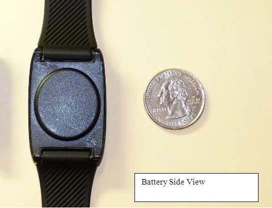
Click to zoom
Application Details
- Equipment Class
- DSC - Part 15 Security/Remote Control Transmitter
- Date of Grant
- Oct 26, 2010
- Application Purpose
- Original Equipment
- Date of Application
- Oct 25, 2010
- Equipment Note
- Remote Control / Wrist Transmitter
- Frequency Range
- 315.00000000 - 315.00000000
- Company
- Nice North America LLC
- Country
- United States
Documents & Files
Document Text
Text extracted from the exhibit documents filed with the FCC. Open a document above to read the original.
Users Manual
LINEAR LLC FCC ID:EF4LRW
Block Diagram
LINEAR LLC FCC ID:EF4LRW
Cover Letter(s)
STATEMENT OF ATTESTATION DXS-LRW The equipment under test is a low powered an emergency signaling transmitter for may be provided by this transmitter. The PCB assembly is the same as is used with the EF4LRP transmitter. Due to marking requirements from ET alternate construction. Internally these two products are identical. This equipment has been tested in accordance with the requirements contained in the appropriate Commission regulations. To the best of my performed using measurement procedures consistent with industry or commission standards and demonstrate that the equipment complies with the appropriate standards. Each unit manufactured, imported or marketed, as defined in th regulations, will conform to the sample(s) tested within the variations that can be expected due to quantity production and testing on a statistical basis. I further certify that the necessary measurements Camino Vida Roble, Suite 150 Certified by: ________________ __________ John W. Kuivinen, P.E. Regulatory Compliance Engineer LINEAR LLC FCC ID:EF4LRW STATEMENT OF ATTESTATION LRW - Remote Control Transmitter FCCID:EF4LRW The equipment under test is a low powered portable transmitter that is typically transmitter for security systems. Optional supervisory signals provided by this transmitter. The PCB assembly is the same as is used with the EF4LRP transmitter. Due to marking requirements from ETL, we must change the FCC ID number to add this alternate construction. Internally these two products are identical. This equipment has been tested in accordance with the requirements contained in the appropriate Commission regulations. To the best of my knowledge, these tests were performed using measurement procedures consistent with industry or commission standards and demonstrate that the equipment complies with the appropriate standards. Each unit manufactured, imported or marketed, as defined in the Commission's regulations, will conform to the sample(s) tested within the variations that can be expected due to quantity production and testing on a statistical basis. I further certify that the necessary measurements were made by Linear LLC no Vida Roble, Suite 150, Carlsbad, California. 92008. __________ _ October 11, 2010 Date Regulatory Compliance Engineer that is typically used as supervisory signals The PCB assembly is the same as is used with the EF4LRP transmitter. Due to L, we must change the FCC ID number to add this This equipment has been tested in accordance with the requirements contained in the knowledge, these tests were performed using measurement procedures consistent with industry or commission standards and demonstrate that the equipment complies with the appropriate standards. e Commission's regulations, will conform to the sample(s) tested within the variations that can be were made by Linear LLC, 1950 October 11, 2010 _
External Photos
[
ID Label/Location Info
ID Label clarification.txt The FCC ID: EF4LRW and IC:1078A-LRW codes are molded directly into the plastic housing. John Kuivinen, P.E. Senior Regulatory Compliance Engineer [email protected] Page 1
ID Label/Location Info
LINEAR LLC FCC ID:EF4LRW FCC IDENTIFICATION LABEL LABEL FACSIMILE FCC IDENTIFICATION LABEL FCC ID:EF4LRW IC:1078A-LRW Linear LLC requests authority to use the label as depicted, in accord with Section 2.925 of the Commission's Rules, follows herein. The device for which Linear seeks authority is small in size and does not lend itself to the placement of a label, with associated warnings and instructions, in accord with the FCC labeling requirements. For Linear to produce such a label, the type size would be too small as to be useful to purchasers of the device. Accordingly, Linear LLC requests authority to place upon the device an identification label such as the one depicted herein identified as LABEL FACSIMILE. The additional information which is normally required to be included with the FCC Identification Number in accord with Part 15 of the Commission's Rules shall be located herein as portion of the draft manual attached hereto. Accordingly, in accord with Section 2.925 of the Commission's Rules and past Commission decisions, Linear hereby requests authority to label its devices in the manner described herein. The user instruction manual will have the full text of the FCC disclaimer printed in a prominent location at the end of the instruction sheet. This device complies with FCC Part 15 and Industry Canada Rules and Regulations. Operation is subject to the following two conditions: (1) This device may not cause harmful interference, and (2) This device must accept any interference received , including interference that may cause undesired operation. LINEAR LLC Summary of Test Results in accord with FCC Rules Part 15 and C63.4-2003
Internal Photos
LINEAR LLC FCC ID:EF4LRW
Operational Description
LINEAR LLC FCC ID:EF4LRW FUNCTIONAL DESCRIPTION 1.0 DESCRIPTION The DXS-LRW is a one channel portable emergency signaling transmitter operating as a low power communication device. The center frequency is crystal stabilized at 315.00 MHz. The data output is Linear DX Code formatted. The DXS-LRW and the DX Code format are designed for use with Linear DX format 315 MHz receivers and consoles. Typical receivers that could be used with this transmitter are the DXR-701, DXS-702, DXSR-1504/8, DVS-1200/2400, Dual 824 and PERS-3600. Each DXS-LRW is programmed with a DX format factory ID code. The DX format code gives over 1 million possible transmitter IDs. One lithium coin cell batteries, type 2032 is included. The battery should last about 4 years under normal use. If the transmit push button is pressed four times during a time of 4 seconds, the DXS- LRW will go into a supervisory mode. It will thereafter send status transmissions every 2.0 hours. This supervisory signal will continue until the transmitter’s battery is exhausted. 2.0 FUNCTION When the push button is depressed, U1-4 becomes low and activates U1's program. The program provides a latch signal to keep the microprocessor alive until a minimum of 8 words (800 milli second duration) are transmitted. After the 8 words are transmitted and if the switch is now open, the processor turns off. If the button is held down for more than 30 seconds, the transmitter's output is disabled. When U1 wakes up, it outputs signals to turn on the oscillator IC U3 and to provide DX coded data. The frequency of oscillator U3 is stabilized at 315 MHz by a divide by 32 crystal time base, Y1. Data output at U1-6 modulates U3 which transmits the pulse- modulated carrier via the antenna. The battery voltage is supervised by voltage detector U2. If the nominal 3.0 Volt battery Voltage drops below 2.7 Volts the transmissions will include a low battery signal. 3.0 SPECIFICATIONS Product Identification: DXS-LRW transmitter (SST00123). Encoding Format: Linear DX Code. Encoding Technique: Transmitters are factory coded with a sequential transmitter ID number. LINEAR LLC FCC ID:EF4LRW Number of Channels: One Timing: Transmission stops after 30 seconds when button is held on. When momentarily activated the transmitter sends a minimum of 8 data words (800 milli seconds transmission). RF Carrier Frequency: 315.00 MHz ± 20 KHz. Power Requirements: One 2032 3 volt battery. Visual Indicator: Dual color display, green / red LEDs Green Steady – Battery OK Red Steady – Low Battery Green or red blinking (at end of a transmission – Tx is in supervisory mode . Operating Temperature: 0° C to +70° C. Tested –30° C to 70° C. Size: 1.2" x 2.0" x 0.3” Current Consumption: 10 mA (average) transmitting. <5 uA Standby. All specifications are nominal unless otherwise noted.
Schematics
LINEAR LLC FCC ID:EF4LRW LINEAR LLC FCC ID:EF4LRW LINEAR LLC FCC ID:EF4LRW
Test Report
REPORT OF MEASUREMENTS LINEAR LLC FCC ID:EF4LRW Model: DXS-LRW Remote Control The enclosed documents reflect the Federal Regulations, Title 47, Parts 2 and 15 as most re 2010 and all other applicable revisions made by the Commission since that time. The specific rule sections for which rely upon to demonstrate compliance with the Commission's application and technical standards are as follows: 15.201-15.207, 15.231, Subpart C, Intentional Radiators. Test Procedure C63.4-2003, Section 13 used for the testing of this device. In accord with Section 2.948 of the Commission's Rules, a Test Site submittal is on file with the commission and a Letter portion of the Commission's records. A test site submittal is on file with Industry Canada. The Industry Canada file number is 1078A-1. The file is dated August 4, 2010. All of the information contained within this documentation is t to the best of my knowledge. _______ ___________________ John W. Kuivinen, P.E. Regulatory Compliance Engineer LINEAR LLC FCC ID:EF4LRW REPORT OF MEASUREMENTS Remote Control Transmitter The enclosed documents reflect the requirements contained generally within the code of Federal Regulations, Title 47, Parts 2 and 15 as most recently published October 1, and all other applicable revisions made by the Commission since that time. The specific rule sections for which the enclosed documents demonstrate compliance or rely upon to demonstrate compliance with the Commission's application and technical 15.207, 15.231, Subpart C, Intentional Radiators. , Section 13, Measurement of Intentional Radiators was used for the testing of this device. In accord with Section 2.948 of the Commission's Rules, a Test Site submittal is on file with the commission and a Letter of Acceptance dated March 31, 2009 (File 90767) is a portion of the Commission's records. A test site submittal is on file with Industry Canada. The Industry Canada file number is 1. The file is dated August 4, 2010. All of the information contained within this documentation is true, correct, and complete ___________________ __ October 11, 2010 _ Date Regulatory Compliance Engineer requirements contained generally within the code of cently published October 1, and all other applicable revisions made by the Commission since that time. the enclosed documents demonstrate compliance or rely upon to demonstrate compliance with the Commission's application and technical , Measurement of Intentional Radiators was In accord with Section 2.948 of the Commission's Rules, a Test Site submittal is on file (File 90767) is a A test site submittal is on file with Industry Canada. The Industry Canada file number is rue, correct, and complete DURATION OF RF TRANS REMOTE CONTROL This transmitter is manually activated. security system. As such, it may be operated continuously by the user (FCC Rules 15.231(a)(4)). However, due to battery constraints and an accidental continuous activation causing interference to the system, the maximum manually activated transmission for a single press of a pushbutton is 3 When a push button is quickly transmitting only after a minimum of 8 800 milli-seconds minimum transmission allows no longer than 5 seconds upon the release of a manually activated transmitter. Signed: John W. Kuivinen, P.E. Regulatory Compliance Engineer LINEAR LLC FCC ID:EF4LRW DURATION OF RF TRANSMISSIONS DXS-LRW REMOTE CONTROL TRANSMITTER This transmitter is manually activated. Typically, it is used for remote control . As such, it may be operated continuously by the user (FCC Rules 15.231(a)(4)). However, due to battery constraints and an accidental continuous activation causing interference to the system, the maximum manually activated ingle press of a pushbutton is 30 seconds. quickly pressed but then released, the transmitter mum of 8 data words (8 words X 100 milli-second minimum transmission) have been sent. FCC Rules 15.231 (a)(1) allows no longer than 5 seconds upon the release of a manually activated transmitter. Regulatory Compliance Engineer remote control of a . As such, it may be operated continuously by the user (FCC Rules 15.231(a)(4)). However, due to battery constraints and an accidental continuous activation causing interference to the system, the maximum manually activated the transmitter will cease second/word = FCC Rules 15.231 (a)(1) allows no longer than 5 seconds upon the release of a manually activated transmitter. LINEAR LLC FCC ID:EF4LRW TESTING INSTRUMENTATION AND EQUIPMENT LIST SPECTRUM ANALYZERS: H.P. HP8594EM 9 KHz to 2.9 GHz S/N 3649A00246 Calibrated 01/22/2010 Due 01/22/2011 H.P. HP8562A 1 KHz to 22GHz S/N 2913A03742 Calibrated 07/10 Due 01/11 (Required for emissions > 2.9 GHz) ANTENNAS: (2) Ailtech DM105A T1 20-200 MHz Tuned Dipole S/N 93412-105 and 93412-114 Calibrated 7/10 Due: 7/11 (2) Ailtech DM105A T2 140-400 MHz Tuned Dipole S/N 93413-113 and 93413-117 Calibrated 7/10 Due: 7/11 (2) Ailtech DM105A T3 400-1000 MHz Tuned Dipole S/N 93413-105 and 93414-111 Calibrated 7/10 Due: 7/11 (2) AH Systems SAS-200/511 1-12.4 GHz Log Periodic S/N 118 and 124, P/Ns 2069 (1) AH Systems SAS-200/540 20-330 MHz Biconical S/N 367 P/N 2052 INSTRUMENTATION: H.P. HP8656B RF Generator 100 KHz - 990 MHz S/N A4229590 Calibrated 7/10 Due 7/11 Solar Electronics Line Impedance Stabilization Network, Type 8012-50-R-24-BNC Calibrated: 7/10 S/N 8379585 Due: 7/11 HP 8447D Broadband preamplifier, 0.1-1300 MHz S/N 2443A03660 Calibrated: 7/10 Due: 7/11 Mini-Circuits ZFL-2000 broadband preamplifier, 10-3000 MHz S/N Lin 001 Calibrated: 7/10 Due: 7/11 ACCESSORIES: (2) Ailtech Rulers calibrated in MHz 4 Meter ABS Antenna Mast and Trolley Eighty Centimeter Tall, Motorized Wooden Turntable BNC to BNC Cables - as-required (2) 25' RG-214/U Low-loss Coaxial Cable S/N- LIN001 & LIN002 Calibrated: 7/10 Due: 7/11 (2) 3' RG-400E Low-loss Coaxial Cable, calibarated as part of the preamplifiers. Automatically taken into account when used with the above itemized range preamplifiers. LINEAR LLC FCC…
Text truncated - open the document above for the full version.
Test Report
in accord with Equipment Model: Transmitter Tested to C63.4-2003 Section: Field Strength at a distance of 3 meters: Peak to Average Ratio: Test Conditions: Transmitter: Transmitter Frequency: Bandwidth (20 dB down) Frequency Tolerance: Frequency Stability: Transmitter Spurious at 3 meters: (Worst Harmonic) Frequency: Momentary Operation (Yes/No) Holdover time after manual release: Duration of transmission after activati Attestation: The radio apparatus identified in the application has been subject to all the applicable test conditions specified in FCC Rules Part 15 and all of the requirements of the Standard have been met. Regulatory Compliance Engineer John W. Kuivinen, P.E. _________________ LINEAR LLC FCC ID:EF4LRW Summary of Test Results in accord with FCC Rules Part 15 and C63.4-2003 SST00123 Section: FCC Rules 15.231 of 3 meters: 3320 uV/Mtr (- 5.2 dB below limit) @ 315 20 dB - Fixed Duty Cycle Radiated (Sections 11 & 13) 315.0 MHz Nominal (Factory Tuned Only) < 0.020% of Center Freq. N/A (Nominal +/- 0.02 MHz) N/A (Nominal +/- 0.02 MHz) 130 uV/Mtr (- 13.5 dB below limit) 2835 MHz Yes time after manual release: 0.8 seconds (maximum), 8 data words any short (>120 mSec. activation) Duration of transmission after activation: 30 seconds (maximum) on any single manual activation The radio apparatus identified in the application has been subject to all the applicable test conditions specified in FCC Rules Part 15 and all of the requirements of the Standard have been met. ___________________________ Date: October 11, 2010 dB below limit) @ 315 MHz MHz Nominal (Factory Tuned Only) on on any single manual The radio apparatus identified in the application has been subject to all the applicable test conditions specified in FCC Rules Part 15 and all of the requirements of the Standard have been met. October 11, 2010 LINEAR LLC FCC ID:EF4LRW Radio Standard Specification Low Power Communication Devices C63.4-2003 and FCC Rules Part 15 1.0 General: 1.2, Exclusions to TV Broadcast Freq. Complies 2.0 Related Documents: Reference Documents for Application: CFR 47, FCC Rules Part 15 3.0 Test Equipment: Supply Voltage: One 2032 - 3 volt lithium battery Test Equipment List See Test Equipment Signal Detector: Peak with 20 dB peak to average conversion. 4.0 Certification and Test Results: Summary of Results per FCC and Industry Canada Rules and Regulations 5.0 General Technical Requirements: 5.1 Testing Methods: Peak Signal pulse position modulated A1D signal. 5.1 Reference Standard: C63.4-2003 (FCC Procedure) 5.2 Modulation: Pulse Position 10K0 A1D, AM Modulation 5.3 Type of Antenna: Integral to Transmitter Case - Tuned Loop 5.4 External Controls: One Push Button No user serviceable parts. 5.5 Accessories: NONE 5.6 TX Bandwidth: <0.020 %, See Test Measurements 5.7 Equipment Labels: See Label Faxsimilie 5.8 Manual Disclaimer: Provided in attached draft copy of manual 5.9 Usage Restrictions: Digital Pulse Code Only LINEAR LLC FCC ID:EF4LRW 6.0 Transmitter Characteristics and Tests: 6.1 Momentary Operated Devices: Complies 6.1(a) Types of Signals: Manual Push to Transmit 6.1(a) Automatic Activation: Optional 6.1(a) Five Second Max. upon release: Complies 6.1(b) Field Strengths: Per 15.231, 315 MHz = 6042 uV/Mtr maximum at 3 meters. 6.1(c) Bandwidth (20 dB down) <0.020 % Complies 6.1(d) Frequency Stability N/A per regulations +/- 0.02 MHz Crystal Controlled Oscillator 6.1(e) Reduced Field Strength N/A 6.2 Non-Momentary Operated Devices: N/A 6.2.1 Frequency Bands: Complies 6.3 Restricted Bands: Complies 6.5 Pulsed Operation: Complies (20 dB Peak/Average) See Test Measurements 6.6 Wireline Conducted Emissions: N/A 7.0 Receivers N/A 8.0 Self Certification: N/A 9.0 AC Wireline Conducted Emissions: N/A 10.0 Terminated Measurement Method: N/A 11.0 Radiated Measurement Method: See Test Equipment Report 11.1 Measuring Distance: Complies 11.2 Open Field Test Site: Complies, C63.4-2003 11.3 Equipment Test Platform: See Test Equipment List 11.4 Measurement Method: Complies, See Test Equipment Report 12.0 DC Power Consumption Methods: N/A 13.0 Near Field Measurement for < 30 MHz: N/A 14.0 Test Report Submission: See Attached Test Equipment Report
Test Setup Photos
LINEAR LLC FCC ID:EF4LRW Fundamental Emissions, 3 Meters LINEAR LLC FCC ID:EF4LRW Non-conductive test fixture, vertical or horizontal polarization. INITIAL TESTING WAS DONE USING A DXS-LRP TRANSMITTER PCB (EF4LRP). NO ELECTRICAL CHANGES TO THIS PCB WERE MADE WHEN INCORPORATING THIS ASSEMBLY INTO THE DXS-LRW TRANSMITTER. THEREFORE THE EMISSIONS WILL BE IDENTICAL SINCE THE PLASTIC CASE IS NOT MATERIAL TO THE RF EMISSIONS. LINEAR LLC FCC ID:EF4LRW Spurious Emissions, >1 GHZ, zero distance to antenna. LINEAR LLC FCC ID:EF4LRW 630 and 945 MHz, Spurious Emissions Testing.
Contact Information
Applicant
Josh Hansen(Engineering Manager, Regulatory & Compliance)
Technical Contact
Linear LLCJohn Kuivinen
[email protected]760-438-7138
1950 Camino Vida Roble, · Carlsbad, California · United States
Test Firm
Linear LLCJohn Kuivinen
Technical Specifications
| # | Rule Parts | Frequency Range | Power Output |
|---|---|---|---|
| 1 | 15.231 | 315 MHz - 315 MHz | - |
Other Applications from Nice North America LLC
EF400267
May 19, 2026Edge II Security Panel
Equipment Class
DSS - Part 15 Spread Spectrum TransmitterEF400266
Mar 12, 2026Wireless KVM Extender TX+RX
Equipment Class
NII - Unlicensed National Information Infrastructure TXEF400265
Mar 12, 2026Wireless KVM Extender TX+RX
Equipment Class
NII - Unlicensed National Information Infrastructure TXEF4-FGS223US
Dec 18, 2025DoubleDimmer-Control
Equipment Class
DXX - Part 15 Low Power Communication Device TransmitterEF400247
Jul 01, 2024Digital Transmitter
Equipment Class
DSS - Part 15 Spread Spectrum Transmitter