EF4PIR319Wireless Motion Sensor
Nice North America LLC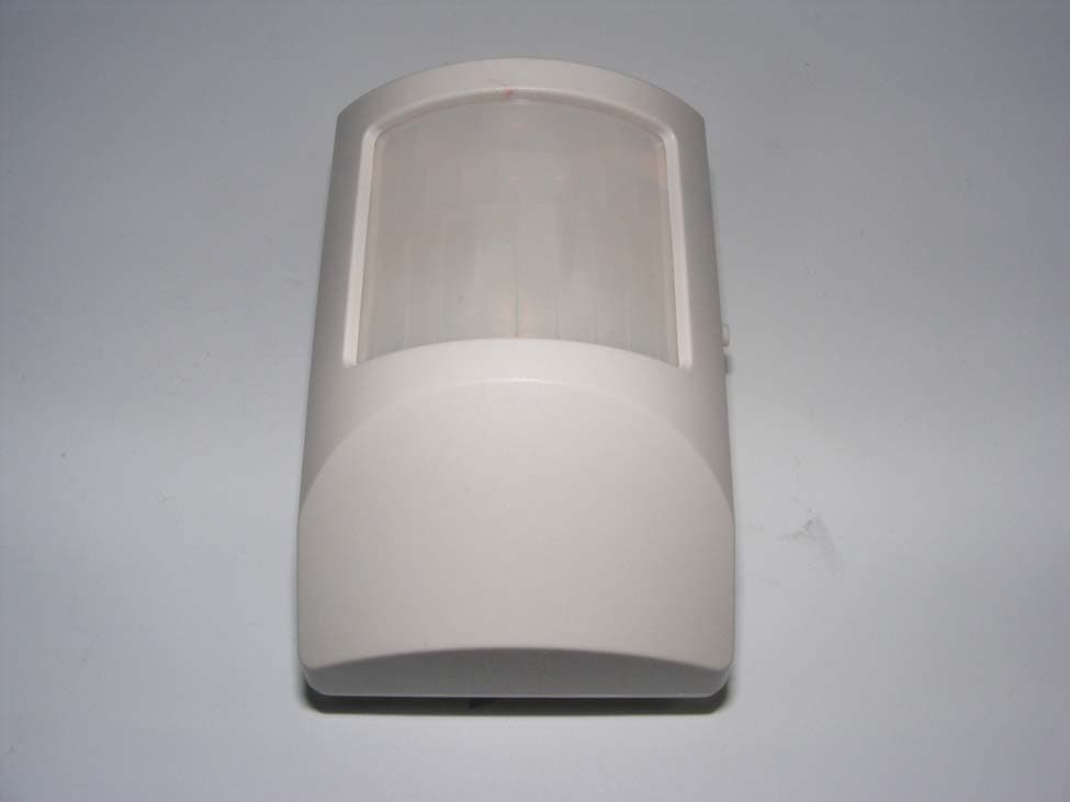
Click to zoom
Application Details
- Equipment Class
- DSR - Part 15 Remote Control/Security Device Transceiver
- Date of Grant
- Feb 18, 2013
- Application Purpose
- Original Equipment
- Date of Application
- Feb 18, 2013
- Equipment Note
- Wireless Motion Sensor
- Frequency Range
- 319.50000000 - 319.50000000
- Company
- Nice North America LLC
- Country
- United States
Documents & Files
Document Text
Text extracted from the exhibit documents filed with the FCC. Open a document above to read the original.
Users Manual
NAPPIR01SUPERVISED WIRELESSMOTION DETECTORWith Pet ImmunityInstallation Instructions PRODUCT DESCRIPTIONThe NAPPIR01 is a battery powered passive infrared motion detector with a built-in transmitter designed for use with NAPCO ® GEM and GEM-C systems. This transmitter can be used in a variety of motion detection applications. When the passive infrared sensor detects motion in its fi eld of view, the transmitter sends a digitally coded wireless signal to its companion receiver. To reduce false alarms caused by pets inside the protected area, the NAPPIR01 features pet immunity with a selectable large or small pet setting.The NAPPIR01 can send fi ve different signals: fault, restore, low battery, status, and tamper. Receivers must be programmed to the transmitter’s code before system testing and operation. Refer to the receiver’s instructions for details on programming.In a typical installation, the motion detector is mounted indoors in a corner or on a wall 7-1/2 feet high. Two mounting brackets and an adjustable PIR bracket are included. The sensor will monitor the infrared level in its detection pattern. If the level increases or decreases rapidly (as when a person moves through the area) the transmitter triggers, sending a fault signal to the receiver. A restore signal is sent when the motion stops. To conserve battery life, during normal operation, the detector can trigger the transmitter a maximum of once every three minutes. Opening the transmitter case will send a tamper signal. Being supervised, about every 65 minutes the transmitter sends a status signal to update the panel. If the battery tests low, a low battery signal is included with any transmission. The transmitter is powered from one 3-Volt CR123A lithium battery (included).For setup and testing, pressing the test button on the left side of the case places the unit in walk test mode for fi ve minute. The installer can walk in front of the unit while viewing the red test indicator through the detector’s lens to determine the detection area.The detector can be mounted directly to the wall, or by using the PIR mounting bracket assembly. The assembly connects the PIR to the corner or wall mount bracket and allows vertical and horizontal adjustment of the unit. PIR FEATURES INSTALLATION BRACKETS DETECTION PATTERN SIDE VIEW DETECTION PATTERN TOP VIEW TYPICAL INSTALLATION PIR INSTALLATION TIPS PIR INSTALLATION TIPS USA & Canada (800) 421-1587 & (800) 392-0123 (760) 438-7000 - Toll Free FAX (800) 468-1340 www.linearcorp.com PRINTER’S INSTRUCTIONS: INSTR,INSTL,NAPPIR01 - P/N:187-1132 AX1 - INK: BLACK - MATERIAL: 20 LB. MEAD BOND - SIZE: 11.000” X 8.500” - SCALE: 1-1 - SIDE 1 OF 2 WALK TE S T BUTTON PIR LEN S CA S E LOCKING BUTTTON 15K - 25K PET IMMUNITY PET S IZE JUMPER TAMPER S WITCH HIGH - LOW S EN S ITIVITY JUMPER CR12 3 A 3 -VOLT LITHIUM BATTERY CA S E ACCE SS S LOT WALL MOUNTING BRACKET CORNER MOUNTING BRACKET ADJU S TABLE PIR MOUNTING BRACKET S QUEEZE TOP AND BOTTOM OF CA S E TO OPEN 7.5 3 .75 0 0 3 6 9 12 15 1 8 21 24 27 3 0 333 6 3 940 -9 ° 7.5 3 .75 0 0 3 6 9 12 15 1 8 21 24 27 3 0 333 6 3 940 0 ° 7.5 3 .75 0 0 3 6 9 12 15 1 8 21 24 27 3 0 333 6 3 940 -1 8 ° 7.5 3 .75 0 0 3 6 9 12 15 1 8 21 24 27 3 0 333 6 3 940 +9 ° 0° IS THE PIR FACING THE OPPOSITE WALL WITH NO TILT-9° IS THE PIR TILTED DOWN ONE CLICK-18° IS THE PIR TILTED DOWN TWO CLICKS+9° IS THE PIR TILTED UP ONE CLICK ALL UNITS ARE IN FEET 0 3 6 9 12 15 1 8 21 24 27 3 0 333 6 3 942 50 ° 40 ° 3 0 ° 20 ° 10 ° 0 ° 10 ° 20 ° 3 0 ° 40 ° 50 ° DI S TANCE FROM PIR IN FEET PIR LOCATION DON'T POINT AT HEAT S OURCE S (HEATER S , ETC.), WINDOW S , OTHER MOTION DETECTOR S OR DOOR/WINDOW TRAN S MITTER S BEDROOM BATH KITCHEN FRONTROOM (FOR INDOOR U S E ONLY) MOUNT DETECTOR S O THAT INTRUDER WILL CRO SS BEAM S PIRMOTIONDETECTOR While the NAPPIR01 is a highly reliable intrusion detection device, it does not offer guaranteed protection against burglary. Any intrusion detection device is subject to compromise or failure to warn for a variety of reasons. The following issues should be considered during new installations or when troubleshooting: • If the premise has pets, make sure to follow the instructions in this manual concerning installation with pets.• This PIR has built-in protection, which keeps bugs from getting into the sensor area and causing false alarms. This does not prevent insects from crawling across the lens of the PIR, which in turn can cause the PIR to trigger an alarm. • Infrared energy can be refl ected off any glossy surface such as mirrors, windows, fl oors or counter tops with glossy fi nish, and slick fi nished concrete. Some surfaces will refl ect less than others will. For example, PIRs can see a change in infrared energy refl ected off any refl ective surface even if the heat or cold source is not within the detection pattern of the PIR. • Windows cannot only refl ect infrared energy, but they can also allow sunlight or lights from cars to pass through to the PIR. For example, a PIR can detect a quick change in infrared energy if sun light comes through a window (which may not be detected by the PIR) and shines on a hardwood fl oor (which can be detected by the PIR). If the change in infrared energy is quick enough on the fl oor, the PIR can trigger an alarm. The same applies if the PIR “covers” the window, even though the pattern of protection cannot “see” through glass. Lights from a passing car can also pass through the window at night and directly into the lens of the detector. • Heating and A/C ducts are also important to take into consideration because if they blow air onto an object within the fi elds of view, the temperature of that object could change quickly enough for the detector to see a change in infrared energy. Detectors cannot see air current, only the change in temperature of a physical object. • The PIR senses change in temperature; however, as the ambient temperature of the protected area approaches the temperature range of 95° to 120°F, th…
Text truncated - open the document above for the full version.
Cover Letter(s)
LINEAR LLC 1950 CAMINO VIDA ROBLE, SUITE 150, CARLSBAD, CA 92008-6517 PHONE (760) 438-7000 ● (800) 421-1587 ● ENG. FAX (760) 438-7043 MAIL: P.O. BOX 9003 ● CARLSBAD, CA 92018-9003 01 February 2012 Nemko Canada Inc 303 River Road Ottawa, Ontario, Canada K1V 1H2 Attn: Director of Certification FCC ID: EF4PIR319 Authority to Act as Agent On our behalf, I appoint Alan Laudani of Nemko USA Inc., 2210 Faraday Ave, STE 150, Carlsbad, CA, USA to act as our agent in the preparation of this application for equipment certification. I certify that submitted documents properly describe the device or system for which equipment certification is sought. I also certify that each unit manufactured, imported or marketed, as defined in Federal Communication Commission’s regulations will have affixed to it a label identical to that submitted for approval with this application. For instances where our authorized agent signs the application for certification on our behalf, I acknowledge that all responsibility for complying with the terms and conditions for certification, as specified by Nemko Canada Inc, still resides with Linear L:LC, 1950 Camino Vida Roble, Suite 150, Carlsbad, CA. 92008-6517, USA. This appointment is in effect until December 31, 2012. Sincerely, John W. Kuivinen, P.E. Regulatory Compliance Engineer
Cover Letter(s)
01 February 2013 Nemko Canada Inc 303 River Road Ottawa, Ontario, Canada K1V 1H2 Attn: Director of Certification Re: Request of Confidentiality for FCC ID#: EF4PIR319 Pursuant to Sections 0.457(d)(I)(ii) and 0.459 of the Commission’s Rules, the Applicant hereby requests confidential treatment of information accompanying as outlined below: Schematics, Parts List, Operating Description, Block Diagrams The above materials contain trade secrets and proprietary information not customarily released to the public. The public disclosure of these matters might be harmful to the Applicant and provide unjustified benefits to its competitors. The Applicant understands that pursuant to Rule 0.457(d)(I)(ii), disclosure of this Application and all accompanying documentation will not be made before the date of the Grant for this Application. Sincerely yours, John W. Kuivinen, P.E. Senior Regulatory Compliance Engineer LINEAR LLC 1950 CAMINO VIDA ROBLE, SUITE 150, CARLSBAD, CA 92008-6517 PHONE (760) 438-7000 ● (800) 421-1587 ● ENG. FAX (760) 438-7043 MAIL: P.O. BOX 9003 ● CARLSBAD, CA 92018-9003
ID Label/Location Info
Label: LINEAR LLC MODEL: NAPPIR01 PART #: NAPPIR01 FCC: EF4PIR319 IC: 1078A-PIR319 Made in China
Test Report
Nemko USA, Inc. 2210 Faraday Avenue, Suite 150 Carlsbad, CA 92008 Phone (760) 444-3500 Fax (760) 444-3005 FCC Part 15 Subpart C, 15.231: 29/03/2012 Certification Test Report In Accordance With: FCC Part 15 Subpart C, 15.231(e) RSS-210 Issue 8, December 2010 Applicant: Linear Corporation 1950 Camino Vida Roble Carlsbad, CA 92003 Equipment Under Test (EUT): Wireless Motion Sensor Model: NAPPIR01 FCC ID: EF4PIR319 IC: 1078A-PIR319 Tested By: Nemko USA Inc. 2210 Faraday Avenue, Suite 150 Carlsbad, CA 92008 Test Report Number: 2013 01229533 FCC Date: January 31, 2013 Project Number 10237472 NEX Number 229533 Total Number of Pages: 29 Nemko USA, Inc. 2210 Faraday Avenue, Suite 150, Carlsbad, CA 92008 Phone (760) 444-3500 Fax (760) 444-3005 FCC ID: EF4PIR319 Report Number: 2013 01229533 FCC IC: 1078A-PIR319 Specification: FCC Part 15 Subpart C, 15.231 RSS-210 Issue 8, December 2010 Page 1 of 29 Applicant Affirmation John Kuivinen representing Linear Corporation hereby affirms: a) That he/she has reviewed and concurs that the test shown in this report are reflective of the operational characteristics of the device for which certification is sought; b) That the device in this test report will be representative of production units; c) That all changes (in hardware and software/firmware) to the subject device will be reviewed. d) That any changes impacting the attributes, functionality or operational characteristics documented in this report will be communicated to the body responsible for approving (certifying) the subject equipment. John Kuivinen Printed name of official Signature of official 1950 Camino Vida Roble September 1, 2012 Address Date 760-438-7138 [email protected] Telephone number Email address of official NOTE—This affirmation must be signed by the responsible party before it is submitted to a regulatory body for approval. Nemko USA, Inc. 2210 Faraday Avenue, Suite 150, Carlsbad, CA 92008 Phone (760) 444-3500 Fax (760) 444-3005 FCC ID: EF4PIR319 Report Number: 2013 01229533 FCC IC: 1078A-PIR319 Specification: FCC Part 15 Subpart C, 15.231 RSS-210 Issue 8, December 2010 Page 2 of 29 Section 1. Summary of Test Results 1.1 General All measurements are traceable to national standards These tests were conducted on a sample of the equipment for the purpose of demonstrating compliance with Part 15; Subpart C. Radiated tests were conducted is accordance with ANSI C63.4-2003. Radiated emissions are made on an open area test site. A description of the test facility is on file with the FCC. The assessment summary is as follows: Apparatus Assessed: Wireless Motion Sensor Model: NAPPIR01 Specification: FCC Part 15 Subpart C, 15.231(e) RSS-210 Issue 8, December 2010 Date Received in Laboratory: January 24, 2013 Compliance Status: Complies Exclusions: None Non-compliances: None Nemko USA, Inc. 2210 Faraday Avenue, Suite 150, Carlsbad, CA 92008 Phone (760) 444-3500 Fax (760) 444-3005 FCC ID: EF4PIR319 Report Number: 2013 01229533 FCC IC: 1078A-PIR319 Specification: FCC Part 15 Subpart C, 15.231 RSS-210 Issue 8, December 2010 Page 3 of 29 1.2 Report Release History REVISION DATE COMMENTS - January 13, 2010 Prepared By: Mark Phillips - January 13, 2010 Initial Release: Alan Laudani Note that the results contained in this report relate only to the items tested and were obtained in the period between the date of initial receipt of samples and the date of issue of the report. This test report has been completed in accordance with the requirements of ISO/IEC 17025. Nemko USA Inc. authorizes the applicant to reproduce this report provided it is reproduced in its entirety and for use by the company’s employees only. Any use which a third party makes of this report, or any reliance on or decisions to be made based on it, are the responsibility of such third parties. Nemko USA Inc. accepts no responsibility for damages, if any, suffered by any third party as a result of decisions made or actions based on this report. Mark Phillips, RF/EMC Test Engineer Alan Laudani, RF/EMC Test Engineer Nemko USA, Inc. 2210 Faraday Avenue, Suite 150, Carlsbad, CA 92008 Phone (760) 444-3500 Fax (760) 444-3005 FCC ID: EF4PIR319 Report Number: 2013 01229533 FCC IC: 1078A-PIR319 Specification: FCC Part 15 Subpart C, 15.231 RSS-210 Issue 8, December 2010 Page 4 of 29 TABLE OF CONTENTS Applicant Affirmation ................................................................................................. 1 Section 1. Summary of Test Results .................................................................... 2 1.1 General ........................................................................................................... 2 1.2 Report Release History ................................................................................... 3 Section 2: Equipment Under Test .............................................................................. 5 2.1 Theory of Operation ........................................................................................ 5 2.2 Technical Specifications of the EUT ............................................................... 6 Section 3: Test Conditions ......................................................................................... 6 3.1 Specifications ................................................................................................. 6 3.2 Test Environment ........................................................................................... 6 3.3 Test Equipment .............................................................................................. 7 Section 4: Observations ............................................................................................. 8 4.1 Modifications Performed During Assessment ................................................. 8 4.2 Record Of Technical Judgements .................................................................. 8 4.3 EUT Parameters Affecting Compliance ...............................................…
Text truncated - open the document above for the full version.
Contact Information
Applicant
Josh Hansen(Engineering Manager, Regulatory & Compliance)
Technical Contact
Linear LLCJohn William Kuivinen, P.E.
7604387138
1950 Camino Vida Roble, Suite 150 · Carlsbad, California · United States
Test Firm
Nemko USA, Inc. - San Diego EMC DivisionJan Blomgren
[email protected]760-444-3500
Technical Specifications
| # | Rule Parts | Frequency Range | Power Output |
|---|---|---|---|
| 1 | 15.231(e) | 319.5 MHz - 319.5 MHz | - |
Other Applications from Nice North America LLC
EF400267
May 19, 2026Edge II Security Panel
Equipment Class
DSS - Part 15 Spread Spectrum TransmitterEF400266
Mar 12, 2026Wireless KVM Extender TX+RX
Equipment Class
NII - Unlicensed National Information Infrastructure TXEF400265
Mar 12, 2026Wireless KVM Extender TX+RX
Equipment Class
NII - Unlicensed National Information Infrastructure TXEF4-FGS223US
Dec 18, 2025DoubleDimmer-Control
Equipment Class
DXX - Part 15 Low Power Communication Device TransmitterEF400247
Jul 01, 2024Digital Transmitter
Equipment Class
DSS - Part 15 Spread Spectrum Transmitter