EF4RFI00001FRS Radio Transceiver
Nice North America LLC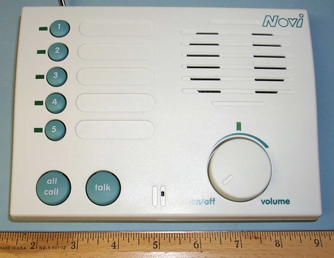
Click to zoom
Application Details
- Equipment Class
- FRB - Part 95 Family Radio Base Transmitter
- Date of Grant
- Sep 06, 2001
- Application Purpose
- Original Equipment
- Date of Application
- Sep 06, 2001
- Equipment Note
- FRS Radio Transceiver
- Frequency Range
- 467.56250000 - 467.68750000
- Company
- Nice North America LLC
- Country
- United States
Documents & Files
Document Text
Text extracted from the exhibit documents filed with the FCC. Open a document above to read the original.
Users Manual
WIRELESS INTERCOM SYSTEM 5-CHANNEL RADIO INTERCOM Installation & Operation Instructions (760) 438-7000 • FAX (760) 438-7043 USA & Canada (800) 421-1587 & (800) 392-0123 Toll Free FAX (800) 468-1340 www.linearcorp.com PRINTER’S INSTRUCTIONS: INSTRL,INSTL,RI-C - LINEAR P/N: 214601 X1 - INK: BLACK - MATERIAL: 20 LB. MEAD BOND - SIZE: 8.500” X 5.500” - SCALE: 1-1 - FOLDING: ALBUM FOLD - BINDING: SADDLE-STITCH 214601 X1 - IMAGE 1 CONSOLE DESCRIPTION Novi’s 5-channel Wireless Intercom Consoles provide a wireless audio communication link between up to five Console stations and one or two remote Wireless Doorbell Intercom units. The intercom uses digital signals to control the stations called and provide a unique “security code” that prevents other nearby Novi 5-channel intercoms from accessing the system. Either of two radio frequencies can be selected for the intercoms to further eliminate the chance of interference from adjacent systems. The Console features five station number pushbuttons for selecting the party to call. The ALL CALL button can be used to call all five stations. Pressing the TALK button calls the selected station(s), then controls the direction of the conversation. Each intercom user presses their TALK button to activate the microphone during the conversation. The Doorbell works with Console stations 4 or 5. Pressing the Doorbell’s TALK button sounds a “ding-dong” (station 5), or “dong” (station 4) at the Console, then the conversation begins by pressing the units’ talk buttons. For privacy, a MUTE switch on each Console can be set to prevent Wireless Doorbell tones and ALL CALL messages from sounding through that Console’s speaker. The Console can be placed on a table or shelf, or mounted to a wall with the screws provided. The small, antenna adjusts for Console table or wall mounting. Power for the Console is provided by a small plug-in transformer. The Doorbell attaches to a wall with the mounting plate provided. Two 9-volt alkaline batteries power the Doorbell intercom. TABLE OF CONTENTS CONSOLE DESCRIPTION..........................................................................................a CONSOLE FEATURES...............................................................................................b DOORBELL FEATURES.............................................................................................1 CONSOLE ANTENNA...............................................................................................2 PROGRAMMING THE STATIONS............................................................................3-4 WALL MOUNTING THE DOORBELL...........................................................................5 WALL MOUNTING THE CONSOLE............................................................................6 OPERATING THE DOORBELL & CONSOLE.................................................................7 OPERATING MULTIPLE CONSOLES.........................................................................8-9 TROUBLESHOOTING.............................................................................................10 CHANGING SYSTEM SETTINGS..............................................................................11 LINEAR LIMITED WARRANTY.................................................................................12 214601 X1 - IMAGE 2214601 X1 - IMAGE 3 1 CONSOLE FEATURES 1. STATION INDICATORS Indicators light when a station number button is pressed to show the station(s) that will be called. Indicators blink to show a call in progress. Indicators flash during conversation to show the busy stations. 2. STATION BUTTONS Press a button to select the intercom station(s) to be called. Pressing again de-selects the station. 3. STATION LABEL AREAS For applying labels that identify the intercom station locations. 4. ANTENNA Receives and sends the wireless intercom signals. Antenna pivots for Console horizontal and vertical mounting. 5. SPEAKER Sounds audio from the calling station. Volume is adjustable with the volume control. 6. POWER INDICATOR Lights to show that Console power is switched on. 7. VOLUME CONTROL - POWER SWITCH Switches Console power ON & OFF. Adjusts the volume of the Console’s speaker. 8. MICROPHONE High-gain microphone monitors audio from the calling station while the Console’s TALK button is pressed. 9. TALK BUTTON Press and release to call selected station(s). During conversation, press and hold when talking. 10. ALL CALL BUTTON Press to select all stations for calling. Press again to de-select all stations. 11. MUTE SWITCH When ON, the Console will not sound Doorbell Intercom chime tones or respond to All Call signals. 12. FREQUENCY SWITCH Selects frequency A or B. All intercoms used in the same system must be set to the same frequency. 3 1 2 4 5 6 7 8 9 10 11 12 214601 X1 - IMAGE 2214601 X1 - IMAGE 3 2 DOORBELL FEATURES 1. MICROPHONE High-gain microphone monitors audio while the Doorbell’s TALK button is pressed. 2. SPEAKER Sounds audio from the intercom Console. Volume is adjustable with the volume control (see Item #6). 3. POWER INDICATOR Lights to show that Doorbell power is on. Doorbell power automatically switches ON when TALK button is pressed. The power automatically switches OFF 15 seconds after the last intercom communication. 4. DOORBELL-TALK BUTTON Press to turn ON the Doorbell power and sound the chime at all of the intercom Consoles (Consoles with their MUTE switch ON will not sound the Doorbell chime). During intercom conversation, press and hold the DOORBELL-TALK button while speaking. 5. BATTERY CLIPS For connection to two 9-volt alkaline batteries. 6. VOLUME CONTROL Sets the volume level of the Doorbell’s speaker. 7. BATTERY DOOR Slides off rear case to expose the battery compartment, CHANNEL switch, and FREQUENCY switch. 8. PROGRAM BUTTON Press until two beeps sound to cause the Doorbell to enter program mode. 9. FREQUENCY SWITCH Sets the Doorbell to frequency “A” or “B”. All intercoms used in the same syst…
Text truncated - open the document above for the full version.
Block Diagram
214598 X2 L I N E A R C O R P O R A T I O N C 11 Monday, April 09, 2001 BLOCK DIAGRAM, RI-C WIDAR HE LLWIG 09APRIL01 TitleSiz e Doc ument Number Rev Date: Sheet of APPROVALS DR AWNCHECKEDENGINEER CK DATE REVISIONS DES CRIPTION REV X6 ENGINEERING PRE RELEASE APPROVAL A PRODUCTION RELEASE PER ECO # XXXX NOTES: UNLESS OTHERWISE SPECIFIED. MICR O-CO NT RO L LER CH 1 SWCH 2 SWCH 3 SWCH 4 SWCH 5 SW LOCKOUT SWPUSH- TO-TALK SWALL-CALL SWFREQ A/B SW POWER UPRESET EE MEMORYRE SETSENSE SQUEL CH T ONE FILTER RX/ TX SELECT EEPROM MICR OPHO NE MIKE ENAB LE AMPLIFIER &LIMIT ER LOW PASS FILTER DUAL PLL 4MHZ CR YST AL PLL DATA PLL CLOCK PLL ENB TEMP COMP 1ST LOOP FILTER2ND LOOP FILTER TRANSMIT VCO LP FILTER IMPEDANCE MAT CH LIMITER RF AMPLIFIER 1ST LOCAL OSCILLATOR BUFFER 1ST MIXER 2ND LOCAL OSCILLATOR MIXER ,IF, DISC RIMINATO R DA T A THRESHO LD DET EC TO R AUDIOVOLUME AUDIO ON/OFF AUDIO AMP 5V REGULATORFOR TRANSMIT 5V REGULATORF OR RECEIVE TX ENABLE RX ENAB LE RX ENABL E TX ENABLE 5V REGULATOR RF AMPLIFIER 467 MHz - TX 467 MHz - RX 417 MHz - L.O. 50 MHz - 1st IF 10.7 MHz - 2nd IF
Cover Letter(s)
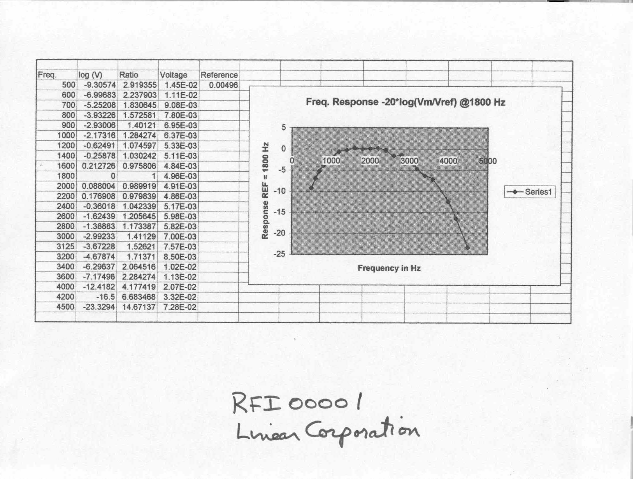
To: John K Subject: RE: Linear Corp. Part 95B radio FCC ID: EF4RFI00001 John: we have completed the review of your application, and invite your response to the following comments: 1) Form 731 emission designator: please define the necessary bandwidth to accompany the emission designator F3E. A maximum deviation of 12.5 kHz is permitted, but the necessary bandwidth should be calculated from the formulas in 2.202(b) - or, if there is no appropriate formula - on the 99% bandwidth. The value should be justified by measurement or calculation. 2) Tune-up procedure per 2.1033(c)(9): cannot find, please indicate where to look, or provide. 3) RF power per 2.1046: the measurement method is not clear. Please note that for non-detachable antennas the output power should be determined by the substitution method of ANSI/TIS/EIA-603, which is also a good guide for other mobile radio measurements. 4) Modulation characteristics per 2.1047: please provide plots of frequency characteristics and modulating limiting characteristics per the attached samples from certified devices. A table showing modulation index would be desirable. 5) Occupied bandwidth per 2.1049: How was the occupied bandwidth measured in the test report? 6) Spurious emissions at antenna terminals per 2.1051: Please provide a plot showing compliance with the emission mask, per the attached sample. 7) Frequency stability per 2.1055: Refers to a temperature limitation in the user manual, which I cannot find; please indicate where it is found. The required test range for this device is -30 to +50C, and no exceptions are generally allowed. Devices may cease operation before the extremes are met, and that is acceptable. Please comment. Thank you, Roland W. Gubisch Chief Engineer, EMC and Telecom Intertek Testing Services NA, Inc. ETL SEMKO 70 Codman Hill Road Boxborough, MA 01719 tel 978-635-8500 direct fax 978-263-7086 email [email protected] <mailto:[email protected]> -----Original Message----- From: John K [mailto:[email protected]] Sent: Friday, June 15, 2001 11:16 AM To: [email protected] Cc: Jim Repking; John Kuivinen Subject: Re: Linear Corp. Part 95B radio FCC ID: EF4RFI00001 Are things progressing OK? Do you need any further information on our RF Intercom for the FCC Certification? John Kuivinen, P.E. Regulatory Compliance Engineer Linear Corporation
External Photos
Wireless Intercom - Front Exterior View FCC ID: EF4 RFI00001Disclaimer Text at thislocation WIRELESS INTERCOM - REAR EXTERIOR VIEW
ID Label/Location Info
LABEL FACSIMILE FCC ID: EF4 RFI00001 Product ID: RFI00001 Model:FRS Base Station Radio Transceiver Linear Corporation This device complies with FCC Rules Part 15 and Family Radio System (FRS) Part 95. Operation is subject to the following two conditions: (1) This device may not cause harmful interference, and (2) This device must accept any interference received, including interference that may cause undesired operation.
Operational Description
1.0PRODUCT DESCRIPTION The RF Intercom Console (RI-C) is a five-channel intercom unit, which allows half- duplex conversation over either a 467.6875 MHz or a 467.5625 FM signal. Key features include: • 1024 random house codes (programmable) to reduce interference from units in other systems (transparent to the user). • 5 station codes (programmable). • 5 push-button switches to select the receiving station. • 5 Channel LED’s to indicate called/calling location. A fast flashing LED indicates that the corresponding station is in use. A slow flashing LED indicates that call is in progress and the unit is receiving a call. • A Press-to-Talk button. • An All Call button to select all units in the system. • A Call Lockout switch to inhibit All Call and DoorBell. • Power on LED. • Digital Calling to activate the unit only when the house and station codes match. • Tone squelch. • On/Off switch. • Internal speaker & microphone. • External antenna. • Speaker volume control. • AC wall mount transformer. 2.0HARDWARE/SOFTWARE SPECIFICATIONS 2.1MECHANICAL All electronics shall be contained in a plastic enclosure with the dimensions 7.5 x 5.5 x 1.4 inches. The body and button colors shall be gray. 2.2ELECTRICAL 2.2.1 DC CHARACTERISTICS Input Power:9VDC supplied by the AC Wall Mount Transformer Input Current:100 mA 2.2.2 AC CHARACTERISTICS System Frequency:467.6875 MHz or 467.5625 MHz Modulation Type:FM Receiver Sensitivity:-100 dBm minimum Transmitter Power Output:100 mW nominal 2.3REGULATORY AGENCIES The unit shall comply with FCC part 95 regulations. 2.4ENVIRONMENTAL Temperature:0 to +50°C (Indoor Applications) 2.5USER INTERFACE 2.5.1 SELECT CALL BUTTONS Five Select Call buttons allow selection of individual remote units. Pressing the button again will de-select the remote unit. The remote unit is also de-selected if: • The Press-to-Talk button is not pressed within 20 seconds of the call selection. • The Press-to-Talk button is not pressed within 20 seconds of the loss of incoming RF. • Correct incoming code is not detected within 20 seconds of the release of the Press- to-Talk button. 2.5.2 PRESS-TO-TALK BUTTON After selecting the remote unit using the Select Call buttons, the user may press the Press-to-Talk button to initiate RF data and voice transmission. At the press of the button, with the microphone disabled, the unit first sends out the house code, the Transmitting Station’s code, and the Receiving Station(s) code. Then the unit enables the microphone and allows the user to transmit voice over RF. When the button is released, the unit disables voice transmission and sends out an 83.3Hz tone to tell the receiving station to shut off its speaker. After a 0.25 second delay, the unit then goes into a receive mode and waits for a response. The Press-to-Talk button is also used to program the house address (refer to the programming section 3.0). 2.5.3 ALL CALL BUTTON An All Call button may be pressed to select all units with the same house address. When the Press-to-Talk button is pressed, all units will enable their speakers. If all stations have been selected, press of the All Call button will de- select all stations. The All Call button is also used to program the house address (refer to the programming section 3.0). 2.5.4 ALL CALL LOCKOUT SWITCH The All Call Lockout Switch is used to keep the speaker off during an All Call or when the doorbell is activated. 2.5.5 CHANNEL FREQUENCY SELECT SWITCH To reduce interference from non-system RF transmitters, the channel frequency may be switched between 467.6875 MHz and 467.5625 MHz, via a slide switch. 2.5.6 LED INDICATORS Five LED indicators are used to indicate called/calling locations. A blinking LED indicates that the corresponding location is in use. 2.5.7 POWER ON LED A green LED is used to indicate that the power is on. 2.5.8 VOLUME CONTROL POTENTIOMETER A potentiometer is used to control the speaker volume. 2.5.9 ON/OFF SWITCH The on/off switch is integrated with the volume control potentiometer. 2.5.10 POWER INPUT The power to the unit is supplied via a wall mount transformer. 2.6MICROCONTROLLER All programming and control functions are performed via a microcontroller on- board. 2.7RF TRANSMITTER The RF Transmitter Circuitry transmits FM data and audio over either a 467.6875 MHz or a 467.5625 MHz carrier signal. The Transmitter is disabled when its supply is shut off by the microcontroller. 2.8RF RECEIVER The RF Receiver Circuitry receives FM signals and converts them to audio and data that is usable by the microcontroller. 2.9MICROPHONE An internal microphone, which is enabled or disabled by the microcontroller, is used for audio input. 2.10 SPEAKER An internal speaker, which is enabled or disabled by the microcontroller, is used for audio output. 2.11 SQUELCH To reduce the noise that is generated on the speaker when the Press-to-Talk button is released on the transmitting unit, the transmitter sends out an 83.3Hz tone to the receiver before it shuts off RF. The receiver disables its speaker before RF goes away. If the tone is corrupted for some reason, a squelch signal that is generated by the RF Receiver is sent to the microcontroller. 2.12 CALLING STATION DATA FORMAT The transmitting station sends out a coded signal to select the appropriate receiver when the Press-to-Talk is initially pressed. The total word length is approximately 96ms. 3.0PROGRAMMING At the factory, a 10 bit, sequentially selected, house code will be programmed into the units. This code will be transparent to the customer. Also, the unit number will be “1”. Since each unit in a system may have a different house code, the house code must be re-programmed by the user. In order to do so, one unit must become the master unit and the rest of the units in the system will be slaves. The master unit must teach the house code to the units in the system. When the units are programmed, the factory code in the master will be programmed into the slaves. The programming mode shall …
Text truncated - open the document above for the full version.
Operational Description
From: Annette Beaulieu ITS/ES-La Sent: Thursday, June 07, 2001 3:30 PM To: Roland Gubisch ITS/ES-Box Subject: FW: Linear Corp. Part 95B radio FCC ID: EF4RFI00001 Annette Beaulieu Account Manager Intertek Testing Services 27611 La Paz Road, Suite C Laguna Niguel, CA 92677 Tel: 949-448-4100 Fax: 949-448-4111 [email protected] -----Original Message----- From: John K [mailto:[email protected]] Sent: Thursday, June 07, 2001 3:32 PM To: [email protected] Cc: John Kuivinen Subject: Re: Linear Corp. Part 95B radio FCC ID: EF4RFI00001 The RF final amplifier has +12 volts (regulated) at 0.017 amperes (0.20 watts) DC input. The output power at the antenna has been measured at about 100 mW (+18.9 dBm). This equates to about 50% PA efficiency for the Class C power amplifier.
Parts List/Tune Up Info
LINEAR CORPORATION SINGLE LEVEL BILL OF MATERIALS PARENT PART: RFI00001F/G RI-C ITEMPART NUMBERQTYPART DESCRIPTION 0001214594-011ASSY,MECH,RI-C 00022146011INSTRL,INSTL,RI-C 00032144921BOX,DISPLAY 00042144910.1BOX,SHIPPING 00057105391LABEL,UPC,SINGLE,BOX,RI-C 00069105390.1LABEL,BAR,SHPG CTN,RI-C 09902145930F/G,RI-C LINEAR CORPORATION SINGLE LEVEL BILL OF MATERIALS PARENT PART: RFI00001F/G RI-C ITEMPART NUMBERQTYPART DESCRIPTION 0001214596-011ASSY,PCB,RI-C 00022171081CASE,TOP,RI-C 00032171091CASE,BOTTOM,RI-C 00042171101BUTTON,CHANNEL SELECTION,RI-C 00052171111BUTTON,VOLUME,RI-C 00062171121BUTTON,FUNCTION,RI-C 00072173411PLUG,ANTENNA TIP 00082173551TUBING,ANTENNA 0,27 X 4.3 LONG 00092171151CLEVIS,PIVOT,RI-C 00102171601BRACKET,ANTENNA,RI-C 00112171141ANTENNA,ROD,0.71 X 4.4,RI-C 00122028471LABEL,WARR/DATE CODE,1 YEAR 00132146021LABEL,FCC,RI-C 00142139031RES,VAR,10K,PNLMT, S10 00152134421LED,GRN,RECTANGULAR, D1 00161008441SPKR,8 OHM 2W, LS1 00171042621.17WIRE,22,WHT,STR,BULK,UL1007 00181042940.44WIRE,22,YEL,STR,BULK,UL1007 00191041850.66WIRE,22,BRN,STR,BULK,UL1007 00201042370.25WIRE,22,RED,STR,BULK,UL1007 00211082600.25wIRE,22,BLK,STR,BULK,UL1007 00222123680.062 TUBING,HEATSHRINK,3/32"ID,BLK 00242106374WSHR,PUSH,NUT 00251034182SCR,MACH,2-56X1/4,PNH,PH LINEAR CORPORATION SINGLE LEVEL BILL OF MATERIALS PARENT PART: RFI00001F/G RI-C ITEMPART NUMBERQTYPART DESCRIPTION 00261033931SCR,CAP,SOCKET,ALLEN 00271043992WSHR,LOCK,EXTT,#2,STEEL/ZINC 00282097452NUT,HEX,#2-56,STL/ZINC 00292062844SCR,TPG,TF,4X1/2,PNH,PH,ST/ZINC 00301035791SCR,TPG,TF,4X1/4,PNH,PH,STL/ZINC 00311065970.005 GLUE,HOT MELT,3M 3762 09902145940ASSY,MECH,RI-C LINEAR CORPORATION SINGLE LEVEL BILL OF MATERIALS PARENT PART: RFI00001F/G RI-C ITEMPART NUMBERQTYPART DESCRIPTION 000221339021CAP,CER,C,50V103P,X7R,10%,0603 C1,9,12,35,41,47 49,50,58,61,63,64 67,68,75,81,83,84 88,91,96 000321339117CAP,CER,C,50V102P,X7R,10%,0603 24,40,44,46,53,73 94,99,113,201,204 00042050002CAP,TANT,C,16V105P,3216,20% 00052137812CAP,AL,CHIP,16V227P,6.3X8,20% C4,98 00062139361CAP,AL,CHIP,16V106P,3X5.5,20% C5 0007213430-0272CAP,CER,C,50V2R7P,COG,.5PF,0603 C28,62 000821341920CAP,CER,C,16V104P,X7R,10%,0603 C6,7,8,16,33,39,57 66,69,70,87,89,92 97,102,106,107,109 110,203 0009213430-1211CAP,CER,C,50V121P,COG,0603,+/-5% C90 0011213430-0334CAP,CER,C,50V3R3P,COG,.5PF,0603 C17,25,27,36 00122134182CAP,CER,C,50V1R0P,0603 C29,34 00132134443CAP,CER,C,50V1R5P,0603 C20,38,52 0014213430-0391CAP,CER,C,50V3R9P,COG,.5PF,0603 C60 001520503911CAP,TANT,C,10V475P,20%,3528 C3,10,23,55,77,82 85,95,103,105,114 00162134432CAP,CER,C,50V8R2P,0603,+/-.25PF C26,79 00172133923CAP,CER,C,50V6R8P,0603,+/-.25PF C30,31,54 00182134525CAP,CER,C,50V100P,NPO,5%,0603 C19,43,51,72,74 00192138321CAP,CER,C,50V471P,X7R,0603,10% C48 00202138352CAP,CER,C,25V473P,X7R,0603,10% C100,104 0022213430-1501CAP,CER,C,50V150P,NPO,5%,0603 C65 0023203691-0011CAP,VAR,2.5-10PF,SMD C76 0024213430-2701CAP,CER,C,50V270P,COG,0603,5% C78 0025213430-0561CAP,CER,C,50V5R6P,COG,.5PF,0603 C80 00302134426LED,GRN,RECTANGULAR D1,7,8,9,10,11 0031205011-0011DIODE,MMBD914,SWITCH,SOT-23 D2 0032205011-0032DIODE,BAV99,DUAL,SOT-23 D3,4 00332134892DIODE,MMBV3102LT1,30V,SOT23 D5,6 00402134881FILTER,CER,455KHZ,MULTI-ELEM FR1 00412060747INDCTR,10 TURN,26AWG,.038 CORE L1,4,6,7,8,9,14 0042203689-1511INDCTR,150NH,CER,SMD,1008,10% L2 00432089902INDCTR,1TURN,.141ID,#22AWG,20NH L10,11 00442138422INDCTR,VAR,14-16NH,BRN,5MM L12,15 00452131501INDCTR,.47UH,SMD,1008CS L16 00462137771INDCTR,VAR,.1-1.0UH,SHLD,5.6MM L17 00471042420WIRE,22,SLD,BARE,BULK L5 00482138651DISCRIMINATOR,455KHZ,VAR,680UH L18 00492137421XFMR,RF,455KHZ,10MM,WITH CAP T1 00512134927XSTR,MMBR911LT1,SOT-23 Q1,2,3,5,6,7,8 00541045071XSTR,NPN,MMBT3904,SOT-23 Q9 0059205144-1011RES,CHIP,1/8W,100,5%,1206 R8 0060213383-1001RES,CHIP,1/16W,10.0,0603,5% R101 0061213383-1018RES,CHIP,1/16W, 100,0603,5% R1,2,4,10,28 33,70,78 0062213383-10332RES,CHIP,1/16W, 10K,0603,5% R9,13,15,19,24,38 44,46,48,50,53,54 59,66,67,72,74,77 79,80,82,84,85,87 88,98,99,102,103 106,112,114 0063213383-1025RES,CHIP,1/16W,1.0K,0603,5% R3,65,104,107,108 0065213383-4724RES,CHIP,1/16W,4.7K,0603,5% R12,17,31,40 0066213383-1512RES,CHIP,1/16W, 150,0603,5% R11,36 0068213383-3929RES,CHIP,1/16W,3.9K,5% R16,20,22,29,37 42,43,51,63 0069213383-2733RES,CHIP,1/16W, 27K,0603,5% R21,93,96 0070213383-3322RES,CHIP,1/16W,3.3K,0603,5% R45,57 0071213383-1046RES,CHIP,1/16W,100K,0603,5% R47,49,81,95,105 0072213383-3331RES,CHIP,1/16W, 33K,0603,5% R26 0073213383-5601RES,CHIP,1/16W,56,0603,5% R55 0074213383-5614RES,CHIP,1/16W, 560,0603,5% R7,14,30,52 0075213383-1522RES,CHIP,1/16W,1.5K,0603,5% R35,41 0076213383-2232RES,CHIP,1/16W, 22K,0603,5% R39,100 0078213383-1211RES,CHIP,1/16W, 120,0603,5% R97 0079213383-4715RES,CHIP,1/16W, 470,0603,5% R62,69,73,76,83 0080213383-4701RES,CHIP,1/16W,47.0,0603,5% R64 0081213383-8221RES,CHIP,1/16W,8.2K,0603,5% R68 0082213383-4751RES,CHIP,1/16W,4.7M,0603,5% R71 0084213383-4734RES,CHIP,1/16W, 47K,0603,5% R18,86,110,111 0085213383-5633RES,CHIP,1/16W, 56K,0603,5% R91,92,113 0086213383-2031RES,CHIP,1/16W, 20K,0603,5% R94 00872139431RES,VAR,200K,1/10W,1/2TURN R75 00952074257SWITCH,PUSH BUTTON,MINI S2,3,5,6,7,8,9 00962137682SWITCH,SLIDE,SPDT,RT ANGLE S1,4 0100216926-011ASSY,UP,RI-C U1 01012093451IC,24LC01,SO-8,1K EE,SERIAL U2 01022138291IC,LMV324,QUAD OPAMP,R-R,LV U3 01032137701IC,MC145220,DUAL PLL,1.1GHZ,SO20 U4 01042076221IC,LM386,AUDIO,POWER,AMP,MS U5 01052134911IC,MC3371D,LOW POWER FM IF U6 01062134931IC,UPC2748T,MMIC, AMP,SOIC U7 01072137781IC,LMV321,SINGLE OPAMP,R-R U8 01082138281REGLTR,LP2982,5V,50MA,LD,SOT-23 VR1 01092137751REGLTR,XC62FP5002P,5V,SOT-89 VR2 01102139441REGLTR,LP2982,3.3V,50MA,LD VR4 01112132001MICROPHONE,CONDENSER,PC X1 01122132931RSONATR,4MHZ,W/CAPS,3PIN Y1 01132134861XTAL,49.545000,25PPM,HC49U Y2 01142072001XTAL,4.000MHZ,HI ACCURACY Y3 01202006911LABEL,DATE ,PRODUCTION
Parts List/Tune Up Info
REV.DESCRIPTIONDATEAPPROVED X2 PRODUCTION RELEASE PER ECO XXXX 1. THIS DOCUMENT IS COMPUTER GENERATED. ALL REVISIONS MUST BE UPDATED IN THE DATA BASE Linear 2055 CORTE DEL NOGAL CARLSBAD, CA 92009 (760) 438-7000 TITLE TEST PROCEDURE, DRAWN W. HELLWIG DATE 09/07/01 RFI00001 PCB ASSY NEXT ASSYUSED ON COG. ENGINEERSCALE NONE SIZE A DRAWING NO. 214600 REV. X2 APPLICATION RELEASEDFILE NAME SHEET 1 OF 3 TEST PROCEDURE, RFI00001214600 X SHEET 2 OF 3 1.0OVERVIEW This is a bench test for the RFI00001 PCB assembly. This test should be completed before the PCB is used in higher assemblies. 2.0 EQUIPMENT REQUIRED Note: Equivalent equipment may be substituted. MODELMANUFACTURERDESCRIPTION 9 Volt DC Power Supply 300 mA 87FlukeDVM 8640BHewlett PackardRF Signal Generator 8590AHewlett PackardSpectrum Analyzer 5386AHewlett PackardRF Frequency Counter 3.0 PRELIMINARY Visually inspect the PCB for defects, such as lifted traces, and broken or improperly installed components. 4.0 PCB ASSEMBLY TEST CONNECTIONS Connect the PCB Assembly as shown in FIGURE 1. TP11 E2 FIGURE 1 RFI00001 PCB ASSEMBLY + 9 VOLTS DC 10K POTENTIOMETER SPEAKER E3 E1 E5 E7 E6 TEST PROCEDURE, RFI00001214600 X SHEET 3 OF 3 5.0 FACTORY TEST MODE Factory test mode is entered by powering up the RFI00001 console PCB assembly while pressing S3 (ALL CALL) and S5 (CH 1) keys simultaneously. 6.0RF ALIGNMENT 1. Connect the frequency counter to E10 (Antenna connection). • Note: Make sure that the frequency counter can accept +20 dBm of input power. If not, place an attenuator on the input of the frequency counter to bring the power level within the tolerance of the counter. 2. Place S1 (Lockout) and S4 (Channel Select) in the ON positions. (Switches away from the LEDs) 3. Power up unit under test while pressing the S3 (ALL CALL) and S5 (CH 1) buttons (factory test mode). • Note: The unit under test will come up in the transmit mode. 4. Verify that the current from the 9 VDC power supply is between 75 and 125 mA. 5. Adjust L12 until the voltage at TP2 is 3.5 volts DC (+/- 0.2 volts). 6. Adjust C76 until the frequency at E10 is 467.6875 MHz (+/- 0.00025MHz) on the frequency counter. 7. Place S4 (Channel Select) and S1 (Lockout) in the OFF position (Switchs toward the LEDs). 8. Place S1 (Lockout) in the ON position (Switch away from the LEDs) and verify that the frequency counter now reads 467.5625. 9. Place S4 (Channel Select) in the ON position (Switch away the LEDs) and S1 (Lockout) in the OFF position (Switch toward the LEDs). 10. Disconnect the frequency counter and connect the spectrum analyzer to E10 (Antenna connection). Set the spectrum analyzer to a center frequency of 467.6875 MHz and a span of 100 KHz. Place S1 (Lockout) in the ON position (Switch away from the LEDs). 11. Press S5 (CH1) and verify that the bandwidth of the signal on the spectrum analyzer is less than 12.5 KHz. 12. Place S1 (Lockout) in the OFF position (Switch toward the LEDs). The unit under test will change to the receive mode. 13. Verify that the current from the 9 VDC power supply is between 30 and 75 mA. 14. Adjust L15 until the voltage at TP4 is 3.5 volts DC (+/- 0.2 volts). 15. Remove the frequency counter from E10. Connect the signal generator to E10. 16. Set the signal generator to 467.6875 MHz at -67 dBm. • Note: Make sure that the RF output is turned ON. TEST PROCEDURE, RFI00001214600 X SHEET 4 OF 3 17. Adjust L18 until the voltage at TP9 is 2 volts DC(+/- 0.1 volt). 18. Turn the RF output of the signal generator OFF. 19. Turn R75 fully counter-clockwise. 20. Adjust the test fixture 10k potentiometer so that the hissing noise from the test fixture speaker can be heard. 21. Adjust R75 clockwise to the point where the hissing noise stops. 22. Turn ON the signal generator and set its output -87 dBm with 2KHz deviation of FM modulation at 400Hz. • Note: The 400Hz tone should be heard on the speaker. 23. Adjust R75 until the 400 Hz tone can no longer be heard. 24. Set R75 half way between its current position and the position it was in after step 21. The squelch will now be at the optimal setting. 25. Cycle power to the unit under test. 26. Press and release the S5, S6, S7, S8, and S9 (CH1 through CH5) buttons and verify that the corresponding LED (D7, D8, D9, D10, and D11) illuminates. 27. Remove power from the PCB. This concludes the test procedure.
Parts List/Tune Up Info
1.0OVERVIEW This document is the test procedure for the RFI00001 final assembly 214594-01. The RFI00001 PCB assembly 214596-01 must be tested prior to this test. 2.0TEST EQUIPMENT REQUIRED MODELMFGRDESCRIPTION N/ALINEAR CORP Working RFI00001 console N/A = Not Applicable 3.0SETUP Connect the unit under test to 110VAC 60Hz power. Verify that the working RFI00001 console switches S1 and S4 are OFF (Positioned toward the LEDs). Verify that the power LED (D1) next to the volume control is illuminated. Place the working RFI00001 console into test mode by holding down the "ALL CALL" and "1" buttons while turning on power. 4.0PROCEDURE 4.1Place switches S1 and S4 in the OFF position (Positioned toward the LEDs). Apply power while holding down the "ALL CALL" and "1" buttons (Factory Test Mode). 4.2Press the "TALK" button on the working RFI00001 and verify that the unit under test receives the signal and that the volume control varies the audio level of the received signal. 4.3Press the "1" button on the working RFI00001 while holding down the "TALK" button. Verify that the "STATION 1" LED is illuminated on the unit under test. Release the "1" and "TALK" buttons. 4.4Press the "TALK" button on the unit under test and verify that the working RFI00001 receives the signal. 4.5Press the "1" button on the unit under test while holding down the "TALK" button. Verify that the "STATION 1" LED is illuminated on the working RFI00001. Release the "1" and "TALK" buttons. 4.6 Cycle power to the unit under test to put it into normal mode. 4.7Press and release each station button and verify that the corresponding LED becomes illuminated. 4.8Power down the unit. 4.9Turn power ON to the unit under test while holding down the "TALK" and "ALL CALL" buttons (Program Mode). Release the "TALK" and "ALL CALL" buttons after the unit powers up. 4.10Press the "5" button. Verify that the LED next to the "5" button is illuminated. 4.11Power down the unit. 4.12Turn power ON to the unit under test while holding down the "TALK" and "ALL CALL" buttons (Program Mode). ). Release the "TALK" and "ALL CALL" buttons after the unit powers up. 4.13Verify that the LED next to the 5 button is illuminated. 4.14Press the "1" button. Verify that the LED next to the "1" button is illuminated. 4.15Power down the unit. This concludes the test procedure.
Schematics
214599 X16 L I N E A R C O R P O R A T I O N D 11 Monday, April 09, 2001 SCHEMATIC, RI-C WIDAR HELLWIG 0 9APRIL01 Titl eSize Document Number Rev Date: Sheet of APPRO VALS DRAWNCHECKEDENGINEER VSUPPLY +5V +5V +5V +5V+5V +5V +5V VSUPPLY VCCRX VSUPPLY VSUPPLY VCCRX VCCRX VSUPPLY VSUPPLY +5V +5V +5V +5V DAT ACLO CK MIKE ENABL E/ ENTX SQUELCH T ONE DAT AIN SQUELCHIN PLLDATA PLLCLOCK ENRX ENRX ENTX DAT AIN SQUELCHIN PLLENB R26 33K X1 MICROPHO NE C70 0.1 R49 47K R4 8 10K R47 100K C1 040.047 C1 0 2 0.1 C40330PF R1 0 1 10.0 R44 10K R46 10K R69470R73470 R7 6 470 R83470 R6610KR74 10K R79 10K R87 10K C50 0.01 C69 0.1 D8D9 D10 D11 C4 9 0.01 R1 24.7K C96 0.01 R32 100K U224LC01B 8765 1234 VCCWPSCLSDA A0A1A2…
Text truncated - open the document above for the full version.
Contact Information
Applicant
Josh Hansen(Engineering Manager, Regulatory & Compliance)
Technical Contact
Linear CorporationJohn Kuivinen
[email protected]760-438-7000
2055 Corte Del Nogal · Carlsbad, California · United States
Non-Technical Contact
Linear CorporationJohn Kuivinen
[email protected]760-438-7000
Technical Specifications
| # | Rule Parts | Frequency Range | Power Output | Emission | Tolerance |
|---|---|---|---|---|---|
| 1 | 95B | 467.5625 MHz - 467.6875 MHz | 100.00 mW | 11K6F3E | 0.0002500000 % |
Other Applications from Nice North America LLC
EF400267
May 19, 2026Edge II Security Panel
Equipment Class
DSS - Part 15 Spread Spectrum TransmitterEF400266
Mar 12, 2026Wireless KVM Extender TX+RX
Equipment Class
NII - Unlicensed National Information Infrastructure TXEF400265
Mar 12, 2026Wireless KVM Extender TX+RX
Equipment Class
NII - Unlicensed National Information Infrastructure TXEF4-FGS223US
Dec 18, 2025DoubleDimmer-Control
Equipment Class
DXX - Part 15 Low Power Communication Device TransmitterEF400247
Jul 01, 2024Digital Transmitter
Equipment Class
DSS - Part 15 Spread Spectrum Transmitter