EF4SST00113Alarm Transmitter
Nice North America LLC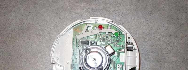
Click to zoom
Application Details
- Equipment Class
- DSC - Part 15 Security/Remote Control Transmitter
- Date of Grant
- Sep 26, 2006
- Application Purpose
- Original Equipment
- Date of Application
- Sep 26, 2006
- Equipment Note
- Alarm Transmitter
- Frequency Range
- 315.00000000 - 315.00000000
- Company
- Nice North America LLC
- Country
- United States
Documents & Files
Document Text
Text extracted from the exhibit documents filed with the FCC. Open a document above to read the original.
Users Manual
SECTION 9 SECTION 9 SECTION 2 LINEAR LLC FCC ID: EF4 SST00113
Attestation Statements
STATEMENT OF ATTESTATION Model: DXS-73 Smoke Alarm Transmitter FCC ID: EF4 SST00113 The equipment under test is a low power battery operated smoke alarm transmitter used with the 315 MHz DVS and PERS family of alarm receivers. Every 1.1 hours this transmitter sends a supervisory signal and battery report. This equipment has been tested in accordance with the requirements contained in the appropriate Commission regulations. To the best of my knowledge, these tests were performed using measurement procedures consistent with industry or commission standards and demonstrate that the equipment complies with the appropriate standards. Each unit manufactured, imported or marketed, as defined in the Commission's regulations, will conform to the sample(s) tested within the variations that can be expected due to quantity production and testing on a statistical basis. I further certify that the necessary measurements were made by Linear LLC, 1950 Camino Vide Roble, Suite 150, Carlsbad, California. 92008. Certified by: __________________________ ___ John W. Kuivinen, P.E. Date: September 12, 2006 Regulatory Compliance Engineer
Attestation Statements
STATEMENT OF ATTESTATION Model: DXS-73 Smoke Alarm Transmitter FCC ID: EF4 SST00113 The equipment under test is a low power battery operated smoke alarm transmitter used with the 315 MHz DVS and PERS family of alarm receivers. Every 1.1 hours this transmitter sends a supervisory signal and battery report. This equipment has been tested in accordance with the requirements contained in the appropriate Commission regulations. To the best of my knowledge, these tests were performed using measurement procedures consistent with industry or commission standards and demonstrate that the equipment complies with the appropriate standards. Each unit manufactured, imported or marketed, as defined in the Commission's regulations, will conform to the sample(s) tested within the variations that can be expected due to quantity production and testing on a statistical basis. I further certify that the necessary measurements were made by Linear LLC, 1950 Camino Vide Roble, Suite 150, Carlsbad, California. 92008. Certified by: __________________________ ___ John W. Kuivinen, P.E. Date: September 12, 2006 Regulatory Compliance Engineer
Block Diagram
SECTION 4 SECTION 4
Block Diagram
SECTION 4 SECTION 4
External Photos
SECTION 9 FRONT VIEW, DXS-73 SMOKE ALARM SECTION 9 REAR VIEW, DXS-73 SMOKE ALARM WITH LOCKING RING IN PLACE SECTION 9 REAR VIEW, DXS-73 SMOKE ALARM FCC / IC LABEL PLACED APPROX. AS SHOWN FCC/IC/UL LABEL PLACED IN THIS AREA
External Photos
SECTION 4 SECTION 4
ID Label/Location Info
FCC IDENTIFICATION LABEL DXS-73 Smoke Alarm LABEL FACSIMILE Linear LLC FCC ID: EF4 SST00113 Model: DXS-73 Product ID: SST00113 IC: 1078A-SST00113 Wireless Smoke Alarm Frequency: 315 MHz This device complies with FCC Part 15 and Industry Canada Rules and Regulations. Operation is subject to the following two conditions: (1) This device may not cause harmful interference, and (2) This device must accept any interference received, including interference that may cause undesired operation.
ID Label/Location Info
SECTION 9 REAR VIEW, DXS-73 SMOKE ALARM FCC / IC LABEL PLACED APPROX. AS SHOWN FCC/IC/UL LABEL PLACED IN THIS AREA
ID Label/Location Info
FCC IDENTIFICATION LABEL DXS-73 Smoke Alarm LABEL FACSIMILE Linear LLC FCC ID: EF4 SST00113 Model: DXS-73 Product ID: SST00113 IC: 1078A-SST00113 Wireless Smoke Alarm Frequency: 315 MHz This device complies with FCC Part 15 and Industry Canada Rules and Regulations. Operation is subject to the following two conditions: (1) This device may not cause harmful interference, and (2) This device must accept any interference received, including interference that may cause undesired operation.
ID Label/Location Info
SECTION 9 REAR VIEW, DXS-73 SMOKE ALARM FCC / IC LABEL PLACED APPROX. AS SHOWN FCC/IC/UL LABEL PLACED IN THIS AREA
Internal Photos
SECTION 5 LINEAR LLC FCC ID: EF4 SST00113
Internal Photos
SECTION 9 DXS-73 INTERIOR VIEW, TRANSMITTER PCB ATTACHED TO MAIN PCB VIA 4 PIN CONNECTOR SEE BOTTOM OF PICTURE SECTION 9 DXS-73 INTERIOR VIEW TRANSMITTER PCB REMOVED FROM CONNECTOR, BACK VIEW OF TRANSMITTER PCB
Internal Photos
SECTION 5 LINEAR LLC FCC ID: EF4 SST00113
Internal Photos
SECTION 9 DXS-73 INTERIOR VIEW, TRANSMITTER PCB ATTACHED TO MAIN PCB VIA 4 PIN CONNECTOR SEE BOTTOM OF PICTURE SECTION 9 DXS-73 INTERIOR VIEW TRANSMITTER PCB REMOVED FROM CONNECTOR, BACK VIEW OF TRANSMITTER PCB
Operational Description
SPECIFICATIONS, DXS-73 1.0 DESCRIPTION The DXS-73 is a single station, battery powered, self-contained, Smoke (CO) Alarm (detector). It has an integral RF transmitter for communicating with Linear's alarm consoles such as the PERS-3600 and DVS-2400. The DXS-73 is suited for apartments, condominiums and other households. This unit is not designed for use in autos, RV's, motor homes, aircraft or boats. 2.0 SMOKE DETECTION The detector uses a patented Biomimetic smoke sensor that is monitored by an electronic micro-controller. An obscuration level smoke measurement is done by pulsed infrared light every 45 seconds. 3.0 FEATURES Low power requirement provides long battery life. Dual function TEST/RESET pushbutton with red LED visual indicator. Automatic SELF-DIAGNOSTIC TEST performed every ten minutes. RF transmitter sends detector status every 1.1 hours. 4.0 DETECTOR SPECIFICATIONS ENCLOSURE: Plastic, 5" diameter, height: 1.5". Material: Noryl, color: off-white. BATTERY DOOR: Open to remove or install battery (includes battery removed warning flag). Battery pull-tab for activation. MOUNTING: Wall or ceiling (near sleeping areas preferred) via locking mounting ring, owner's manual, locking pin, 2 wall anchors and mounting screws are included. POWER: Standard Lithium CR123A 3 volt battery included. Standby current draw: 5-10 uA. Current draw in alarm: 25 mA average. LOW-BATTERY: voltage detection. Threshold 2.7 V. Audible low battery signal: one 10 mSec. audible chirp every 45 seconds. MAINTENANCE: Vacuum dust accumulation annually and perform TEST function weekly. NORMAL OPERATION: On power up, performs self-test & 2 alarm patterns if OK. Red LED indicator (lens of test/reset button) flashes once every 45 seconds. SMOKE DETECTION: Biomimetic smoke sensor. Microcontroller detector operation. Measurement is by pulsed infrared photoelectric every 45 seconds. AUDIBLE ALARM RECOVERY: 3-5 minutes (clear air). Sensor full recovery (Typical): Ambient: 70 ppm 4 hours, 150 ppm 8 hrs, 400 ppm 12 hrs. ALARM: Smoke response concentrations-times, conditions and false-alarm resistance per UL 2034: 70ppm 60-240 minutes, 150ppm 10-50 minutes, 400ppm 4-15 minutes. VISUAL ALARM INDICATOR: Red LED flashes during beeper pulsing pattern. AUDIBLE ALARM: Internal beeper sounds loud repetitive pulsing alarm tone pattern: Pattern cycle: Four 100 mSec. beeps, 100 mSec. apart, followed by 5 seconds of silence. Tone frequency: approx 3.3 kHz. Loudness: 85 dB minimum at 10 ft. TROUBLE SIGNAL: Activated by sensor end-of-life, operational end-of-life or sensor circuit fault found during self-test: TROUBLE (Fault) signal: Double beep and red LED flash every 45 seconds. TEST-RESET: Dual function via a single pushbutton (momentarily-press until beep) that activates the TEST function if unit is not in alarm or the RESET function if unit is in alarm. TEST checks sensor, measuring circuit and horn. Red LED flashes to indicate a test is in progress -about 5 seconds. Two ALARM cycles are sounded if the TEST is OK or TROUBLE signal if not OK. RESET silences the ALARM for 4 minutes. ALARM will sound after this time if recovery has not commenced (clear air). RESET cannot be repeated unless unit has recovered and re-alarms. OUTPUTS: (For connection to RF transmitter - transmitter PCB mounted internally). Power 3.3V, Ground, Signals: Alarm, Test, Low Battery, Fault (trouble). END-OF-LIFE: Non-resetable Trouble signal after 6 years (operational). COMPLIANCE: UL Safety Standard 217. TEMPERATURE: Operating/storage: 0 - 49 deg. C. (32-120F). Not for unconditioned areas, attics, garages, outdoor, RV's, aircraft or boats. HUMIDITY: Operating 15 -95% RH (non-condensing). 5.0 RF TRANSMITTER SPECIFICATIONS PCB Assembly Size: 1.9 x 1.4 x .85 inches. Interfaces with smoke detector PCB via a 4 pin connector. Frequency: 315 MHz, +/- 125 kHz. Encoding Format: DXS Format. System Range: 300 feet, open air, typical. Operating Voltage: 3.3 Volts. Detector supplies regulated voltage to transmitter PCB. Status Supervision: A one-second status signal is transmitted every 1.1 hours, +/- 10%. A one- second alarm transmission is sent immediately when an alarm trigger is sent from the smoke detector and every 20-second interval thereafter for as long as the detector is in an alarm condition. Note: The reset function does not stop these transmissions. Temperature Range 20°C to 60°C.
Operational Description
SPECIFICATIONS, DXS-73 1.0 DESCRIPTION The DXS-73 is a single station, battery powered, self-contained, Smoke (CO) Alarm (detector). It has an integral RF transmitter for communicating with Linear's alarm consoles such as the PERS-3600 and DVS-2400. The DXS-73 is suited for apartments, condominiums and other households. This unit is not designed for use in autos, RV's, motor homes, aircraft or boats. 2.0 SMOKE DETECTION The detector uses a patented Biomimetic smoke sensor that is monitored by an electronic micro-controller. An obscuration level smoke measurement is done by pulsed infrared light every 45 seconds. 3.0 FEATURES Low power requirement provides long battery life. Dual function TEST/RESET pushbutton with red LED visual indicator. Automatic SELF-DIAGNOSTIC TEST performed every ten minutes. RF transmitter sends detector status every 1.1 hours. 4.0 DETECTOR SPECIFICATIONS ENCLOSURE: Plastic, 5" diameter, height: 1.5". Material: Noryl, color: off-white. BATTERY DOOR: Open to remove or install battery (includes battery removed warning flag). Battery pull-tab for activation. MOUNTING: Wall or ceiling (near sleeping areas preferred) via locking mounting ring, owner's manual, locking pin, 2 wall anchors and mounting screws are included. POWER: Standard Lithium CR123A 3 volt battery included. Standby current draw: 5-10 uA. Current draw in alarm: 25 mA average. LOW-BATTERY: voltage detection. Threshold 2.7 V. Audible low battery signal: one 10 mSec. audible chirp every 45 seconds. MAINTENANCE: Vacuum dust accumulation annually and perform TEST function weekly. NORMAL OPERATION: On power up, performs self-test & 2 alarm patterns if OK. Red LED indicator (lens of test/reset button) flashes once every 45 seconds. SMOKE DETECTION: Biomimetic smoke sensor. Microcontroller detector operation. Measurement is by pulsed infrared photoelectric every 45 seconds. AUDIBLE ALARM RECOVERY: 3-5 minutes (clear air). Sensor full recovery (Typical): Ambient: 70 ppm 4 hours, 150 ppm 8 hrs, 400 ppm 12 hrs. ALARM: Smoke response concentrations-times, conditions and false-alarm resistance per UL 2034: 70ppm 60-240 minutes, 150ppm 10-50 minutes, 400ppm 4-15 minutes. VISUAL ALARM INDICATOR: Red LED flashes during beeper pulsing pattern. AUDIBLE ALARM: Internal beeper sounds loud repetitive pulsing alarm tone pattern: Pattern cycle: Four 100 mSec. beeps, 100 mSec. apart, followed by 5 seconds of silence. Tone frequency: approx 3.3 kHz. Loudness: 85 dB minimum at 10 ft. TROUBLE SIGNAL: Activated by sensor end-of-life, operational end-of-life or sensor circuit fault found during self-test: TROUBLE (Fault) signal: Double beep and red LED flash every 45 seconds. TEST-RESET: Dual function via a single pushbutton (momentarily-press until beep) that activates the TEST function if unit is not in alarm or the RESET function if unit is in alarm. TEST checks sensor, measuring circuit and horn. Red LED flashes to indicate a test is in progress -about 5 seconds. Two ALARM cycles are sounded if the TEST is OK or TROUBLE signal if not OK. RESET silences the ALARM for 4 minutes. ALARM will sound after this time if recovery has not commenced (clear air). RESET cannot be repeated unless unit has recovered and re-alarms. OUTPUTS: (For connection to RF transmitter - transmitter PCB mounted internally). Power 3.3V, Ground, Signals: Alarm, Test, Low Battery, Fault (trouble). END-OF-LIFE: Non-resetable Trouble signal after 6 years (operational). COMPLIANCE: UL Safety Standard 217. TEMPERATURE: Operating/storage: 0 - 49 deg. C. (32-120F). Not for unconditioned areas, attics, garages, outdoor, RV's, aircraft or boats. HUMIDITY: Operating 15 -95% RH (non-condensing). 5.0 RF TRANSMITTER SPECIFICATIONS PCB Assembly Size: 1.9 x 1.4 x .85 inches. Interfaces with smoke detector PCB via a 4 pin connector. Frequency: 315 MHz, +/- 125 kHz. Encoding Format: DXS Format. System Range: 300 feet, open air, typical. Operating Voltage: 3.3 Volts. Detector supplies regulated voltage to transmitter PCB. Status Supervision: A one-second status signal is transmitted every 1.1 hours, +/- 10%. A one- second alarm transmission is sent immediately when an alarm trigger is sent from the smoke detector and every 20-second interval thereafter for as long as the detector is in an alarm condition. Note: The reset function does not stop these transmissions. Temperature Range 20°C to 60°C.
Parts List/Tune Up Info
SECTION 9 SECTION 9 SECTION 9 SECTION 9
Parts List/Tune Up Info
SECTION 9 SECTION 9 SECTION 9 SECTION 9
Schematics
SECTION 5 LINEAR LLC FCC ID: EF4 SST00113
Schematics
SECTION 4 LINEAR LLC FCC ID: EF4 SST00113
Schematics
SECTION 5 LINEAR LLC FCC ID: EF4 SST00113
Schematics
SECTION 4 LINEAR LLC FCC ID: EF4 SST00113
Test Report
SECTION 6 TESTING INSTRUMENTATION AND EQUIPMENT LIST SPECTRUM ANALYZERS: H.P. HP8562A 1KHz to 22GHz S/N 2913A03742 Calibrated 04/06 Due 04/07 ANTENNAS: (2) Ailtech DM105A T1 20-200 MHz Tuned Dipole S/N 93412-105 and 93412-114 Calibrated 3/06 Due: 3/07 (2) Ailtech DM105A T2 140-400 MHz Tuned Dipole S/N 93413-113 and 93413-117 Calibrated 3/06 Due: 3/07 (2) Ailtech DM105A T3 400-1000 MHz Tuned Dipole S/N 93413-105 and 93414-111 Calibrated 3/06 Due 3/07 (2) AH Systems SAS-200/511 1-12.4 GHz Log Periodic S/N 118 and 124, P/Ns 2069 (1) AH Systems SAS-200/540 20-330 MHz Biconical S/N 367 P/N 2052 INSTRUMENTATION: H.P. HP8656B RF Generator 100 KHz - 990 MHz S/N A4229590 Calibrated 3/06 Due 3/07 Solar Electronics Line Impedance Stabilization Network, Type 8012-50-R-24-BNC Calibrated: 3/06 S/N 8379585 Due: 3/07 HP 8447D Broadband preamplifier, 0.1-1300 MHz S/N 2443A03660 Calibrated: 3/06 Due: 3/07 Mini-Circuits ZFL-2000 broadband preamplifier, 10-3000 MHz S/N Lin 001 Calibrated: 3/06 Due: 3/07 ACCESSORIES: (2) Ailtech Rulers calibrated in MHz 4 Meter ABS Antenna Mast and Trolley Tektronix C5C Scope Camera Eighty Centimeter Tall, Motorized Wooden Turntable BNC to BNC Cables - as-required (2) 25' RG-214/U Low-loss Coaxial Cable S/N- LIN001 & LIN002 Calibrated: 3/06 Due: 3/07 (2) 3' RG-55/U Low-loss Coaxial Cable, calibarated as part of the preamplifiers. Automatically taken into account when used with the above itemized range preamplifiers. SECTION 6 MEASUREMENT OF RADIO FREQUENCY EMISSION OF CONTROL AND SECURITY ALARM DEVICES FCC RULES PART 15, C63.4-2003 TEST PROCEDURE I. INTRODUCTION As part of a continuing series of quality control tests to ensure compliance with all applicable Rules and Regulations, this enclosure details the test procedures for certain radio control devices. Testing was performed at a test site located on the property of Linear LLC, 1950 Camino Vida Roble, Suite 150, Carlsbad, California 92008-6517. II. MEASUREMENT FACILITY DESCRIPTION The test facility is a specially prepared area adequately combining the desirability of an interference free location with the convenience of nearby 120 volt power outlets, thus completely eliminating the incidence of inverter hash, so often a problem with field measurements. III. DESCRIPTION OF SUPPORTING STRUCTURES For Measuring Equipment - The antenna is supported on a trolley that can be raised and lowered on a mast by means of remote control to any level between 1 meter and 4 meters above the ground. For measurements at 3 meters, an antenna height (center of dipole) of about 1 meter generally yields the greatest field strength. For measurements at 1 meter, an antenna height equal to the device under test generally yields the greatest field strength. Usually, horizontal polarization yields the greatest field strength for both 1 and 3 meter measurements. For Equipment Under Test (EUT) : The equipment to be tested is supported by a wooden turntable at a height of eighty centimeters. A two axis swivel at the top of the turntable permits the unit under test to be manually oriented in the position of maximum received signal strength. The turntable can be rotated by remote control. Test Configuration - All transmitters were located eighty centimeters above ground, at a distance of three meters from the antenna. They were each oriented for maximum radiation by rotating the turntable. The antenna was then moved vertically along the mast for optimum reception in both horizontal and vertical planes. Where no emissions were found, the antenna was also moved to one meter distance to improve system sensitivity. SECTION 6 From 1 GHz to 3 GHz, a Mini-Circuits ZFL-2000 broadband RF preamplifier is used instead of the HP 8447D. In many cases, the antenna is moved in to a distance of 1 meter to enhance test range sensitivity after the 3-meter data is observed. A theoretical 9.54dB improvement is realized. Please see Excel data spreadsheet for details. For a particular device and frequency, the EUT to antenna distance is specified in the Report of Measurements. Correction of Measured Values - The spectrum analyzer calibration is in units of dBm absolute. Published antenna factor, measured cable loss and preamplifier gain are in units of dB. All equipment is referenced to a 50-ohm characteristic impedance; therefore, any impedance terms will factor out of any calculations. Also, balun loss is included in the antenna factor, so this term will not appear in any calculation. To obtain field strength, the reference (50 ohm system) 1 uV = 0 dBuV = -107 dBm is used. For a given frequency: antenna factor, cable loss, preamplifier gain (if used) and a 9.54 dB gain factor (3 meters to 1 meter field strength conversion) when required are factored into the spectrum analyzer reading, resulting in a field strength in units of dBm. Field strength reading (dBm) + 107 dB = dBuV, using 0 dBuV = 1 uV/meter at a specified distance as reference. All of the equipment was calibrated to NBS-traceable factory specifications prior to the date of measurement. IV MEASUREMENT PROCEDURE Transmitters 1. Set the DIP-switch rockers of the transmitter (if needed) to all ON, jam the button in the ON position, and place the transmitter on the test stand. 2. Tune the antenna (if required). 3. Tune the spectrum analyzer. 4. Adjust the antenna height and polarization for peak field strength. 5. Rotate the turntable to orient the transmitter for the highest reading. 6. Record the observed peak emission. 7. Record the screen image (if required). Spectrum Analyzer Control Settings: Tuning: As required Bandwidth 100 KHz for Field Strength, Scan Width: 100 KHz/div (may be different when tuning or adjusting display for photographs) Input Attenuator: 10 dB Scan Time: 50 mSec. sweep Reference Level: 0 dBm Display Mode: Log 10 dB/division Video Filter: OFF Scan Mode: Internal Scan Trigger: Auto SECTION 6 Receivers 1. Place receiver on test stand, apply power. 2. Tune the antenna to the operating frequency t…
Text truncated - open the document above for the full version.
Test Report
SECTION 6 TESTING INSTRUMENTATION AND EQUIPMENT LIST SPECTRUM ANALYZERS: H.P. HP8562A 1KHz to 22GHz S/N 2913A03742 Calibrated 04/06 Due 04/07 ANTENNAS: (2) Ailtech DM105A T1 20-200 MHz Tuned Dipole S/N 93412-105 and 93412-114 Calibrated 3/06 Due: 3/07 (2) Ailtech DM105A T2 140-400 MHz Tuned Dipole S/N 93413-113 and 93413-117 Calibrated 3/06 Due: 3/07 (2) Ailtech DM105A T3 400-1000 MHz Tuned Dipole S/N 93413-105 and 93414-111 Calibrated 3/06 Due 3/07 (2) AH Systems SAS-200/511 1-12.4 GHz Log Periodic S/N 118 and 124, P/Ns 2069 (1) AH Systems SAS-200/540 20-330 MHz Biconical S/N 367 P/N 2052 INSTRUMENTATION: H.P. HP8656B RF Generator 100 KHz - 990 MHz S/N A4229590 Calibrated 3/06 Due 3/07 Solar Electronics Line Impedance Stabilization Network, Type 8012-50-R-24-BNC Calibrated: 3/06 S/N 8379585 Due: 3/07 HP 8447D Broadband preamplifier, 0.1-1300 MHz S/N 2443A03660 Calibrated: 3/06 Due: 3/07 Mini-Circuits ZFL-2000 broadband preamplifier, 10-3000 MHz S/N Lin 001 Calibrated: 3/06 Due: 3/07 ACCESSORIES: (2) Ailtech Rulers calibrated in MHz 4 Meter ABS Antenna Mast and Trolley Tektronix C5C Scope Camera Eighty Centimeter Tall, Motorized Wooden Turntable BNC to BNC Cables - as-required (2) 25' RG-214/U Low-loss Coaxial Cable S/N- LIN001 & LIN002 Calibrated: 3/06 Due: 3/07 (2) 3' RG-55/U Low-loss Coaxial Cable, calibarated as part of the preamplifiers. Automatically taken into account when used with the above itemized range preamplifiers. SECTION 6 MEASUREMENT OF RADIO FREQUENCY EMISSION OF CONTROL AND SECURITY ALARM DEVICES FCC RULES PART 15, C63.4-2003 TEST PROCEDURE I. INTRODUCTION As part of a continuing series of quality control tests to ensure compliance with all applicable Rules and Regulations, this enclosure details the test procedures for certain radio control devices. Testing was performed at a test site located on the property of Linear LLC, 1950 Camino Vida Roble, Suite 150, Carlsbad, California 92008-6517. II. MEASUREMENT FACILITY DESCRIPTION The test facility is a specially prepared area adequately combining the desirability of an interference free location with the convenience of nearby 120 volt power outlets, thus completely eliminating the incidence of inverter hash, so often a problem with field measurements. III. DESCRIPTION OF SUPPORTING STRUCTURES For Measuring Equipment - The antenna is supported on a trolley that can be raised and lowered on a mast by means of remote control to any level between 1 meter and 4 meters above the ground. For measurements at 3 meters, an antenna height (center of dipole) of about 1 meter generally yields the greatest field strength. For measurements at 1 meter, an antenna height equal to the device under test generally yields the greatest field strength. Usually, horizontal polarization yields the greatest field strength for both 1 and 3 meter measurements. For Equipment Under Test (EUT) : The equipment to be tested is supported by a wooden turntable at a height of eighty centimeters. A two axis swivel at the top of the turntable permits the unit under test to be manually oriented in the position of maximum received signal strength. The turntable can be rotated by remote control. Test Configuration - All transmitters were located eighty centimeters above ground, at a distance of three meters from the antenna. They were each oriented for maximum radiation by rotating the turntable. The antenna was then moved vertically along the mast for optimum reception in both horizontal and vertical planes. Where no emissions were found, the antenna was also moved to one meter distance to improve system sensitivity. SECTION 6 From 1 GHz to 3 GHz, a Mini-Circuits ZFL-2000 broadband RF preamplifier is used instead of the HP 8447D. In many cases, the antenna is moved in to a distance of 1 meter to enhance test range sensitivity after the 3-meter data is observed. A theoretical 9.54dB improvement is realized. Please see Excel data spreadsheet for details. For a particular device and frequency, the EUT to antenna distance is specified in the Report of Measurements. Correction of Measured Values - The spectrum analyzer calibration is in units of dBm absolute. Published antenna factor, measured cable loss and preamplifier gain are in units of dB. All equipment is referenced to a 50-ohm characteristic impedance; therefore, any impedance terms will factor out of any calculations. Also, balun loss is included in the antenna factor, so this term will not appear in any calculation. To obtain field strength, the reference (50 ohm system) 1 uV = 0 dBuV = -107 dBm is used. For a given frequency: antenna factor, cable loss, preamplifier gain (if used) and a 9.54 dB gain factor (3 meters to 1 meter field strength conversion) when required are factored into the spectrum analyzer reading, resulting in a field strength in units of dBm. Field strength reading (dBm) + 107 dB = dBuV, using 0 dBuV = 1 uV/meter at a specified distance as reference. All of the equipment was calibrated to NBS-traceable factory specifications prior to the date of measurement. IV MEASUREMENT PROCEDURE Transmitters 1. Set the DIP-switch rockers of the transmitter (if needed) to all ON, jam the button in the ON position, and place the transmitter on the test stand. 2. Tune the antenna (if required). 3. Tune the spectrum analyzer. 4. Adjust the antenna height and polarization for peak field strength. 5. Rotate the turntable to orient the transmitter for the highest reading. 6. Record the observed peak emission. 7. Record the screen image (if required). Spectrum Analyzer Control Settings: Tuning: As required Bandwidth 100 KHz for Field Strength, Scan Width: 100 KHz/div (may be different when tuning or adjusting display for photographs) Input Attenuator: 10 dB Scan Time: 50 mSec. sweep Reference Level: 0 dBm Display Mode: Log 10 dB/division Video Filter: OFF Scan Mode: Internal Scan Trigger: Auto SECTION 6 Receivers 1. Place receiver on test stand, apply power. 2. Tune the antenna to the operating frequency t…
Text truncated - open the document above for the full version.
Test Setup Photos
SECTION 9 TEST SETUP, VERTICAL ORIENTATION SECTION 9 TEST SETUP, VERTICAL ORIENTATION SECTION 9 TEST SETUP, HORIZONTAL ORIENTATION SECTION 9 TEST SETUP - HORIZONTAL POSITION
Test Setup Photos
SECTION 9 TEST SETUP, VERTICAL ORIENTATION SECTION 9 TEST SETUP, VERTICAL ORIENTATION SECTION 9 TEST SETUP, HORIZONTAL ORIENTATION SECTION 9 TEST SETUP - HORIZONTAL POSITION
Contact Information
Applicant
Josh Hansen(Engineering Manager, Regulatory & Compliance)
Technical Contact
Linear LLCJohn W Kuivinen
[email protected]760-438-7138
1950 Camino Vida Roble, Suite 150 · Carlsbad, California · United States
Non-Technical Contact
Linear LLCJohn W Kuivinen
[email protected]760-438-7138
Test Firm
Linear LLCJohn Kuivinen
Technical Specifications
| # | Rule Parts | Frequency Range | Power Output |
|---|---|---|---|
| 1 | 15.231 | 315 MHz - 315 MHz | - |
Other Applications from Nice North America LLC
EF400267
May 19, 2026Edge II Security Panel
Equipment Class
DSS - Part 15 Spread Spectrum TransmitterEF400266
Mar 12, 2026Wireless KVM Extender TX+RX
Equipment Class
NII - Unlicensed National Information Infrastructure TXEF400265
Mar 12, 2026Wireless KVM Extender TX+RX
Equipment Class
NII - Unlicensed National Information Infrastructure TXEF4-FGS223US
Dec 18, 2025DoubleDimmer-Control
Equipment Class
DXX - Part 15 Low Power Communication Device TransmitterEF400247
Jul 01, 2024Digital Transmitter
Equipment Class
DSS - Part 15 Spread Spectrum Transmitter