EF4SST00116Alarm Transmitter
Nice North America LLC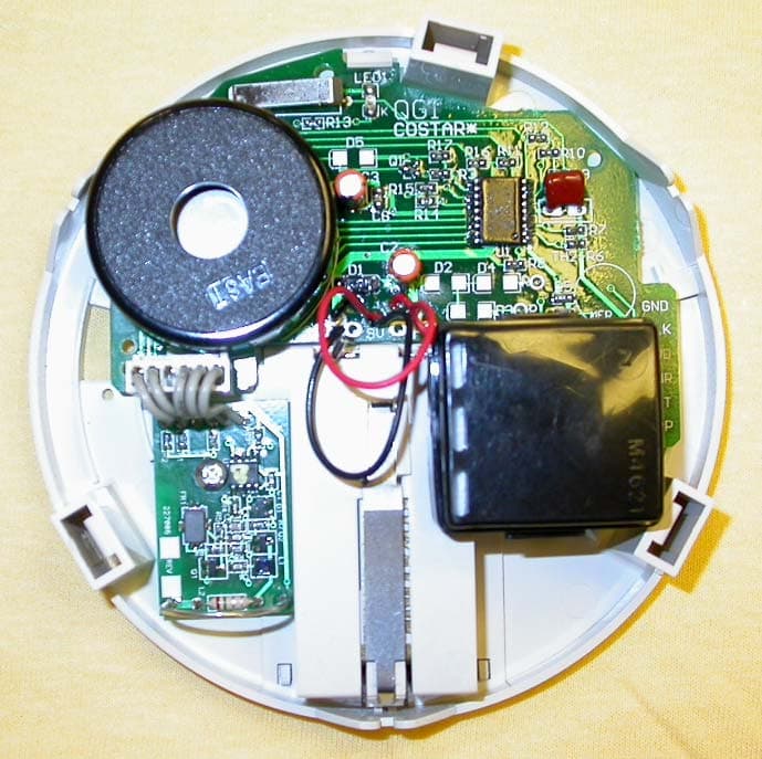
Click to zoom
Application Details
- Equipment Class
- DSC - Part 15 Security/Remote Control Transmitter
- Date of Grant
- Aug 06, 2006
- Application Purpose
- Original Equipment
- Date of Application
- Aug 06, 2006
- Equipment Note
- Alarm Transmitter
- Frequency Range
- 315.00000000 - 315.00000000
- Company
- Nice North America LLC
- Country
- United States
Documents & Files
Document Text
Text extracted from the exhibit documents filed with the FCC. Open a document above to read the original.
Users Manual
SECTION 9 DRAFT - MAY BE REVISED SECTION 9
Block Diagram
SECTION 9 SECTION 9
Cover Letter(s)
OK # Non-Conformity or Comment Submitted Response Respondent / Date of Response X 1 A request for confidentiality was not received. This item is to inform the applicant that certain items may be withheld from public inspection in accordance with 47 CFR §0.457 and §0.459. No response necessary for this item. None requested. Linear 8/4/06 X 2 Please provide a users manual incorporating the statement required by 15.21. While the statement provided in the users manual is similar to that required by the FCC, the statement should be reworded to indicate that the user may no longer operate the equipment. Reference text, “15.21 The users manual or instruction manual for an intentional or unintentional radiator shall caution the user that changes or modifications not expressly approved by the party responsible for compliance could void the user's authority to operate the equipment.” Customer points out legacy approval from FCC and IC. TCB agrees that the statement provided meets the intent of the text of 15.21 since there are no requirements for exact verbiage. Linear 8/4/06 X 3 The FCC requires a separate exhibit be provided which includes test setup photos. This item could not be located in the documentation provided.. Please provide photos of the test setup and arrangement of the equipment during testing. Test setup photos provided. Linear 8/4/06 X 4 Please confirm whether the equipment was tested with a fresh battery in accordance with 15.31(e). Updated test report Linear 8/4/06 X 5 Please confirm whether preliminary testing included maximization of the equipment arrangement in three orthogonal planes in accordance with ANSI C63.4 test procedures. Non-portable device, however EUT emissions maximized according to good engineering practices. Linear 8/4/06 X 6 Please confirm pulse desensitization factor was investigated in accordance with FCC accepted procedure (HP APP note 150-2). Pulse corrections investigated. Linear 8/4/06 X 7 Please confirm that the transmission duration for supervisory signals is less than 2 seconds per hour in accordance with 15.31(a)(4). Customer confirmed: EACH DATA TRANSMISSION CONSISTS OF A 1.0 SECOND DATA SEQUENCE. THIS IS FOR BOTH SUPERVISORY AND ALARM SIGNALS. HOWEVER TO INSURE THAT THE ALARM SIGNALS ARE RECEIVED IN THE PRESENCE OF RF INTERFERENCE, THE ALARM SIGNALS ARE REPEATED EVERY 20 SECONDS AS LONG AS THE CO Linear 8/4/06 ALARM IS IN THE ALARM CONDITION. SUPERVISORY SIGNALS HAVE A DIFFERENT BIT PATTERN THAN AN ALARM SIGNAL. THE ASSOCIATED CONSOLE DETECTS THESE DIFFERENCES IN THE DATA TRANSMISSIONS AND TAKES THE APPROPRIATE ACTIONS (TX AND BATTERY OK OR ALARM DETECTED).”
External Photos
SECTION 9 FRONT VIEW, DXS-80 CARBON MONOXIDE ALARM SECTION 9 FCC and Canada Regulatory Information in this Area REAR VIEW, DXS-80 CARBON MONOXIDE ALARM FCC / IC LABEL PLACED APPROX. AS SHOWN SECTION 9 INTERNAL PCB LAYOUT WITH RF TRANSMITTER PCB SECTION 9 RF TRANSMITTER PCB FRONT AND BACK VIEWS
ID Label/Location Info
SECTION 9 LABEL FACSIMILE LINEAR LLC Product ID: SST00116 Model: DXS-80 Digital Transmitter Frequency: 315 MHz This device complies with FCC Rules Part 15 and Industry Canada Rules and Regulations. Operation is subject to the following two conditions: (1) This device may not cause harmful interference, and (2) This device must accept any interference received, including interference that may cause undesired operation. FCC ID: EF4 SST00116
Internal Photos
SECTION 9 FRONT VIEW, DXS-80 CARBON MONOXIDE ALARM SECTION 9 FCC and Canada Regulatory Information in this Area REAR VIEW, DXS-80 CARBON MONOXIDE ALARM FCC / IC LABEL PLACED APPROX. AS SHOWN SECTION 9 INTERNAL PCB LAYOUT WITH RF TRANSMITTER PCB SECTION 9 RF TRANSMITTER PCB FRONT AND BACK VIEWS
Operational Description
SECTION 9 SPECIFICATIONS, DXS-80 1.0 DESCRIPTION The DXS-80 is a single station, battery powered, self-contained, Carbon Monoxide (CO) Alarm (detector). It has an integral RF transmitter for communicating with Linear's alarm consoles such as the PERS-3600 and DVS-2400. The DXS-80 is suited for apartments, condominiums and other households. This unit is not designed for use in autos, RV's, motor homes, aircraft or boats. 2.0 CO DETECTION The detector uses a patented Biomimetic CO sensor that is monitored by an electronic micro- controller. CO measurement is done by pulsed infrared light every 45 seconds. 3.0 FEATURES Low power requirement provides long battery life. Dual function TEST/RESET pushbutton with red LED visual indicator. Automatic SELF-DIAGNOSTIC TEST performed every ten minutes. RF transmitter sends detector status every 1.1 hours. 4.0 DETECTOR SPECIFICATIONS ENCLOSURE: Plastic, 5" diameter, height: 1.5". Material: Noryl, color: off-white. BATTERY DOOR: Open to remove or install battery (includes battery removed warning flag). Battery pull-tab for activation. MOUNTING: Wall or ceiling (near sleeping areas preferred) via locking mounting ring, owner's manual, locking pin, 2 wall anchors and mounting screws are included. POWER: Standard 9V alkaline battery included. Standby current draw: 5-10 uA. Current draw in alarm: 25 mA average. LOW-BATTERY: voltage detection. Threshold 7.7 V. Audible low battery signal: one 10 mSec. chirp every 45 seconds. MAINTENANCE: Vacuum dust accumulation annually and perform TEST function weekly. NORMAL OPERATION: On power up, performs self-test & 2 alarm patterns if OK. Red LED indicator (lens of test/reset button) flashes once every 45 seconds. CO DETECTION: Biomimetic CO sensor. Microcontroller detector operation. Measurement is by pulsed infrared photoelectric every 45 seconds. AUDIBLE ALARM RECOVERY: 3-5 minutes (clear air). Sensor full recovery (Typical): Ambient: 70 ppm 4 hours, 150 ppm 8 hrs, 400 ppm 12 hrs. ALARM: CO response concentrations-times, conditions and false-alarm resistance per UL 2034: 70ppm 60-240 minutes, 150ppm 10-50 minutes, 400ppm 4-15 minutes. VISUAL ALARM INDICATOR: Red LED flashes during beeper pulsing pattern. SECTION 9 AUDIBLE ALARM: Internal beeper sounds loud repetitive pulsing alarm tone pattern: Pattern cycle: Four 100 mSec. beeps, 100 mSec. apart, followed by 5 seconds of silence. Tone frequency: approx 3.3 kHz. Loudness: 85 dB minimum at 10 ft. TROUBLE SIGNAL: Activated by sensor end-of-life, operational end-of-life or sensor circuit fault found during self-test: TROUBLE (Fault) signal: Double beep and red LED flash every 45 seconds. TEST-RESET: Dual function via a single pushbutton (momentarily-press until beep) that activates the TEST function if unit is not in alarm or the RESET function if unit is in alarm. TEST checks sensor, measuring circuit and horn. Red LED flashes to indicate a test is in progress -about 5 seconds. Two ALARM cycles are sounded if the TEST is OK or TROUBLE signal if not OK. RESET silences the ALARM for 4 minutes. ALARM will sound after this time if recovery has not commenced (clear air). RESET cannot be repeated unless unit has recovered and re-alarms. OUTPUTS: (For connection to RF transmitter - transmitter PCB mounted internally). Power 3.3V, Ground, Signals: Alarm, Test, Low Battery, Fault (trouble). END-OF-LIFE: Non-resetable Trouble signal after 6 years (operational). COMPLIANCE: UL Safety Standard 2075-2034. TEMPERATURE: Operating/storage: 0 -49 deg. C. (32-120F). Not for unconditioned areas, attics, garages, outdoor, RV's, aircraft or boats. HUMIDITY: Operating 15 -95% RH (non-condensing). 5.0 RF TRANSMITTER SPECIFICATIONS PCB Assembly Size: 1.9 x 1.4 x .85 inches. Interfaces with smoke detector PCB via a six-wire connector. Frequency: 315 MHz, +/- 125 kHz. Encoding Format: DXS Format. System Range: 300 feet, open air, typical. Operating Voltage: 3.3 Volts. Detector supplies regulated voltage to transmitter PCB. Status Supervision: A one-second status signal is transmitted every 1.1 hours, +/- 10%. A one- second alarm transmission is sent immediately when an alarm trigger is sent from the CO detector and every 20-second interval thereafter for as long as the detector is in an alarm condition. Note: The reset function does not stop these transmissions. Temperature Range 20°C to 60°C. 6.0 REGULATORY SECTION 9 FCC Part 15 @ 315 MHz. DOC (CSA 6.19 TBD) UL 2034,2075 ULC TBD
Operational Description
SECTION 9 DURATION OF RF TRANSMISSIONS DXS-80 CARBON MONOXIDE ALARM TRANSMITTER This transmitter is normally automatically activated. It is externally triggered using a locally annunciated carbon monoxide alarm. As such, it may be operated continuously by the user (FCC Rules 15.231(a)(4)) during the pendancy of the alarm. When the test push button is pressed, due to battery constraints and an accidental continuous activation causing interference to the system, the maximum length transmission for a single press of the test pushbutton is one second. If the push button is quickly pressed and released, the transmitter will cease transmitting after one second. FCC Rules 15.231 (a)(1) allows no longer than 5 seconds upon the release of a manually activated transmitter. Signed: John W. Kuivinen, P.E. Regulatory Compliance Engineer SECTION 9 Transmitter Duty Cycle Calculations and Time Domain Information DXS Data Format 17 BITS / DATA WORD + 3 BLANK FRAMES BETWEEN WORDS DATA WORD = 20 X 5000 USEC = 100 MILLISECONDS FOR NOMINAL DATA WORD FRAME TWO DATA WORDS SHOWN ABOVE SECTION 9 INDIVIDUAL DATA PULSES, QUATERNARY ENCODED DATA FORMAT 500 MICRO SECONDS FOR EACH DATA PULSE TIME DURATION FOR EACH PULSE IS FIXED 3 DATA PULSES SHOWN ABOVE SECTION 9 Transmitter Duty Cycle Calculations and Time Domain Information DX / DXS Data Format Worst case duty cycle is computed because coded pulse position type A1D modulation is used. Data rate is seventeen 500 uSec pulses in any 100 mSec. time window. During transmission, the transmitter sequentially emits a group of 17 encoded pulses in the form of a pulse-keyed carrier. The data stream consists of preamble and encoded data string. REAL TIME ANALYSIS: Description Total Time "On" Time Total Transmission 17 x 500 uSec. = 8.5 E-3 Sec on time In compliance with FCC Rules 15.35(c), the following duty cycle factor is used for all field strength calculations. A 100 mSec. full word time window is selected with the worst case programmable on time ratio. 8.5 E-3 On time = 8.5 E-2 on time per 100 mSec. time window 100 E-3 Total time 20 log (8.5E-2) = -21.4 dB 20 dB Duty Cycle Ratio (Per FCC Rules)
Schematics
SECTION 5 SECTION 9 SECTION 9 SECTION 9 SECTION 9
Schematics
SECTION 9
Test Report
SECTION 1 LINEAR LLC FCC ID: EF4 SST00116 Application for Certification FCC ID: EF4 SST00116 DXS-80 Carbon Monoxide Alarm Transmitter Submitted by: Linear LLC 1950 Camino Vide Roble, Suite 150 Carlsbad, California 92008 760-438-7138 760-438-7043 (FAX) SECTION 1 LINEAR LLC FCC ID: EF4 SST00116 TABLE OF CONTENTS Product ID: EF4 SST00116 DXS-80 Carbon Monoxide Alarm Transmitter SECTION DESCRIPTION 1. ---------- Table of Contents 2. ---------- Label Facsimile / Statement of Attestation / Summary of Measurements 3. ---------- Equipment Description / Block Diagram 4. ---------- Schematic 5. ---------- Component Assemblies 6. ---------- Equipment List & EMC Test Procedures 7. ---------- Report of Measurements Package 8. ---------- Product Photographs 9. ---------- User Instructions SECTION 2 LINEAR LLC FCC ID: EF4 SST00116 STATEMENT OF ATTESTATION Model: DXS-80 Carbon Monoxide Alarm Transmitter FCC ID: EF4 SST00116 The equipment under test is a low powered carbon monoxide alarm transmitter used with the 315 MHz DVS and PERS family of alarm receivers. Every 1.1 hours this transmitter sends a supervisory signal and battery report. This equipment has been tested in accordance with the requirements contained in the appropriate Commission regulations. To the best of my knowledge, these tests were performed using measurement procedures consistent with industry or commission standards and demonstrate that the equipment complies with the appropriate standards. Each unit manufactured, imported or marketed, as defined in the Commission's regulations, will conform to the sample(s) tested within the variations that can be expected due to quantity production and testing on a statistical basis. I further certify that the necessary measurements were made by Linear LLC, 1950 Camino Vide Roble, Suite 150, Carlsbad, California. 92008. Certified by: __________________________ ___ John W. Kuivinen, P.E. Date: July 18, 2006 Regulatory Compliance Engineer SECTION 2 LINEAR LLC FCC ID: EF4 SST00116 FCC IDENTIFICATION LABEL Model: DXS-80 Carbon Monoxide Alarm Linear Corp. requests authority to use the label as depicted, in accord with Section 2.925(e) of the Commission's Rules, follows herein. LABEL FACSIMILE Linear LLC FCC ID: EF4 SST00116 Model: DXS-80 Product ID: SST00116 IC: 1078A-SST00116 Wireless CO Alarm Frequency: 315 MHz Request for Authorization of Section 2.925(e) The device for which Linear seeks authority is small in size and also requires extensive UL warning text, it therefore does not lend itself to the placement of a FCC label, with associated warnings and instructions, in accord with the FCC labeling requirements. For Linear to produce such a label, the type size would be too small as to be useful to purchasers of the device. Accordingly, Linear requests authority to place upon the device an identification label such as the one depicted herein identified as LABEL FACSIMILE. The additional information which is normally required to be included with the FCC Identification Number in accord with Part 15 of the Commission's Rules shall be located herein as portion of the draft manual attached hereto. Accordingly, in accord with Section 2.925(e) of the Commission's Rules and past Commission decisions, Linear hereby requests authority to label its devices in the manner described herein. The user instruction manual will have the full text of the FCC disclaimer printed in a prominent location as follows: This device complies with FCC Part 15 and Industry Canada Rules and Regulations. Operation is subject to the following two conditions: (1) This device may not cause harmful interference, and (2) This device must accept any interference received , including interference that may cause undesired operation. SECTION 2 LINEAR LLC FCC ID: EF4 SST00116 SECTION 2 LINEAR LLC FCC ID: EF4 SST00116 SECTION 2 LINEAR LLC FCC ID: EF4 SST00116 Summary of Test Results in accord with FCC Rules Part 15 and C63.4-2003 Equipment Model: SST00116 Transmitter Tested to C63.4-1992 Section: FCC Rules 15.231 Field Strength at a distance of 3 meters: 5820 uV/Mtr (- 0.3 dB below limit) @ 315 MHz Peak to Average Ratio: 20 dB - Fixed Duty Cycle Test Conditions: Radiated (Sections 11 & 13) Transmitter: Transmitter Frequency: 315 MHz Nominal (Factory Tuned Only) Bandwidth (20 dB down) < 0.010% of Center Freq. Frequency Tolerance: N/A (Nominal +/- 0.125 MHz) Frequency Stability: N/A (Nominal +/- 0.125 MHz) Transmitter Spurious at 3 meters: 168 uV/Mtr (- 11 dB below limit) (Worst Harmonic) Frequency: 630 MHz Momentary Operation (Yes/No) No Holdover time after manual release: N/A Duration of alarm transmission after activation: 1.0 second transmission every 20 seconds only when the CO detector is in an alarm condition. Attestation: The radio apparatus identified in the application has been subject to all the applicable test conditions specified in FCC Rules Part 15 and all of the requirements of the Standard have been met. Regulatory Compliance Engineer John W. Kuivinen, P.E. ___________________________ Date: __ July 18, 2006 _ SECTION 2 LINEAR LLC FCC ID: EF4 SST00116 Radio Standard Specification Low Power Communication Devices C63.4-2003 and FCC Rules Part 15 1.0 General: 1.2, Exclusions to TV Broadcast Freq. Complies 2.0 Related Documents: Reference Documents for Application: CFR 47, FCC Rules Part 15 3.0 Test Equipment: Supply Voltage: One fresh 9 volt MN1604 alkaline battery Test Equipment List See Section 6 Signal Detector: Peak with 20 dB peak to average conversion. 4.0 Certification and Test Results: Summary of Results per See Section 2 of this Report 5.0 General Technical Requirements: 5.1 Testing Methods: Peak Signal pulse modulated A1D signal. 5.1 Reference Standard: C63.4-2003 (FCC Procedure) 5.2 Modulation: Pulse Positon A1D, AM Modulation 5.3 Type of Antenna: Integral to transmitter PCB - tuned loop 5.4 External Controls: Push Button - Manual Test Activation Button No user serviceable parts except for replacement of battery. 5.5 Acc…
Text truncated - open the document above for the full version.
Test Setup Photos
TEST SETUP, VERTICAL ORIENTATION TEST SETUP, HORIZONTAL ORIENTATION TEST SETUP, HORIZONTAL ORIENTATION TEST SETUP, VERTICAL ORIENTATION
Contact Information
Applicant
Josh Hansen(Engineering Manager, Regulatory & Compliance)
Technical Contact
Linear LLCJohn W Kuivinen
[email protected]760-438-7138
1950 Camino Vida Roble, Suite 150 · Carlsbad, California · United States
Non-Technical Contact
Linear LLCJohn W Kuivinen
[email protected]760-438-7138
Test Firm
Linear LLCJohn Kuivinen
Technical Specifications
| # | Rule Parts | Frequency Range | Power Output |
|---|---|---|---|
| 1 | 15.231 | 315 MHz - 315 MHz | - |
Other Applications from Nice North America LLC
EF400267
May 19, 2026Edge II Security Panel
Equipment Class
DSS - Part 15 Spread Spectrum TransmitterEF400266
Mar 12, 2026Wireless KVM Extender TX+RX
Equipment Class
NII - Unlicensed National Information Infrastructure TXEF400265
Mar 12, 2026Wireless KVM Extender TX+RX
Equipment Class
NII - Unlicensed National Information Infrastructure TXEF4-FGS223US
Dec 18, 2025DoubleDimmer-Control
Equipment Class
DXX - Part 15 Low Power Communication Device TransmitterEF400247
Jul 01, 2024Digital Transmitter
Equipment Class
DSS - Part 15 Spread Spectrum Transmitter