EF4SST00127Security/Remote Control Transmitter
Nice North America LLC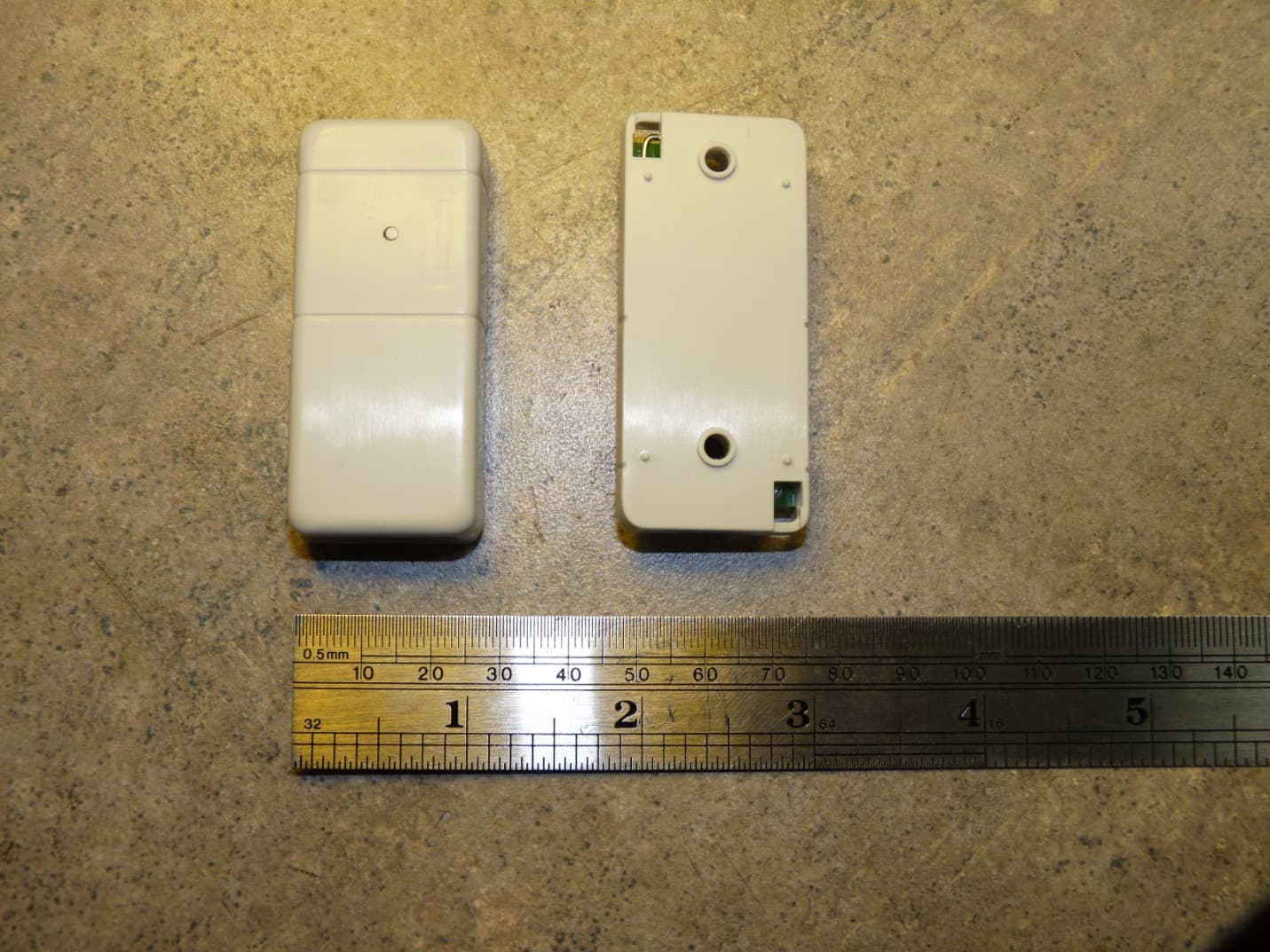
Click to zoom
Application Details
- Equipment Class
- DSC - Part 15 Security/Remote Control Transmitter
- Date of Grant
- Feb 20, 2012
- Application Purpose
- Original Equipment
- Date of Application
- Feb 20, 2012
- Equipment Note
- Security/Remote Control Transmitter
- Frequency Range
- 315.00000000 - 315.00000000
- Company
- Nice North America LLC
- Country
- United States
Documents & Files
Document Text
Text extracted from the exhibit documents filed with the FCC. Open a document above to read the original.
Users Manual
DXS-36AF SUPERVISED DOOR/WINDOW TRANSMITTER Installation Instructions DXS-31AF FEATURES & ACCESSORIES PRINTER’S INSTRUCTIONS: INSTR,INSTL,DXS-36AF - LINEAR P/N: 232812 X4 - INK: BLACK - MATERIAL: 20 LB. MEAD BOND - SIZE: 8.500” X 11.000” - SCALE: 1-1 - SIDE 1 OF 2 PRODUCT DESCRIPTION The DXS-36AF is a battery powered stationary transmitter designed for use with AlarmForce receivers. Triggering the transmitter with its built-in magnetic switch or an external switch sends a digitally coded wireless signal to its companion receiver. The DXS-36AF can send fi ve different signals: alarm, restore, low battery, status, and tamper. The digital code format used in the transmitter features over a million possible codes. The transmitter is pre-coded at the factory to a unique system code, so no fi eld coding is required. The receiver must be programmed to the transmitter’s system code before testing and operation. Refer to the receiver’s instructions for details on programming. In a typical installation, the magnet is mounted on a door or window and the transmitter is mounted on the frame. When the magnet moves more than 1/2” away from the transmitter, an alarm signal is sent. When the magnet returns next to the unit, a restore signal is sent. The magnet is adjustable with four height positions. A 1/4” high magnet spacer is also supplied to snap on to the base of the magnet. Alarms and restores can also be sent from external normally closed contacts wired to the transmitter’s external switch input terminals. The two screw terminals are for connection to one normally closed external contact or multiple normally closed external contacts wired in series. External contacts wire through an opening in the rear of the case. An internal jumper selects which switch input to use. Selections are: internal magnetic switch only, external switch only, or both external and internal switch. Approximately every two hours, the DXS-36AF will send a status signal to the receiver. The status signal updates the receiver to the transmitter’s current condition. By monitoring status signals, the receiver can determine if a transmitter has a low battery or has been removed from the system. Pressing the test button on the case sends a test signal that updates the receiver with the current state of the transmitter. When the test button is pressed, the transmit indicator lights. For two minutes after the test button is pressed, the indicator will light each time the unit sends a signal. The indicator light shines through the transmitter case. The transmitter contains a feature to detect unauthorized tampering. When the transmitter’s case is opened, a tamper signal is sent to the receiver. The transmitter is powered from one Type 2450 3-Volt lithium battery with an expected battery life of up to 5 years. OPENING CASEREMOVE BATTERY PROTECTION STRIP COMPONENT LOCATIONSEXAMPLE INSTALLATIONS ALARMFORCE AlarmForce Industries Inc. 675 Garyray Drive Toronto, ON M9L 1R2, Canada TRANSMITTER MOUNTED ON DOOR JAMB MAGNET MOUNTED ON DOOR MAGNET MOUNTED ON DOOR TRANSMITTER MOUNTED ON WINDOW SILL MAGNET MOUNTED ON WINDOW FRAME SLIDING WINDOW LEFT OPENING DOOR RIGHT OPENING DOOR TRANSMITTER MOUNTED ON DOOR JAMB TRANSMITTER MOUNTED ON WINDOW FRAME MAGNET MOUNTED ON WINDOW SASH STILE DOUBLE-HUNG WINDOW TYPE 2450 BATTERY INPUT SELECT JUMPER TEST BUTTON EXTERNAL SWITCH INPUT SIGNAL INDICATOR NOTE: SIGNAL INDICATOR IS ENABLED FOR TWO MINUTES AFTER PRESSING THE TEST BUTTON TAMPER DETECTOR MOUNTING SCREW HOLES INTERNAL MAGNETIC SWITCH NOTE: BE SURE TO KEEP TAMPER DETECTOR AREA CLEAR OF ANY WIRES PULL BATTERY STRIP TO REMOVE BATTERY PROTECTION STRIP TWIST LIFT OPEN THE CASE TOP BY TWISTING A SMALL FLAT BLADE SCREWDRIVER OR COIN IN THE SLOT ON EITHER END OF THE TRANSMITTER DXS-36AF TRANSMITTER TRANSMITTER SCREWS AND DOUBLE STICK TAPE MAGNET SCREWS AND DOUBLE STICK TAPE ADJUSTABLE MAGNET MAGNET CAN BE MOUNTED UP TO 1/2" FROM LEFT SIDE OF TRANSMITTER 1/2" GAP DISTANCE MAXIMUM SQUEEZE MAGNET TABS TO ADJUST MAGNET HEIGHT (4 POSITIONS) MAGNET ADJUSTMENT TAB (EACH SIDE) TRANSMITTER MOUNTINGADJUSTING MAGNET HEIGHT OPTION JUMPER POSITIONSCONNECTING EXTERNAL CONTACTS PROGRAMMING RECEIVERCHANGING THE BATTERY • The radios are required to comply with IC Rules and Regulations. As such, they have limited transmitter power and therefore limited range. • A receiver cannot respond to more than one transmitted signal at a time and may be blocked by radio signals that occur on or near their operating frequencies, regardless of code settings. • Infrequently used radio links should be tested regularly to protect against undetected interference or fault. • A general knowledge of radio and its vagaries should be gained prior to acting as a wholesale distributor or dealer, and these facts should be communicated to the ultimate users. This device complies with Industry Canada licence-exempt RSS standard(s). Operation is subject to the following two conditions: (1) this device may not cause interference, and (2) this device must accept any interference, including interference that may cause undesired operation of the device. Le présent appareil est conforme aux CNR d’Industrie Canada applicables aux appareils radio exempts de licence. L’exploitation est autorisée aux deux conditions suivantes : (1) l’appareil ne doit pas produire de brouillage, et (2) l’utilisateur de l’appareil doit accepter tout brouillage radioélectrique subi, même si le brouillage est susceptible d’en compromettre le fonctionnement. This device complies with Part 15 of the FCC Rules. Operation is subject to the following two conditions: (1) This device may not cause harmful interference, and (2) This device must accept any interference received, including interference that may cause undesired operation. This equipment has been tested and found to comply with the limits for Class B Digital Device, pursuant to Part 15 of the FCC Rules. These limits are designed to provide reasonable protection against harmful…
Text truncated - open the document above for the full version.
Block Diagram
9.84375 MHz 315 MHz
Cover Letter(s)
LINEAR LLC 1950 CAMINO VIDA ROBLE, SUITE 150, CARLSBAD, CA 92008-6517 PHONE (760) 438-7000 ● (800) 421-1587 ● ENG. FAX (760) 438-7043 MAIL: P.O. BOX 9003 ● CARLSBAD, CA 92018-9003 01 February 2012 Nemko Canada Inc 303 River Road Ottawa, Ontario, Canada K1V 1H2 Attn: Director of Certification FCC ID: EF4 SST00127 Authority to Act as Agent On our behalf, I appoint Alan Laudani of Nemko USA Inc., 2210 Faraday Ave, STE 150, Carlsbad, CA, USA to act as our agent in the preparation of this application for equipment certification. I certify that submitted documents properly describe the device or system for which equipment certification is sought. I also certify that each unit manufactured, imported or marketed, as defined in Federal Communication Commission’s regulations will have affixed to it a label identical to that submitted for approval with this application. For instances where our authorized agent signs the application for certification on our behalf, I acknowledge that all responsibility for complying with the terms and conditions for certification, as specified by Nemko Canada Inc, still resides with Linear L:LC, 1950 Camino Vida Roble, Suite 150, Carlsbad, CA. 92008-6517, USA. This appointment is in effect until December 31, 2012. Sincerely, John W. Kuivinen, P.E. Regulatory Compliance Engineer
Cover Letter(s)
LINEAR LLC 1950 CAMINO VIDA ROBLE, SUITE 150, CARLSBAD, CA 92008-6517 PHONE (760) 438-7000 ● (800) 421-1587 ● ENG. FAX (760) 438-7043 MAIL: P.O. BOX 9003 ● CARLSBAD, CA 92018-9003 Nemko Canada Inc 303 River Road Ottawa, Ontario, Canada K1V 1H2 Attn: Director of Certification Re: Request of Confidentiality for FCC ID#:EF4SST00127 Pursuant to Sections 0.457(d)(I)(ii) and 0.459 of the Commission’s Rules, the Applicant hereby requests confidential treatment of information accompanying as outlined below: NONE OF THE DOCUMENTS NEED TO BE CONSIDERED CONFIDENTIAL. The Applicant understands that pursuant to Rule 0.457(d)(I)(ii), disclosure of this Application and all accompanying documentation will not be made before the date of the Grant for this Application. Dated this 17 of February 2012 Sincerely, John W. Kuivinen, P.E. Regulatory Compliance Engineer, Linear LLC
ID Label/Location Info
FCC IDENTIFICATION LABEL Model: DXS-36AF Door / Window Remote Control Transmitter LABEL FACSIMILE FCC and IC Label Applied In this
Operational Description
1.0 DESCRIPTION The DXS-36AF is a one channel miniature transmitter operating at a frequency of 315 MHz. The DXS-36AF is intended for use in security applications for protection of doors and windows. The transmitter may be used with Alarm Force consoles. Each transmitter comes from the factory sequentially coded. Power is supplied by a single CR2450 3 Volt battery. Battery life is estimated at a minimum of 5 years under typical conditions. 2.0 OPERATION The DXS-36AF is typically activated by opening an internally mounted magnetic reed switch. Terminals for an external normally closed glass break switch are also provided. For testing purposes a carbon button push switch may be used to initially set up the transmitter. A tamper switch is provided if the case top is removed. Upon activation, the LED illuminates and power is provided to IC U3 which outputs a 315 MHz crystal stabilized signal to the antenna. The frequency of U3 is stabilized at a 9.84375 MHz crystal Y1 (315 MHz / 32 = 9.94375 MHz). Data output at U1-6 modulates the input of U3 which transmits the pulse-modulated carrier via the antenna. The transmitter is supervised. It will send a status transmission about every 1.2 hours to show the current status of the battery and contact switches. Any door/window transmission or manually activated transmission will reset the internal status timer back to zero and the transmitter will wait another 1.2 hours to send the next transmission. The test transmission push button requires the use of a special tool (a small pin or wire probe) to access the hidden push button. The test push button or tamper switch is considered to be a manually activated transmission. As such it may operate continuously. However, due to battery limitations, the microprocessor IC has an internal clock that limits manually activated transmissions, even if the switch is held down, to no longer than 10 seconds. Only after the switch is released and then pressed again may another transmission cycle begin. On a brief momentary pressing of the test, tamper or door/window contacts, the microprocessor will power up and complete a minimum of 8 words in the RF data message. This transmission will take approximately 0.8 second. FCC Rules 15.231 (a)(1) allows no longer than 5 seconds upon the release of a manually activated transmitter push button. U2 is a voltage detector IC that sends a low battery signal to the microprocessor U1 if the battery is below 2.5 VDC. 3.0 SPECIFICATIONS Product Identification: DXS-36AF mini transmitter (SST00127). Encoding Format: DX Code for Alarm Force. Encoding Technique: Each transmitter is programmed with the sequential serial transmitter ID number. Number of Channels: One RF Carrier Frequency: 315.0 125 KHz Power Requirements: CR2450 - 3 Volt battery. Visual Indicator: LED. Operating Temperature: 0 C to +70 C. Tested –20 C to 70 C. Size: 2.4" x 1.1" x 0.59". Current Consumption: 7 mA (average) transmitting, 6 uA standby All specifications are nominal unless specified.
Test Report
LINEAR LLC\ FCC ID: EF4 SST00127 IC:1-78A-SST00127 Application for Certification FCC ID: EF4 SST00127 IC: 1078A-SST00127 DXS-36AF Remote Control Transmitter Submitted by: Linear LLC 1950 Camino Vida Roble, Suite 150 Carlsbad, California 92008 760-438-7138 760-438-7043 (FAX) LINEAR LLC\ FCC ID: EF4 SST00127 IC:1-78A-SST00127 SUMMARY OF TEST RESULTS IN ACCORD WITH FCC RULES PART 15, RSS-210 ISSUE 8 DECEMBER 2010 AND C63.4-2003 Equipment Model: SST00127 Transmitter Tested to C63.4-1992 Section: FCC Rules 15.231 Field Strength at a distance of 3 meters: 3845 uV/Mtr (- 3.9 dB below limit) @ 315 MHz Peak to Average Ratio: 20 dB - Worst Case Duty Cycle Test Conditions: Radiated (Sections 11 & 13) Transmitter: Transmitter Frequency: 315 MHz Nominal (Factory Tuned Only) Bandwidth (20 dB down) < 0.020% of Center Freq. Frequency Tolerance: N/A (Nominal +/- 0.125 MHz) Frequency Stability: N/A (Nominal +/- 0.125 MHz) Transmitter Spurious at 3 meters: 471 uV/Mtr (- 2.16 dB below limit) (Worst Harmonic) Frequency: 2520 MHz Momentary Operation (Yes/No) Yes Holdover time after manual release: 0.8 seconds (maximum) Duration of transmission after activation: 0.8 seconds on any single automatic activation Attestation: The radio apparatus identified in the application has been subject to all the applicable test conditions specified in FCC Rules Part 15 and all of the requirements of the Standard have been met. Regulatory Compliance Engineer John W. Kuivinen, P.E. ___________________________ Date: January 31, 2012 LINEAR LLC\ FCC ID: EF4 SST00127 IC:1-78A-SST00127 Radio Standard Specification Low Power Communication Devices C63.4-2003 and FCC Rules Part 15 1.0 General: 1.2, Exclusions to TV Broadcast Freq. Complies 2.0 Related Documents: Reference Documents for Application: CFR 47, FCC Rules Part 15 3.0 Test Equipment: Supply Voltage: Fresh CR2450 3 volt lithium button cell battery Test Equipment List See Section 6 Signal Detector: Peak with 20 dB, peak to average conversion. 4.0 Certification and Test Results: Summary of Results per See Page 1 of this Report 5.0 General Technical Requirements: 5.1 Testing Methods: Peak Signal pulse width modulated A1D signal. 5.1 Reference Standard: C63.4-2003 (FCC Procedure) 5.2 Modulation: Pulse Position, A1D, AM Modulation 5.3 Type of Antenna: Integral to Transmitter PCB 5.4 External Controls: Single reed switch, tamper and manual test push button Optional external switch input. No user serviceable parts except for replacement of battery. 5.5 Accessories: NONE 5.6 TX Bandwidth: <0.020 % (See Section 8) 5.7 Equipment Labels: See Section 2 5.8 Manual Disclaimer: See attached draft copy of manual 5.9 Usage Restrictions: Digital Pulse Code Only LINEAR LLC\ FCC ID: EF4 SST00127 IC:1-78A-SST00127 6.0 Transmitter Characteristics and Tests: 6.1 Momentary Operated Devices: Complies 6.1(a) Types of Signals: Manual Push to Transmit 6.1(a) Automatic Activation: N/A 6.1(a) Five Second Max. upon release: Complies 6.1(b) Maximum Field Strength: 315 MHz = 6042 uV/mtr at 3 meters. 6.1(c) Bandwidth (20 dB down) <0.020 % Complies 6.1(d) Frequency Stability N/A per regulations +/- 0.125 MHz Maximum Error 6.1(e) Reduced Field Strength N/A 6.2 Non-Momentary Operated Devices: N/A 6.2.1 Frequency Bands: Refer to Table 1 6.3 Restricted Bands: Complies 6.5 Pulsed Operation: Complies (20 dB Peak/Average) See Section 8 6.6 Wireline Conducted Emissions: N/A 7.0 Receivers N/A 8.0 Self Certification: N/A 9.0 AC Wireline Conducted Emissions: N/A 10.0 Terminated Measurement Method: N/A 11.0 Radiated Measurement Method: See Section 8 11.1 Measuring Distance: Complies 11.2 Open Field Test Site: Complies, C63.4-2003 11.3 Equipment Test Platform: See Section 8 11.4 Measurement Method: Complies, See Section 8 12.0 DC Power Consumption Methods: N/A 13.0 Near Field Measurement for < 30 MHz: N/A 14.0 Test Report Submission: See Attached LINEAR LLC\ FCC ID: EF4 SST00127 IC:1-78A-SST00127 STATEMENT OF ATTESTATION Model: DXS-36AF Remote Control Transmitter FCC ID: EF4 SST00127\ IC: 1078A-SST00127 The equipment under test is a low powered door/window remote control transmitter used with the Alarm Force series of 315 MHz security consoles. It is designed to send a pulse position encoded RF signal to the receiver when the internal magnetic switch or external switch sensor is opened. Supervisory signals are sent approximately every 1.2 hours. Low battery monitoring functions are provided by this transmitter. This equipment has been tested in accordance with the requirements contained in the appropriate Commission regulations. To the best of my knowledge, these tests were performed using measurement procedures consistent with industry or commission standards and demonstrate that the equipment complies with the appropriate standards. Each unit manufactured, imported or marketed, as defined in the Commission's regulations, will conform to the sample(s) tested within the variations that can be expected due to quantity production and testing on a statistical basis. I further certify that the necessary measurements were made by Linear LLC, 1950 Camino Vida Roble, Suite 150, Carlsbad, California. 92008. Certified by: __________________________ January 31, 2012 John W. Kuivinen, P.E. Date Regulatory Compliance Engineer LINEAR LLC\ FCC ID: EF4 SST00127 IC:1-78A-SST00127 1.0 DESCRIPTION The DXS-36AF is a one channel miniature transmitter operating at a frequency of 315 MHz. The DXS-36AF is intended for use in security applications for protection of doors and windows. The transmitter may be used with Alarm Force consoles. Each transmitter comes from the factory sequentially coded. Power is supplied by a single CR2450 3 Volt battery. Battery life is estimated at a minimum of 5 years under typical conditions. 2.0 OPERATION The DXS-36AF is typically activated by opening an internally mounted magnetic reed switch. Terminals for an external normally closed glass break switch are also provided. For testing purposes a carbon button swit…
Text truncated - open the document above for the full version.
Contact Information
Applicant
Josh Hansen(Engineering Manager, Regulatory & Compliance)
Technical Contact
Linear LLCJohn William Kuivinen
[email protected]760-438-7138
1950 Camino Vida Roble, Suite 150 · Carlsbad · United States
Non-Technical Contact
Linear LLCJohn William Kuivinen
[email protected]760-438-7138
Test Firm
Linear LLCJohn Kuivinen
Technical Specifications
| # | Rule Parts | Frequency Range | Power Output |
|---|---|---|---|
| 1 | 15.231 | 315 MHz - 315 MHz | - |
Other Applications from Nice North America LLC
EF400267
May 19, 2026Edge II Security Panel
Equipment Class
DSS - Part 15 Spread Spectrum TransmitterEF400266
Mar 12, 2026Wireless KVM Extender TX+RX
Equipment Class
NII - Unlicensed National Information Infrastructure TXEF400265
Mar 12, 2026Wireless KVM Extender TX+RX
Equipment Class
NII - Unlicensed National Information Infrastructure TXEF4-FGS223US
Dec 18, 2025DoubleDimmer-Control
Equipment Class
DXX - Part 15 Low Power Communication Device TransmitterEF400247
Jul 01, 2024Digital Transmitter
Equipment Class
DSS - Part 15 Spread Spectrum Transmitter