EFU-OZMO-WM012-A1Dual Band WiFi Direct Transceiver
Ozmo, Inc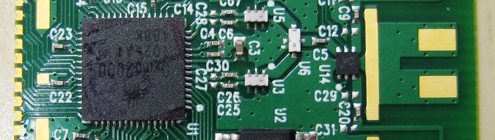
Click to zoom
Application Details
- Equipment Class
- NII - Unlicensed National Information Infrastructure TX
- Date of Grant
- Jul 01, 2012
- Application Purpose
- Original Equipment
- Date of Application
- Jun 28, 2012
- Equipment Note
- Dual Band WiFi Direct Transceiver
- Frequency Range
- 5180.00000000 - 5240.00000000
- Company
- Ozmo, Inc
- Country
- United States
Documents & Files
Document Text
Text extracted from the exhibit documents filed with the FCC. Open a document above to read the original.
Users Manual
User Guide © 2012 Ozmo, Inc. Portions may be covered by one or more of U.S. Patents No. 8,102,871 8,089,982 7,701,271 B1 and 7,826,408 B1. U.S. and foreign patents pending. Page 1 of 9 OZMO2000WM012 Wireless Module User guide APP-0131-AN-V1.0 – May 2012 1 General Description The OZMO2000WM012 Wireless Module is a fully assembled and tested general- purpose module using the OZMO2000 wireless System-on-Chip (SoC). The module contains the OZMO2000 chip, memory, antenna, and all other necessary components to operate the OZMO2000. The memory is preloaded with firmware that is compatible with Windows 7 SoftAP or Wi- Fi CERTIFIED™ Wi-Fi Direct host systems. With modified firmware, the OZMO2000 can support other interfaces, such as I 2 C, PCM/I 2 S a second SPI and GPIO. Contact your Ozmo FAE for assistance with these interfaces. For detailed information on the OZMO2000 component itself, refer to the OZMO2000 datasheet. 2 Features Small, self-contained SMT module On-board memory stores OZMO2000 program image, MAC address and security credentials On-chip regulators allow direct connection to battery or unregulated supply between 1.8V and 3.6V. ( certain limitations may apply depending on module version ) Total module height is 4mm 3 Benefits On-board 8051 processor eliminates need for external micro-controller. Flexible application interfaces included: SPI, UART, I2C, PCM/I2S, GPIOs, LED drivers with PWM support and a General-Purpose ADC. Great battery life thanks to low power radio and systems design. Low latency thanks to agile systems architecture and fast wake up algorithms. OZMO2000WM012 Module User Guide © 2012 Ozmo, Inc. Portions may be covered by one or more of U.S. Patents No. 8,102,871 8,089,982 7,701,271 B1 and 7,826,408 B1. U.S. and foreign patents pending. Page 2 of 9 4 Table of Contents OZMO2000WM012 Wireless Module .............................................................................................. 1 User guide ....................................................................................................................................... 1 1 General Description ................................................................................................................ 1 2 Features .................................................................................................................................. 1 3 Benefits ................................................................................................................................... 1 4 Table of Contents .................................................................................................................... 2 5 Applications information .......................................................................................................... 3 5.1 Application Diagram......................................................................................................... 3 5.2 Using the module ............................................................................................................. 3 6 Pinout / Pin Description ........................................................................................................... 4 6.1 Module Pinout .................................................................................................................. 4 7 Electrical Characteristics ......................................................................................................... 4 7.1 Absolute Maximum Ratings ............................................................................................. 4 7.2 Recommended Operating Conditions ............................................................................. 5 7.3 Terminal Characteristics .................................................................................................. 5 7.4 Radio Characteristics....................................................................................................... 6 7.4.1 Radio Frequencies ................................................................................................... 6 7.4.2 Transmitter ............................................................................................................... 6 7.5 ESD Caution Notice ......................................................................................................... 6 8 Module Floorplan .................................................................................................................... 6 9 Ordering Information ............................................................................................................... 7 10 Regulatory notes ..................................................................................................................... 8 10.1 FCC ID ............................................................................................................................. 9 OZMO2000WM012 Module User Guide © 2012 Ozmo, Inc. Portions may be covered by one or more of U.S. Patents No. 8,102,871 8,089,982 7,701,271 B1 and 7,826,408 B1. U.S. and foreign patents pending. Page 3 of 9 5 Applications information 5.1 Application Diagram Figure 1 Application Diagram 5.2 Using the module The WM012 module is designed to operate with customized embedded firmware programmed into the module by Ozmo Devices which controls the functioning of the radio and the various interfaces. The General Purpose Input-Output pins (referred to as AIO or GPIO pins) are configured and monitored by the firmware. Depending on the programmed functionality, the module will send data over the wireless link corresponding to the inputs received on the AIO pins, or will output digital signals from the AIO pins based on data received over the wireless link. Ozmo application engineers will work with customers to define the desired Input-Output behavior and develop the customized firmware to achieve the desired digital input-output behavior. This has no effect on the radio operat…
Text truncated - open the document above for the full version.
Block Diagram
Ozmo Devices Company Confidential Confidential Page 4 6/14/2012 RD012-1v1 Block Diagram The RF5 port operates on channels 36, 40, 44, 48, 149, 153, 157, 161, and 165 or 5.18GHz to 5.24GHz and 5.745GHz to 5.825GHz The RF2 port operates on channels 1‐ 11 or 2.412GHZ to 2.462GHz
Cover Letter(s)
Page 1 of 1 American TCB 6731 Whittier Avenue, Suite C110 McLean, VA. 22101 RE: FCC Application for Ozmo Inc, FCC ID: EFU-OZMO-WM012-A1 To whom it may concern: The enclosed documents constitute a formal submittal and application for Equipment Authorization for an 802.11abg WiFi Direct Transceiver module pursuant to the following rules: Subpart C of Part 15 of FCC Rules (CFR 47), Intentional Radiators Subpart E of Part 15 of FCC Rules (CFR 47), UNII Devices The application is for a single modular approval. Note, based on the output power, the module is below the RF exposure threshold, and therefore useable in any mobile or portable application. Elliott Laboratories, as duly authorized agent prepared this submittal. A copy of the letter of our appointment as agent is included with the application. If there are any questions or if further information is needed, please contact Elliott Laboratories for assistance. Sincerely, Mark Hill Staff Engineer NTS - Elliott
Cover Letter(s)
Full Modular Approval is being requested for this device. The following paragraphs detail the requirements for modules and explain how the module meets those requirements. Where requirements are not met a justification for a limited modular approval is presented. FCC §15.212 Requirements for Single Modular Transmitters (includes RSS GEN Section 3.2.2) (a) Single modular transmitters consist of a completely self-contained radiofrequency transmitter device that is typically incorporated into another product, host or device. Split modular transmitters consist of two components: a radio front end with antenna (or radio devices) and a transmitter control element (or specific hardware on which the software that controls the radio operation resides). All single or split modular transmitters are approved with an antenna. All of the following requirements apply, except as provided in paragraph (b) of this section. (1) Single modular transmitters must meet the following requirements to obtain a modular transmitter approval. (i) The radio elements of the modular transmitter must have their own shielding. The physical crystal and tuning capacitors may be located external to the shielded radio elements. The shield material is cold rolled steel. It is 8mils thick with a ~3u thick matte tin finish. The shield dimensions are 903mils x 875 mils x 78mils. (ii) The modular transmitter must have buffered modulation/data inputs (if such inputs are provided) to ensure that the module will comply with part 15 requirements under conditions of excessive data rates or over-modulation. Data to the modulation circuit is buffered on the module via the OZMO200 chip (U1 on the schematic). (iii) The modular transmitter must have its own power supply regulation. Power supply regulation is handled within the OZMO2000 (U1 on the schematic). The module and chip are designed to operate directly from a battery. (iv) The modular transmitter must comply with the antenna and transmission system requirements of §§15.203, 15.204(b) and 15.204(c). The antenna must either be permanently attached or employ a “unique” antenna coupler (at all connections between the module and the antenna, including the cable). The “professional installation” provision of §15.203 is not applicable to modules but can apply to limited modular approvals under paragraph (b) of this section. The antennas for this module are chip antennas soldered directly to the board. They are not to be removed or changed. The chip antennas used are the Fractus FR05-S1-NO-1- 004. (v) The modular transmitter must be tested in a stand-alone configuration, i.e., the module must not be inside another device during testing for compliance with part 15 requirements. Unless the transmitter module will be battery powered, it must comply with the AC line conducted requirements found in §15.207. AC or DC power lines and data input/output lines connected to the module must not contain ferrites, unless they will be marketed with the module (see §15.27(a)). The length of these lines shall be the length typical of actual use or, if that length is unknown, at least 10 centimeters to insure that there is no coupling between the case of the module and supporting equipment. Any accessories, peripherals, or support equipment connected to the module during testing shall be unmodified and commercially available (see §15.31(i)). Test data contained in this application is for the device tested in a stand-alone configuration. Radiated spurious emissions data and AC conducted emissions data demonstrating compliance with the requirements of Part 15 of the FCC rules for intentional radiators and RSS GEN/RSS 210 has been provided. (vi) The modular transmitter must be equipped with either a permanently affixed label or must be capable of electronically displaying its FCC identification number. (A) If using a permanently affixed label, the modular transmitter must be labeled with its own FCC identification number, and, if the FCC identification number is not visible when the module is installed inside another device, then the outside of the device into which the module is installed must also display a label referring to the enclosed module. This exterior label can use wording such as the following: “Contains Transmitter Module FCC ID: XYZMODEL1” or “Contains FCC ID: XYZMODEL1.” Any similar wording that expresses the same meaning may be used. The Grantee may either provide such a label, an example of which must be included in the application for equipment authorization, or, must provide adequate instructions along with the module which explain this requirement. In the latter case, a copy of these instructions must be included in the application for equipment authorization. The module is labeled in accordance with the FCC requirements. See the datasheet for instructions on labeling the device into which the module is installed. (B) If the modular transmitter uses an electronic display of the FCC identification number, the information must be readily accessible and visible on the modular transmitter or on the device in which it is installed. If the module is installed inside another device, then the outside of the device into which the module is installed must display a label referring to the enclosed module. This exterior label can use wording such as the following: “Contains FCC certified transmitter module(s).” Any similar wording that expresses the same meaning may be used. The user manual must include instructions on how to access the electronic display. A copy of these instructions must be included in the application for equipment authorization. No electronic display of the FCC identification number is available. (vii) The modular transmitter must comply with any specific rules or operating requirements that ordinarily apply to a complete transmitter and the manufacturer must provide adequate instructions along with the module to explain any such requirements. A copy of these instructions must be in…
Text truncated - open the document above for the full version.
Cover Letter(s)
ozmo devices -nI.r:--r::'-1-1't-r' .t ::. :... .'. -' .' J59ir Iiirst Ila"1,"slrrlt't' llclittl, liuilt 10{} Palo Aito, (rA 1){:J0:j Ph,iu, r I (iir0 irtI lli(ifl li; r:; r1 (i5() :-ll) z(t(l() Authoritv to Act as Agent Date:4124112 American Certification Body, Inc. 6731 Whittier Avenue Suite C110 Mclean, YA 22L01, To Whom It May Concern: Elliott Labs - an NTS Company - is authorized to act on our behalf, until otherwise notified, for applications to American Certification Body, Lrc. (ACB). We certify that we are not subject to denial of federal benefits, that in,;ludes FCL benefits, pursuant to Section 5301 of the Anti-Drug Abuse Act of 1988, 21 U.S.C. 862. Further, no party, as defined in 47 CFR 1.2002 (b). to the applicntion is subject to denial of federal benef,rts, that includes FCC benefits. Thank you, Agency Agreement Expiration Date: 12 months By: Title: VP Engineerins On behalf of: Ozmo" Inc (CompanyName) Telephone:650-s 15-3 5r9 Michael SchwA.!:t;g (Print name)(Signat
Cover Letter(s)
devices Request for Confidentialitv Pursuant to FCC 47 CRF 0.457(d) and 0.459 and IC RSP- 100, Section 10, the applicant requests that a part of the subject FCC application be held confidential. Type of Confidentiality Requested Date: _4123112_ Subject: Confidentiality Request for: EFU-OZMO-WMOI2.AI Exhibit Block Diagrams External Photos Internal Photos Operation Description/Theory of Operation Parts List & Placement/BoM Tune-Up Procedure Schematics Test Setup Photos User's Manual l tr n tr tr tr tr n u *Note: Short Term Short Term Short Term Short Term Short Term Short Term Short Term Short Term Short Term I Permanent I Permanent*l I Fermanent f] Permanent n Permanent X Permanent E Permanent* Ozmo Devices has spent substantial effort in developing this product and it is one ofthe first of its kind in industry. Having the subject information easily available to "competition" would negate the advantage they have achieved by developing this product. Not protecting the details of the design will result in financial hardship. Permanent Confide ntiality : The applicant requests the exhibits listed above as permanently confidential be permanently withheld from public review due to materials that contain trade secrets and proprietary information not customarily released to the public. Sincerely, By: VPEruE ry1 rd-rtft#.* 6LftuJ *tZT3 (Print name) I - The asterisked items (*) require further justification before permanent confidentiality will be allowed. These also currently require review by the FCC under their Permit-But-Ask policy before the grant is issued and can delay completion of an application. Further justification should be added to the note above. One such example for a potted device would be: "The EUT is FULLY potted using a non-removable epoxy based material. Removal of potting material causes irreparable damage to internal circuitry. See photographs exhibits that outline the device before and after potting." 2 - Must be signecl by applicant contact giveu fbr applicarrt on the FC'C'site. or by the authorized agent il'an appropriate autlrorized agent lelter has bcen pror ided. l-etters should be placcd on appropriate lette.rhead. Ozmo Devices, lnc. 2595 Eost Boyshore Road, Suite 700, Polo Alto, CA 94303
ID Label/Location Info
Ozmo Devices Company Confidential Confidential Page 3 5/3/2012 FCC Label The label is a glossy white polyimide film coated with an aggressive permanent acrylic adhesive. It is 12.70 mm x 11.125 mm.
Internal Photos
Ozmo Devices Company Confidential Confidential Page 6 4/27/2012 RD012-1v1 Photos RD012-1v1 Top (no shield)
RF Exposure Info
EMC Test Data Client: Contact: Standard: Test Specific Details General Test Configuration Yes Device complies with Power Density requirements at 20cm separation: Test Engineer: Mark Hill Calculation uses the free space transmission formula: S = (PG)/(4 πd 2 ) Where: S is power density (W/m 2 ), P is output power (W), G is antenna gain relative to isotropic, d is separation distance from the transmitting antenna (m). Summary of Results Maximum Permissible Exposure Objective: The objective of this test session is to perform final qualification testing of the EUT with respect to the specification listed above. Date of Test: 4/25/2012 Mike Schwartz FCC/IC 15.247, 15.407Class: N/A Ozmo, Inc.Job Number: J87039 Model: RD0121v1 T-Log Number: T87048 Account Manager: Sheareen Jacobs 20cm separation: Modifications Made During Testing No modifications were made to the EUT during testing Deviations From The Standard No deviations were made from the requirements of the standard. T87048 (FCC_IC_Radio).xlsMPE CalcPage 1 of 2 EMC Test Data Client: Contact: Standard: Mike Schwartz FCC/IC 15.247, 15.407Class: N/A Ozmo, Inc.Job Number: J87039 Model: RD0121v1 T-Log Number: T87048 Account Manager: Sheareen Jacobs Use: General Antenna: 0.9dBi in 2.4GHz, 4.6dBi in 5GHz Cable AntPower Freq.LossGainat AntEIRP MHzdBmmW*dBdBidBmmW 24124.52.800.94.53.5 24374.73.000.94.73.6 24625.13.200.95.14.0 Cable AntPower Freq.LossGainat AntEIRP MHzdBmmW*dBdBidBmmW 57450.61.104.60.63.3 5785-0.50.904.6-0.52.6 5825-0.60.904.6-0.62.5 Cable AntPower Freq.LossGainat AntEIRP MPE Limit Powerat 20 cmat 20 cm Powe rat 20 cm 1.000 0.0011.000 1.000 at 20 cm Powe rat 20 cmat 20 cm mW/cm^2mW/cm^2 EUTPower Densit y (S)MPE Limit Power Densit y (S)MPE Limit EUTPower Densit y (S) 0.0001.000 0.001 0.0011.000 0.001 mW/cm^2mW/cm^2 0.0011.000 EUT MHzdBmmW*dBdBidBmmW 51804.22.604.64.27.6 52003.42.204.63.46.3 52403.02.004.63.05.7 RF ex posure threshold (per KDB 447498 2) i): 10.3 mW Note - maximum EIRP is less than the RF ex posure threshold. 1.000 mW/cm^2mW/cm^2 0.0011.000 0.001 1.0000.002 T87048 (FCC_IC_Radio).xlsMPE CalcPage 2 of 2
Test Report
EMC Test Report Application for Grant of Equipment Authorization FCC Part 15, Subpart E Model: RD012-1v1 FCC ID: EFU-OZMO-WM012-A1 APPLICANT: Ozmo, Inc. 2595 E. Bayshore Rd Suite 100 Palo Alto, CA 94303 TEST SITE(S): Elliott Laboratories 41039 Boyce Road. Fremont, CA. 94538-2435 IC SITE REGISTRATION #: 2845B-3; 2845B-4, 2845B-5, 2845B-7 REPORT DATE: May 1, 2012 REISSUE DATE: June 15, 2012 FINAL TEST DATES: April 9, 10 and 12, 2012 TOTAL NUMBER OF PAGES: 42 PROGRAM MGR / QUALITY ASSURANCE DELEGATE / TECHNICAL REVIEWER: FINAL REPORT PREPARER: ______________________________ ______________________________ Mark E Hill David Guidotti Staff Engineer Senior Technical Writer Elliott Laboratories is accredited by the A2LA, certificate number 0214.26, to perform the test(s) listed in this report, except where noted otherwise. This report and the information contained herein represent the results of testing test articles identified and selected by the client performed to specifications and/or procedures selected by the client. National Technical Systems (NTS) makes no representations, expressed or implied, that such testing is adequate (or inadequate) to demonstrate efficiency, performance, reliability, or any other characteristic of the articles being tested, or similar products. This report should not be relied upon as an endorsement or certification by NTS of the equipment tested, nor does it represent any statement whatsoever as to its merchantability or fitness of the test article, or similar products, for a particular purpose. This report shall not be reproduced except in full File: R87344 Rev 1 Page 1 Elliott Laboratories -- EMC Department Test Report Report Date: May 1, 2012 Reissue Date: June 15, 2012 File: R87344 Rev 1 Page 2 REVISION HISTORY Rev# Date Comments Modified By - 05-01-2012 First release 1.0 06-15-2012 Updated reference to KDB 789033 MEH Elliott Laboratories -- EMC Department Test Report Report Date: May 1, 2012 Reissue Date: June 15, 2012 File: R87344 Rev 1 Page 3 TABLE OF CONTENTS REVISION HISTORY ................................................................................................................................................ 2 TABLE OF CONTENTS ............................................................................................................................................ 3 SCOPE .......................................................................................................................................................................... 4 OBJECTIVE ................................................................................................................................................................ 4 STATEMENT OF COMPLIANCE ........................................................................................................................... 5 DEVIATIONS FROM THE STANDARDS .............................................................................................................. 5 TEST RESULTS SUMMARY ................................................................................................................................... 6 UNII / LELAN DEVICES ........................................................................................................................................ 6 GENERAL REQUIREMENTS APPLICABLE TO ALL BANDS .......................................................................... 7 MEASUREMENT UNCERTAINTIES .................................................................................................................... 8 EQUIPMENT UNDER TEST (EUT) DETAILS ...................................................................................................... 9 GENERAL ................................................................................................................................................................ 9 ANTENNA SYSTEM .............................................................................................................................................. 9 ENCLOSURE ........................................................................................................................................................... 9 MODIFICATIONS ................................................................................................................................................... 9 SUPPORT EQUIPMENT ......................................................................................................................................... 9 EUT INTERFACE PORTS .................................................................................................................................... 10 EUT OPERATION ................................................................................................................................................. 10 TEST SITE ................................................................................................................................................................. 11 GENERAL INFORMATION ................................................................................................................................. 11 CONDUCTED EMISSIONS CONSIDERATIONS .............................................................................................. 11 RADIATED EMISSIONS CONSIDERATIONS .................................................................................................. 11 MEASUREMENT INSTRUMENTATION ............................................................................................................ 12 RECEIVER SYSTEM ............................................................................................................................................ 12 INSTRUMENT CONTROL COMPUTER ............................................................................................................ 12 FILTERS/ATTENUATORS ...................................................................................…
Text truncated - open the document above for the full version.
Contact Information
Applicant
Michael Schwartz(VP Eng)
Test Firm
Element Materials Technology Fremont NewarkDavid Bare
Technical Specifications
| # | Rule Parts | Frequency Range | Power Output |
|---|---|---|---|
| 1 | 15E | 5.18 GHz - 5.24 GHz | 3.00 mW |
Other Applications from Ozmo, Inc
EFU-OZMO-WM014-B1
Aug 21, 2012WiFi Direct Tranceiver
Equipment Class
NII - Unlicensed National Information Infrastructure TX