EJE-WB0002LifeBook S Series with WLAN WLL4030 and Bluetooth
Fujitsu Client Computing Limited (FCCL)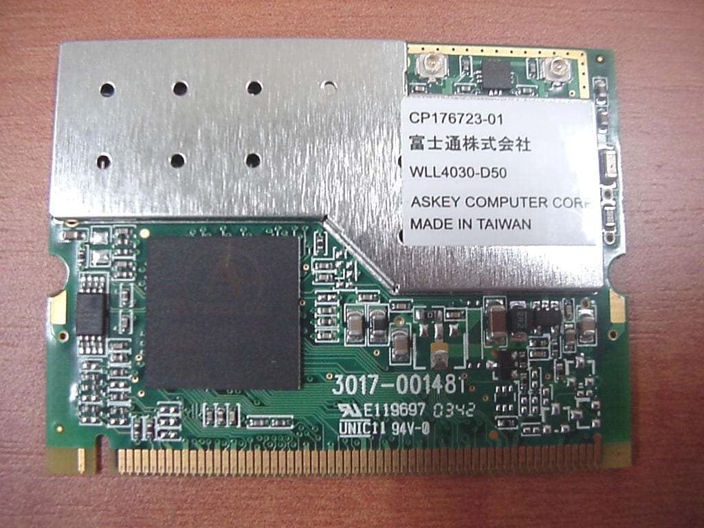
Click to zoom
Application Details
- Equipment Class
- NII - Unlicensed National Information Infrastructure TX
- Date of Grant
- Feb 29, 2004
- Application Purpose
- Original Equipment
- Date of Application
- Feb 29, 2004
- Equipment Note
- LifeBook S Series with WLAN WLL4030 and Bluetooth
- Frequency Range
- 5725.00000000 - 5825.00000000
- Country
- Japan
Documents & Files
Document Text
Text extracted from the exhibit documents filed with the FCC. Open a document above to read the original.
Users Manual
FCC ID: EJE-WB0002 (IC: 337J-WB0002) Report No. M040124_Certification_Onion_Atheros_2.4_BT EMC Technologies Pty Ltd – 57 Assembly Drive, Tullamarine VIC 3043 Australia www.emctech.com.au EMC Technologies Report Number: M040124_Cert_Onion_Atheros_2.4_BT APPENDIX O – USER MANUAL Test Sample – LifeBook S Series, Model: S7010D (Onion) with WLAN Module – Atheros (11a+b/g), Model: WLL4030 & Bluetooth Module, Model UGXZ5-102A Copyright Copyright Fujitsu Computer Systems Corporation has made every effort to ensure the accuracy and completeness of this document; however, as ongoing development efforts are continually improving the capabilities of our products, we cannot guarantee the accuracy of the contents of this document. We disclaim liability for errors, omissions, or future changes. Fujitsu, the Fujitsu logo, and LifeBook are registered trademarks of Fujitsu Limited. The following are registered trademarks of IBM Corporation: IBM, IBM PC AT, IBM PS/2. The following are registered trademarks of Microsoft Corporation: MS, MS-DOS, Windows. PCMCIA is a trademark of the Personal Computer Memory Card International Association. Earthlink is a registered trademark of EarthLink Network, Inc. Intel and Pentium are registered trademarks of Intel Corporation or its subsidiaries in the United States and other countries. The Bluetooth trademark is owned by Bluetooth SIG, Inc., USA. Adobe Acrobat Reader is a registered trademark of Adobe Systems, Inc. Netscape 7.0 is a registered trademark of Netscape Communications Corporation. PowerQuest and Drive Image are registered trademarks of PowerQuest Corporation. Norton AntiVirus is a registered trademark of Symantec Corporation. BayManager is a registered trademark of Softex, Inc. The DVD player found in some models of the LifeBook notebook incorporates copyright protection technology that is protected by method claims of certain U.S. patents and other intellectual property rights owned by Macrovision Corporation and other rights users. Use of this copyright protection technology must be authorized by Macrovision Corporation, and is intended for home and other limited viewing uses only unless authorized by Macrovision Corporation. Reverse engineering or disas- sembly is prohibited. Dolby Headphone manufactured under license from Dolby Laboratories. Dolby, Pro Logic, and the double-D symbol are trademarks of Dolby Laboratories. Copy- rights 1992-1999 Dolby Laboratories. All rights reserved. All other trademarks mentioned herein are the property of their respective owner s. © Copyright 2004 Fujitsu Computer Systems Corpora- tion. All rights reserved. No part of this publication may be copied, reproduced, or translated, without prior written consent of Fujitsu. No part of this publication may be stored or transmitted in any electronic form without the written consent of Fujitsu. B5FH-9991-01EN-00. Warning Handling the cord on this product will expose you to lead, a chemical known to the State of California to cause birth defects or other reproductive harm. Wash hands after handling. DECLARATION OF CONFORMITY according to FCC Part 15 Responsible Party Name:Fujitsu Computer Systems Corporation Address: 1250 E. Arques Avenue, M/S 122 Sunnyvale, CA 94085 Telephone:(408) 746-6000 Declares that product:Base Model Configurations: LifeBook S7010 notebook LifeBook S7010D notebook Complies with Part 15 of the FCC Rules. This device complies with Part 15 of the FCC rules. Operations are subject to the following two conditions: (1) This device must not be allowed to cause harmful interference, (2) This device must accept any interference received, including interference that may cause undesired operation. S Series.book Page 1 Thursday, February 12, 2004 4:15 PM LifeBook S7000 Notebook S Series.book Page 2 Thursday, February 12, 2004 4:15 PM Table of Contents Fujitsu LifeBook ® S7000 Notebook Table of Contents 1 PREFACE Preface About This Guide . . . . . . . . . . . . . . . . . . . . . . . . . 1 Fujitsu Contact Information . . . . . . . . . . . . . . . . . 1 Limited Warranty . . . . . . . . . . . . . . . . . . . . . . . . . 1 2 ABOUT YOUR LIFEBOOK Overview Unpacking . . . . . . . . . . . . . . . . . . . . . . . . . . . . . . 5 Locating the Controls and Connectors Top and Front Components . . . . . . . . . . . . . . . . . 6 Left-Side Panel Components . . . . . . . . . . . . . . . . 7 Right-Side Panel Components . . . . . . . . . . . . . . . 8 Back Panel Components . . . . . . . . . . . . . . . . . . . . 9 Bottom Components . . . . . . . . . . . . . . . . . . . . . 10 Status Indicator Panel Power Indicator . . . . . . . . . . . . . . . . . . . . . . . . . 11 AC Adapter Indicator . . . . . . . . . . . . . . . . . . . . . 11 Battery Level Indicators . . . . . . . . . . . . . . . . . . . 11 Battery Charging Indicators . . . . . . . . . . . . . . . . 12 DVD/CD-RW/CD-ROM Drive Access Indicator . . . . . . . . . . . . . . . . . . . . . . 12 Hard Drive or Removable Media Drive Access Indicator . . . . . . . . . . . . 12 PC Card Access Indicator . . . . . . . . . . . . . . . . . . 12 NumLk Indicator. . . . . . . . . . . . . . . . . . . . . . . . . 12 CapsLock Indicator . . . . . . . . . . . . . . . . . . . . . . . 12 ScrLk Indicator . . . . . . . . . . . . . . . . . . . . . . . . . . 12 Security Indicator . . . . . . . . . . . . . . . . . . . . . . . . 12 Keyboard Using the Keyboard . . . . . . . . . . . . . . . . . . . . . . 13 Numeric Keypad. . . . . . . . . . . . . . . . . . . . . . . . . 13 Windows Keys . . . . . . . . . . . . . . . . . . . . . . . . . . 13 Cursor Keys . . . . . . . . . . . . . . . . . . . . . . . . . . . . 13 Function Keys. . . . . . . . . . . . . . . . . . . . . . . . . . . 14 Touchpad Pointing Device Clicking . . . . . . . . . . . . . . . . . . . . . . . . . . . . . . . 15 Double-Clicking . . . . . . . . . . . . . . . . . . . . . . . . . 15 Dragging . . . . . . . . . . . . . . . . . . . . . . . . . . . . . . 16 Touchpad Control Adjustment . . . . . . . . . . . .…
Text truncated - open the document above for the full version.
Users Manual
57 Troubleshooting LifeBook notebook fails to recognize DVD/CD-RW/ CD-ROM’s. (continued) DVD/CD-RW/CD-ROM is dirty or defective. Wipe DVD/CD-RW/CD-ROM with a non-abrasive CD cleaning cloth and reinsert. It if still will not work try another DVD/CD-RW/CD-ROM in the drive. The DVD/CD-RW/CD- ROM Access indicator on the Status Indicator Panel blinks at regular intervals when no DVD/CD-RW/ CD-ROM is in the tray or the DVD/CD-RW/CD- ROM drive is not installed. The Windows DVD/CD-RW/ CD-ROM auto insertion func- tion is active and is checking to see if a DVD/CD-RW/CD- ROM is ready to run. This is normal. However, you may disable this feature. Port Replicator Problems Note: Be sure to power down your LifeBook notebook before adding a printer to the Port Replicator parallel port. LifeBook notebook does not turn on when installed in the optional Port Replicator Port Replicator AC adapter is not plugged in. Provide power to the Port Replicator. Notebook is not properly seated in the Port Replicator. Remove and re-dock your LifeBook notebook. Floppy Disk Drive Problems You cannot access your floppy disk. You tried to write to a write protected floppy disk. Eject the floppy disk and set it to write enable. (See Preparing a Disk for Use on page 42 for more information) Floppy disk is not loaded correctly. Eject floppy disk, check orientation and re-insert. (See Ejecting a Disk on page 42 for more information) The floppy disk drive may not be properly installed. Remove and re-install your floppy disk drive. Security is set to protect access to floppy disk data. Verify your password and security settings. Hard Drive Problems You cannot access your hard drive. The setup utility is incorrectly set for your internal (Primary Master) or optional second hard drive (Primary Slave). Revise BIOS settings to set both Primary Master and Primary Slave correctly. (See BIOS Setup Utility on page 29 for more information) The wrong drive designator was used by an application when a bootable CD-ROM was used to start the notebook. Verify drive designator used by application is in use by the operating system. When the operating system is booted from a CD, drive designations are automatically adjusted. Security is set so your oper- ating system cannot be started without a password. Verify your password and security settings. Keyboard or Mouse Problems The built-in keyboard does not seem to work. The notebook has gone into Suspend mode. Push the Power/Suspend/Resume button. Your application has locked out your keyboard. Try to use your integrated pointing device to restart your system. ProblemPossible CausePossible Solutions S Series.book Page 57 Thursday, February 12, 2004 4:15 PM 58 LifeBook S7000 Notebook You have installed an external keyboard or mouse, and it does not seem to work. Your external device is not properly installed. Re-install your device. (See Device Ports on page 50 for more information) Your operating system software is not setup with the correct software driver for that device. Check your device and operating system docu- mentation and activate the proper driver. Your mouse or keyboard is connected to the wrong PS/2 port on the optional Port Replicator. Plug the mouse into the PS/2 Mouse port and the external keyboard or numeric key pad into the PS/2 Keyboard port. (See PS/2 Port on page 51 for more information) You have connected an external keyboard or a mouse and it seems to be locking up the system. Your operating system software is not setup with the correct software driver for that device. Check your device and operating system documentation and activate the proper driver. Your system has crashed.Try to restart your notebook. I Memory Problems Your Power On screen, or Main menu of the BIOS setup utility information, does not show the correct amount of installed memory. Your memory upgrade module is not properly installed. Remove and re-install your memory upgrade module. (See Memory Upgrade Module on page 45 for more information) You have a memory failure.Check for Power On Self Test (POST) messages. (See Power On Self Test Messages on page 64 for more information) Modem Problems Messages about modem operation. Messages about modem operation are generated by whichever modem application is in use. See your application software documentation for additional information. Parallel, Serial, and USB Device Problems You have installed a parallel port device, a serial port device or a USB device. Your LifeBook notebook does not recognize the device, or the device does not seem to work properly. The device is not properly installed. Remove and re-install the device. (See Device Ports on page 50 for more information) The device may have been installed while an application was running, so your notebook is not aware of its installation. Close the application and restart your notebook. Your device may not have the correct software driver active. See your software documentation and activate the correct driver. You may have the wrong I/O address selected for your device. See your device documentation and software docu- mentation to determine the required I/O address. Change the settings in the BIOS setup utility. (See BIOS Setup Utility on page 29 for more information) Your device and another device are assigned the same I/O address. Check all I/O addresses located within the BIOS setup utility and any other installed hardware or software to make sure there are no duplications. Parallel port is set to output only. Check parallel port setting in the BIOS and set to bi-directional or ECP. ProblemPossible CausePossible Solutions S Series.book Page 58 Thursday, February 12, 2004 4:15 PM 59 Troubleshooting PC Card Problems A card inserted in the PC Card slot does not work or is locking up the system. The card is not properly installed. Remove and re-install the card. (See PC Cards on page 43 for more information) The card may have been installed while an application was running, so your notebook is not aware of its i…
Text truncated - open the document above for the full version.
Block Diagram
Figure WLL4030 Block diagram
Cover Letter(s)
Federal Communications Commission Equipment Authorization Division Application Processing Branch 7435 Oakland Mills Road Columbia, MD 21045 Date: 16 th February 2004 Reference: FCC ID: EJE-WB0002 Subject: Request for Confidentiality for FCC Certification Application Company: FUJITSU Ltd Test Sample: Mini-PCI Wireless LAN Module (Atheros (11a+b/g)) & Bluetooth Device installed in Host - Fujitsu's LifeBook S Series PC, Model S7010D (Onion) Pursuant to Rule 47 CFR, Chapter 1, Section 0.457(d)(1)(ii), FUJITSU requests that prior to the equipment authorization grant for the (test sample), the entire application be classified and deemed confidential by the Federal Communications Commission (FCC) and as such be withheld from public inspection. As per 47 CFR, Chapter 1, Section 0.457, the exhibits tendered for the purpose of this grant, contain details of trade secrets and technical data that is not made available to competitors and the general public. This information is treated in a confidential manner by FUJITSU and guarded from disclosure to our competitors. The exhibits outlined below are not routinely made available to FUJITSU staff, with such access granted only to those specifically involved with this particular project. They contain information detailing the unique technology and circuitry of the product that would be of significant benefit to our competitors. All employees treat this technical data in a confidential manner. The manufacture of this product has taken place after an extensive research and development process that has seen the company invest a considerable amount of time and money. The time and effort taken has enabled the product to meet the specific demands of the competitive market for which it is intended and it would be therefore detrimental to allow competitors easy access to design and development details. Apart from a limited number of employees, the information has previously only been disclosed to the Test House responsible for conducting testing and authorized to act as our agent during the certification process. Pursuant to 47CFR Chapter 1, Section 0.459, post-grant confidentiality is requested for the following items, ensuring that this material continue to be withheld from public inspection following the grant. Exhibits – Technical PCB Layouts, Technical Schematic Circuit Diagrams, Detailed Antenna Information Sincerely Yours, Kanbe Katsuhito Fujitsu Japan Mobile Computing Division FUJITSU LIMITED 1405 Ohmaru, Inagi-shi, Tokyo 206-8503, Japan Tel(+81-42)370-7632 FAX(+81-42)370-7708 Mobile Computing Division Product Type: - Low power transmitter (intentional radiator)
Cover Letter(s)
Response to TCB Findings 1. Please explain with an example; the conversion calculation of -27dBm/MHz into 68.3dBuV/m (at 3m) as listed on page 15 of the test report. With a resolution bandwidth of 1 MHz, - 27 dBm/MHz converted into Watts = 2 uW. For calculating field strength Field Strength (E) = 20LOG(Square root (30 x P) / D*10^(-6)) Where P = 2*10^(-6)watts & D = 3m. Therefore E = 68.3dBuV/m (at 3m) 2. Was the public notice DA 02-2138 used for the testing? If so please specify which methods in the document have been used for "Peak conducted output power", "PPSD" and "Peak Excursion Measurements". We have been using the latest Part 15 regulations (Subpart E, Section 15.407) released by the Commission as of December 8, 2003 and Guidance on Measurements for Digital Transmission Systems Section 15.247. After reviewing the DA 02-2138 document, we noticed that incidentally, ---The measurements for "PPSD" were performed as per method 2 of DA 02-2138. ---The measurements for "Peak conducted output power" were performed with a resolution bandwidth of 10MHz instead of 1MHz as per the DA 02-2138. Our tested method would yield a higher Peak output power than 1MHz bandwidth measurement as per method 3 of DA 02-2138. ---The measurements for "Peak Excursion Measurements" were performed with a RBW = 1MHz and VBW = 3MHz (for trace 1) as described in DA 02-2138 and a RBW = 1MHz and VBW = 300kHz (for trace 2). 3. Please describe how the WLAN complies with the requirements of 15.407(c). Data Transmission is always initiated by software, which is then passed down through the MAC, through the digital and analog baseband, finally to the RF chip. Several special packets (ACKs, CTS, PSPoll, etc...) are initiated by the MAC. These are the only ways the digital baseband portion will turn on the RF transmitter, which then turns off at the end of the packet. Therefore, the transmitter will be ON only while one of the four mentioned packets are being transmitted.
External Photos
FCC ID: EJE-WB0002 (IC: 337J-WB0002) Report No. M040124_Cert_Onion_Atheros_5.2_BT EMC Technologies Pty Ltd – 57 Assembly Drive, Tullamarine VIC 3043 Australia www.emctech.com.au EMC Technologies Report Number: M040124_Cert_Onion_Atheros_5.2_BT APPENDIX B1 – Test Sample External Photographs FCC ID: EJE-WB0002 (IC: 337J-WB0002) Report No. M040124_Cert_Onion_Atheros_5.2_BT EMC Technologies Pty Ltd – 57 Assembly Drive, Tullamarine VIC 3043 Australia www.emctech.com.au WLAN Module – Atheros (11a+b/g), Model WLL4030 FCC ID: EJE-WB0002 (IC: 337J-WB0002) Report No. M040124_Cert_Onion_Atheros_5.2_BT EMC Technologies Pty Ltd – 57 Assembly Drive, Tullamarine VIC 3043 Australia www.emctech.com.au Host PC - LifeBook S Series, Model S7010D (Onion)
ID Label/Location Info
FCC ID: EJE-WB0002 (IC: 337J-WB0002) Report No. M40124_Cert_Onion_Atheros_5.2_BT EMC Technologies Pty Ltd – 57 Assembly Drive, Tullamarine VIC 3043 Australia www.emctech.com.au EMC Technologies Report Number: M040124_Cert_Onion_Atheros_5.2_BT FCC LABELLING – Additional details Host PC - LifeBook S Series, Model: S7010, S7010DD (Onion) Label location FCC ID: EJE-WB0002 (IC: 337J-WB0002) Report No. M40124_Cert_Onion_Atheros_5.2_BT EMC Technologies Pty Ltd – 57 Assembly Drive, Tullamarine VIC 3043 Australia www.emctech.com.au Label to be adhered to base of LifeBook S Series, Model S7010, S7010D (Onion) Label location
ID Label/Location Info
Nile Nile
Internal Photos
FCC ID: EJE-WB0002 (IC: 337J-WB0002) Report No. M040124_Cert_Onion_Atheros_5.2_BT EMC Technologies Pty Ltd – 57 Assembly Drive, Tullamarine VIC 3043 Australia www.emctech.com.au EMC Technologies Report Number: M040124_Cert_Onion_Atheros_5.2_BT APPENDIX B3 WLAN & Antenna Location Photographs FCC ID: EJE-WB0002 (IC: 337J-WB0002) Report No. M040124_Cert_Onion_Atheros_5.2_BT EMC Technologies Pty Ltd – 57 Assembly Drive, Tullamarine VIC 3043 Australia www.emctech.com.au APPENDIX B3 – WLAN & Antenna Location Atheros WLAN location WLAN ANTENNA LOCATION FCC ID: EJE-WB0002 (IC: 337J-WB0002) Report No. M040124_Cert_Onion_Atheros_5.2_BT EMC Technologies Pty Ltd – 57 Assembly Drive, Tullamarine VIC 3043 Australia www.emctech.com.au APPENDIX B3 – WLAN & Antenna Location WLAN Antenna location – exploded view Atheros WLAN
Internal Photos
FCC ID: EJE-WB0002 (IC: 337J-WB0002) Report No. M040124_Cert_Onion_Atheros_5.2_BT EMC Technologies Pty Ltd – 57 Assembly Drive, Tullamarine VIC 3043 Australia www.emctech.com.au EMC Technologies Report Number: M040124_Cert_Onion_Atheros_5.2_BT APPENDIX B4 – Test Sample Photographs (internal) FCC ID: EJE-WB0002 (IC: 337J-WB0002) Report No. M040124_Cert_Onion_Atheros_5.2_BT EMC Technologies Pty Ltd – 57 Assembly Drive, Tullamarine VIC 3043 Australia www.emctech.com.au Test Sample WLAN Module – Atheros (11a+b/g), Model WLL4030 FCC ID: EJE-WB0002 (IC: 337J-WB0002) Report No. M040124_Cert_Onion_Atheros_5.2_BT EMC Technologies Pty Ltd – 57 Assembly Drive, Tullamarine VIC 3043 Australia www.emctech.com.au Test Sample Bluetooth Module FCC ID: EJE-WB0002 (IC: 337J-WB0002) Report No. M040124_Cert_Onion_Atheros_5.2_BT EMC Technologies Pty Ltd – 57 Assembly Drive, Tullamarine VIC 3043 Australia www.emctech.com.au Host PC LifeBook S Series, Model S7010D (Onion) FCC ID: EJE-WB0002 (IC: 337J-WB0002) Report No. M040124_Cert_Onion_Atheros_5.2_BT EMC Technologies Pty Ltd – 57 Assembly Drive, Tullamarine VIC 3043 Australia www.emctech.com.au Host PC LifeBook S Series, Model S7010D (Onion) – exploded view (WLAN location)
Operational Description
Page 1 of 7 Last printed 7/4/2003 6:05 PM Askey 802.11a/b/g, 802.11b/g WLAN card Functional Description The Askey 802.11a/b/g, 802.11b/g WLAN card Designs are based on Atheros AR5002X chip set which implements IEEE 802.11a, IEEE 802.11b, and IEEE 802.11g WLAN solutions or the AR5002G chipset for IEEE 802.11b/g-only solutions. The chipsets consist of the following: z AR5212An all-CMOS, IEEE 802.11a/802.11b/802.11g MAC/baseband processor, and CardBus/PCI bus interface. z AR5112 Radio-on-a-Chip (RoC) An all-CMOS IEEE 802.11a/802.11b/802.11g, single-chip radio transceiver that converts RF signals to the baseband range for use by the AR5212. The AR5112 offers fully integrated transmitter, receiver, and frequency synthesizer functions; eliminating the need for external voltage controlled oscillators (VCOs) and surface acoustic wave (SAW) filters. z AR2112 Radio-on-a-Chip (RoC) An all-CMOS IEEE 802.11b/802.11g, single-chip radio transceiver that converts RF signals to the baseband range for use by the AR5212. The AR2112 offers fully integrated transmitter, receiver, and frequency synthesizer functions; eliminating the need for external voltage controlled oscillators (VCOs) and surface acoustic wave (SAW) filters. When combined into a single design, the AR5002X (AR5112 and AR5212) chip set enables a low-cost, compact multi-mode solution that easily fits on a PC Card or Mini PCI design. For IEEE 802.11g-only implementations, the WLAN card may be used by not populating the IEEE 802.11a radio section, replacing the AR5002X chip set with a AR5002G (AR2112 and AR5212) chip set. By doing this, a single PCB may be used for triple band designs, and single band designs. AR5002 STA Block Diagram The AR5002X chipset provides a highly integrated IEEE 802.11a, IEEE 802.11b, and IEEE 802.11g solution, as shown by the block diagram in Figure 1-1. Page 2 of 7 Last printed 7/4/2003 6:05 PM Figure 1-1. AR5002 STA Radio Block Diagram The AR5212 is the origin and destination for all the front-end signals. Both transmit (Tx) and receive (Rx) signals are transferred by the AR5112 to either a 5 GHz front-end, or to a 2.4 GHz front end. The 5 GHz and the 2.4 GHz front ends share a single set of antennae, dual band switch, Rx diplexer, Tx diplexer/low pass filter, coupler, and power detect circuitry. The 5 GHz transmit signal is boosted with an output booster (OPB). The OPB drives a diplexer and a coupler/detector (PDET) assembly. The diplexers function is to combine the 5 GHz and 2.4 GHz signals, while the coupler/ detectors function is to sample the transmit signal and rectify it. The rectified signal is proportional to the output power and is used for power leveling and control. The RF transmit signal then passes through a dual band switch. This switch enables the connection of the input to either one of the two antennae. The 5 GHz receive signal is transferred in a reverse order from the antennae through the switch and receive diplexer. It is then boosted using a low noise amplifier (LNA) and fed back into the AR5112. The transmit and receive 2.4 GHz signals follow a similar path as the 5 GHz signals in the 2.4 GHz front-end. CardBus/PCI Interface The CardBus/PCI interface of the AR5212 is PCI 2.3 and PC Card 7.1 compatible. In the WLAN card design, this interface seamlessly connects to Page 3 of 7 Last printed 7/4/2003 6:05 PM the CardBus or Mini PCI interface provided by the host. MAC/Baseband Processor (AR5212) The AR5212 is a highly integrated chip containing a CardBus/PCI interface, media access control (MAC) and a baseband processor (PLCP/PHY). The AR5212 runs on 2.5 V (digital and analog) core and 3.3 V I/O, and is packaged in a 15x15x1.5 mm 196 plastic ball grid array (PBGA). 40 MHz Crystal The 40 MHz crystal provides the core clock for the AR5212 and ARx112, (AR5112/AR2112). This crystal is attached to the ARx112, which then internally forms an oscillator. The ARx112 then provides the output of the oscillator to its internal frequency synthesizer, and to the AR5212. The maximum frequency tolerance allowed by the IEEE 802.11a standard is +/ 20 ppm. Therefore, the crystal device needs to meet this requirement over all operating conditions. Atheros recommends a crystal device with an overall tolerance of 18 ppm that includes initial tolerance, tolerance over operating temperature range and aging tolerance. The crystal device used in the Reference Design is calibrated at 19.5 pF load. When designing the crystal circuit, care should be taken to include the board stray and other capacitances, such as those inherent with the oscillator circuits, in the overall calculation of the load capacitance. A significant shift in frequency can occur if the overall load capacitance presented to the crystal device is not the same as what the crystal was cut for. Excessive load capacitance on the crystal circuit, compared to the actual load that the crystal was designed for, shifts the frequency down. Conversely, lower load capacitance causes an increase in the frequency of the circuit. When the final circuit boards are available, the overall crystal circuit load capacitance should be calibrated by requesting known frequency crystals at a particular load from the crystal vendor. RF Front End Section This section provides information and design guidelines for the transmit and receive paths between the antennae and the ARx112. General Guidelines All RF, Rx, and Tx traces are to be 50 unless otherwise noted, and must have no sharp bends (90 ) unless otherwise noted. Atheros recommends that all RF components, traces, and the ARx112 be on the same side of the board. Vias should be avoided in the RF traces as much as possible. Do not use any test points on any RF trace or component. Minimize lengths of all RF traces because FR4 material is inherently lossy at RF frequencies. Minimizing the trace lengths reduces the overall signal loss. It is more important to keep the Tx path short than it is to keep the Rx path short. A loss in …
Text truncated - open the document above for the full version.
Operational Description
Page 1 of 3 Last printed 7/2/2003 7:25 PM WLL4030 Specifications ( Draft ) General Specification REV.0.0 2003/07/01 Host Interface Mini-PCI spec V1.0 Form Factor Mini-PCI type IIIB Chipset ATHEROS AR5212 , AR5112 Network Standard IEEE802.11a, 802.11b.802.11g Security Encryption AES, TKIP ,WEP Authentication 802.1x Network Architectures Ad hoc , Infrastructure Modulation Techniques BPSK,QPSK,16QAM,64QAM Modulation Technology OFDM, CCK. DSSS Media Access Technique CSMA/CA Supported Data Rates IEEE 802.11a/g/b Standard Mode : 1 – 54Mbps Turbo Mode :12 – 108Mbps Antenna type Internal diversity with connectors OS Compatibility Windows 95/98, 2000, ME, XP Electronic Specification Symbol Parameter Min TypicalMax Unit Note Ts Storage Temperature -40 +85 Tw Working Temperature +0 +25 +70 It Transmit Mode Current Note1 11a 560 mA @17dBm ART TX99 mode 11b 470 mA @18dBm ART TX99 mode 11g 520 mA @18dBm ART TX99 mode Turbo Mode 590 mA @16dBm ART TX99 mode Ir Receive Mode Current Note1 11a 340 mA 11b 280 mA 11g 350 mA Turbo Mode 400 mA Is Sleep Mode Current 40 mA Vcc Supplied Voltage 3.0 3.3 3.6 V Note1 : Condition at 3.3V ,25 Page 2 of 3 Last printed 7/2/2003 7:25 PM Radio Specification Condition :VCC=3.3V, Temp=25 Parameter Min TypicalMax Unit Note Transmitter 11a TX Power +17 dBm Tx Spectrum Mask Transmitted spectrum at 11Mhz frequency offset -20 dBr Note1 Transmitted spectrum at 20Mhz frequency offset -28 dBr Transmitted spectrum at 30Mhz frequency offset -40 dBr Frequency Range 5150 5850 Mhz Tu r b o M o d e TX Power +16 dBm Channel Note2 11b 11b TX Power +18 dBm 11b Tx Spectrum Mask Transmitted spectral for frequency at fc±11Mhz to fc± 22Mhz -30 dBr Note3 Transmitted spectral for frequency at fc±22Mhz to fc± 33Mhz -50 dBr Frequency Range 2412 2484 Mhz 11g TX Power +18 dBm Tx Spectrum Mask Transmitted spectrum at 11Mhz frequency offset -20 dBr Note1 Transmitted spectrum at 20Mhz frequency offset -28 dBr Transmitted spectrum at 30Mhz frequency offset -40 dBr Frequency Range 2412 2472 Mhz Tu r b o M o d e TX Power +16 dBm Channel Note4 Receiver RX Sensitivity @ 11a 54Mbps PER<10% -65 dBm Note5 RX Sensitivity @ Turbo Mode 108Mbps PER<10% -62 dBm RX Sensitivity @ 11b 11Mbps PER<8% -82 dBm RX Sensitivity @ 11g 54Mbps PER<10% -65 dBm Antenna Port Impedance 50 ohm Note 1 dBr (dB relative to the maximum spectral density of the signal) Page 3 of 3 Last printed 7/2/2003 7:25 PM Note 2 Turbo mode channel list : Ch42, Ch50, Ch58, Ch152, Ch160, total 5 channels Note 3 dBr (dB relative to the sin(x)/x peak) Note 4 Turbo mode channel list : Ch6 only Note 5 PER : Packet Error Rate
RF Exposure Info
FCC ID: EJE-WB0002 (IC: 337J-WB0002) Report No. M040124_Cert_Onion_Atheros_5.2_BT EMC Technologies Pty Ltd – 57 Assembly Drive, Tullamarine VIC 3043 Australia www.emctech.com.au EMC Technologies Report Number: M040124_Cert_Onion_Atheros_5.2_BT RF EXPOSURE INFORMATION FCC ID: EJE-WB0002 (IC: 337J-WB0002) Report No. M040124_Cert_Onion_Atheros_5.2_BT EMC Technologies Pty Ltd – 57 Assembly Drive, Tullamarine VIC 3043 Australia www.emctech.com.au RADIO FREQUENCY EXPOSURE (HAZARD) INFORMATION Testing was performed in accordance with the requirements of FCC Part 15.407(f) Spread spectrum transmitters operating in the 5.150 – 5.350 GHz and 5.725 – 5.825 GHz bands are required to be operated in a manner that ensures that the public is not exposed to RF energy levels in accordance with CFR 47, Section 1.1307(b)(1). In accordance with this section and also section 2.1091 this device has been defined as a mobile device whereby a distance of 20 cm normally can be maintained between the user and the device. In accordance with Section 1.1310, the Maximum Permissible Exposure (MPE) limit for the General Population/Uncontrolled Exposure of 1.0 has been applied, i.e 1mW/cm 2 . Friis transmission formula: Pd = (P*G) / (4*π*r 2 ) where: Pd = power density (mW/cm 2 ) P = power input to the antenna (mW) G = antenna gain (numeric) r = distance to th…
Text truncated - open the document above for the full version.
Contact Information
Applicant
Mr. Tsuyoshi Uchihara(Engineer)
Test Firm
Lexmark International, Inc.John Fessler
Technical Specifications
| # | Rule Parts | Frequency Range | Power Output |
|---|---|---|---|
| 2 | 15E | 5.72 GHz - 5.83 GHz | 60.30 mW |
Other Applications from Fujitsu Client Computing Limited (FCCL)
EJE-KST001
May 13, 2020Tablet Computer
Equipment Class
DXX - Part 15 Low Power Communication Device Transmitter
EJE-KSC001
May 13, 2020Port Replicator
Equipment Class
DXX - Part 15 Low Power Communication Device Transmitter
EJE-WB0099
Jan 27, 2016STYLISTIC Q series
Equipment Class
DSS - Part 15 Spread Spectrum Transmitter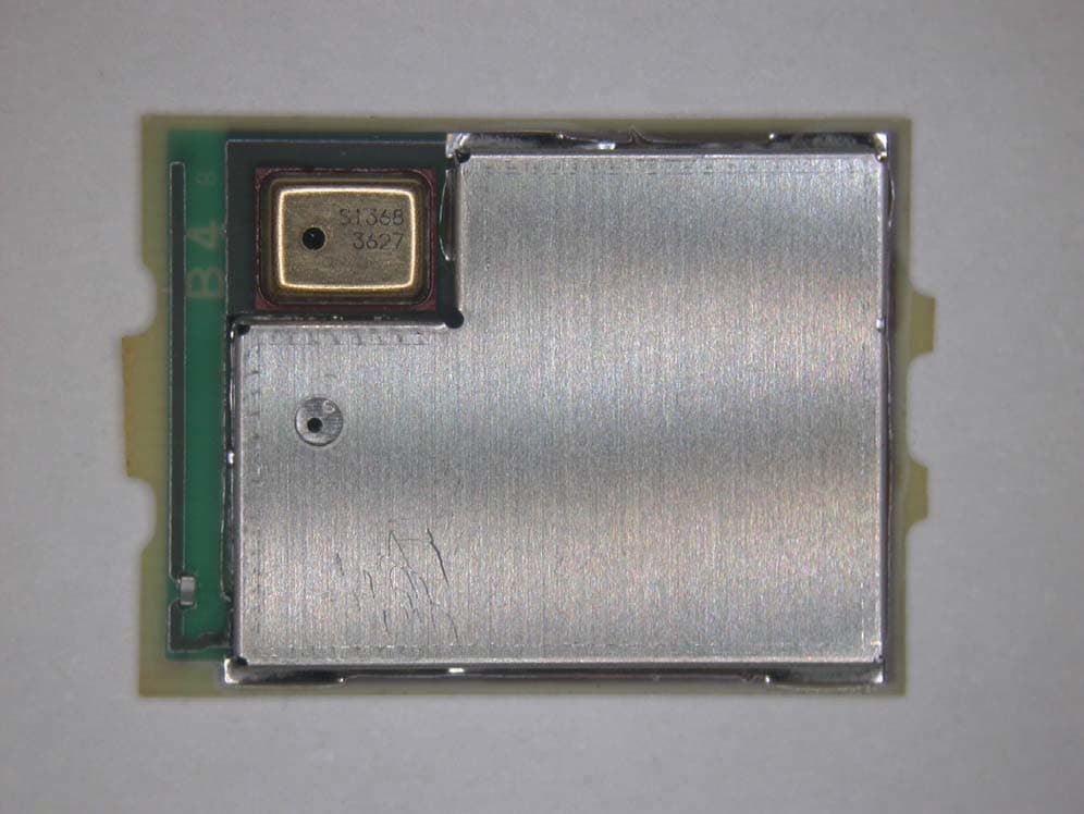
EJE-BT0004
Dec 06, 2015Ubiquitous-warecore module
Equipment Class
DTS - Digital Transmission System
EJE-WB0097
Nov 12, 2015FUJITSU STYLISTIC Q736
Equipment Class
DTS - Digital Transmission System