EJE-WB0012LIFEBOOK S SERIES WITH CAL2 11 ABG WLAN & BT
Fujitsu Client Computing Limited (FCCL)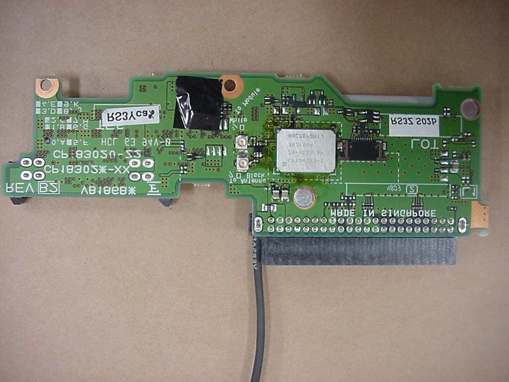
Click to zoom
Application Details
- Equipment Class
- DSS - Part 15 Spread Spectrum Transmitter
- Date of Grant
- Sep 23, 2004
- Application Purpose
- Original Equipment
- Date of Application
- Sep 23, 2004
- Equipment Note
- LIFEBOOK S SERIES WITH CAL2 11 ABG WLAN & BT
- Frequency Range
- 2402.00000000 - 2480.00000000
- Country
- Japan
Documents & Files
Document Text
Text extracted from the exhibit documents filed with the FCC. Open a document above to read the original.
Users Manual
Copyright Copyright Fujitsu Computer Systems Corporation has made every effort to ensure the accuracy and completeness of this document; however, as ongoing development efforts are continually improving the capabilities of our products, we cannot guarantee the accuracy of the contents of this document. We disclaim liability for errors, omissions, or future changes. Fujitsu, the Fujitsu logo, and LifeBook are registered trademarks of Fujitsu Limited. The following are registered trademarks of IBM Corporation: IBM, IBM PC AT, IBM PS/2. The following are registered trademarks of Microsoft Corporation: MS, MS-DOS, Windows. PCMCIA is a trademark of the Personal Computer Memory Card International Association. Earthlink is a registered trademark of EarthLink Network, Inc. Intel and Pentium are registered trademarks of Intel Corporation or its subsidiaries in the United States and other countries. The Bluetooth trademark is owned by Bluetooth SIG, Inc., USA. Adobe Acrobat Reader is a registered trademark of Adobe Systems, Inc. Netscape 7.0 is a registered trademark of Netscape Communications Corporation. PowerQuest and Drive Image are registered trademarks of PowerQuest Corporation. Norton AntiVirus is a registered trademark of Symantec Corporation. BayManager is a registered trademark of Softex, Inc. The DVD player found in some models of the LifeBook notebook incorporates copyright protection technology that is protected by method claims of certain U.S. patents and other intellectual property rights owned by Macrovision Corporation and other rights users. Use of this copyright protection technology must be authorized by Macrovision Corporation, and is intended for home and other limited viewing uses only unless authorized by Macrovision Corporation. Reverse engineering or disas- sembly is prohibited. Dolby Headphone manufactured under license from Dolby Laboratories. Dolby, Pro Logic, and the double-D symbol are trademarks of Dolby Laboratories. Copy- rights 1992-1999 Dolby Laboratories. All rights reserved. All other trademarks mentioned herein are the property of their respective owner s. © Copyright 2004 Fujitsu Computer Systems Corpora- tion. All rights reserved. No part of this publication may be copied, reproduced, or translated, without prior written consent of Fujitsu. No part of this publication may be stored or transmitted in any electronic form without the written consent of Fujitsu. B5FH-9991-01EN-00. Warning Handling the cord on this product will expose you to lead, a chemical known to the State of California to cause birth defects or other reproductive harm. Wash hands after handling. DECLARATION OF CONFORMITY according to FCC Part 15 Responsible Party Name:Fujitsu Computer Systems Corporation Address: 1250 E. Arques Avenue, M/S 122 Sunnyvale, CA 94085 Telephone:(408) 746-6000 Declares that product:Base Model Configurations: LifeBook S7010 notebook LifeBook S7010D notebook Complies with Part 15 of the FCC Rules. This device complies with Part 15 of the FCC rules. Operations are subject to the following two conditions: (1) This device must not be allowed to cause harmful interference, (2) This device must accept any interference received, including interference that may cause undesired operation. S Series.book Page 1 Thursday, February 12, 2004 4:15 PM LifeBook S7000 Notebook S Series.book Page 2 Thursday, February 12, 2004 4:15 PM Table of Contents Fujitsu LifeBook ® S7000 Notebook Table of Contents 1 PREFACE Preface About This Guide . . . . . . . . . . . . . . . . . . . . . . . . . 1 Fujitsu Contact Information . . . . . . . . . . . . . . . . . 1 Limited Warranty . . . . . . . . . . . . . . . . . . . . . . . . . 1 2 ABOUT YOUR LIFEBOOK Overview Unpacking . . . . . . . . . . . . . . . . . . . . . . . . . . . . . . 5 Locating the Controls and Connectors Top and Front Components . . . . . . . . . . . . . . . . . 6 Left-Side Panel Components . . . . . . . . . . . . . . . . 7 Right-Side Panel Components . . . . . . . . . . . . . . . 8 Back Panel Components . . . . . . . . . . . . . . . . . . . . 9 Bottom Components . . . . . . . . . . . . . . . . . . . . . 10 Status Indicator Panel Power Indicator . . . . . . . . . . . . . . . . . . . . . . . . . 11 AC Adapter Indicator . . . . . . . . . . . . . . . . . . . . . 11 Battery Level Indicators . . . . . . . . . . . . . . . . . . . 11 Battery Charging Indicators . . . . . . . . . . . . . . . . 12 DVD/CD-RW/CD-ROM Drive Access Indicator . . . . . . . . . . . . . . . . . . . . . . 12 Hard Drive or Removable Media Drive Access Indicator . . . . . . . . . . . . 12 PC Card Access Indicator . . . . . . . . . . . . . . . . . . 12 NumLk Indicator. . . . . . . . . . . . . . . . . . . . . . . . . 12 CapsLock Indicator . . . . . . . . . . . . . . . . . . . . . . . 12 ScrLk Indicator . . . . . . . . . . . . . . . . . . . . . . . . . . 12 Security Indicator . . . . . . . . . . . . . . . . . . . . . . . . 12 Keyboard Using the Keyboard . . . . . . . . . . . . . . . . . . . . . . 13 Numeric Keypad. . . . . . . . . . . . . . . . . . . . . . . . . 13 Windows Keys . . . . . . . . . . . . . . . . . . . . . . . . . . 13 Cursor Keys . . . . . . . . . . . . . . . . . . . . . . . . . . . . 13 Function Keys. . . . . . . . . . . . . . . . . . . . . . . . . . . 14 Touchpad Pointing Device Clicking . . . . . . . . . . . . . . . . . . . . . . . . . . . . . . . 15 Double-Clicking . . . . . . . . . . . . . . . . . . . . . . . . . 15 Dragging . . . . . . . . . . . . . . . . . . . . . . . . . . . . . . 16 Touchpad Control Adjustment . . . . . . . . . . . . . . 16 Scrolling . . . . . . . . . . . . . . . . . . . . . . . . . . . . . . . 16 Optional Quick Point Feature . . . . . . . . . . . . . . . 16 Volume Control Controlling the Volume . . . . . . . . . . . . . . . . . . . 17 Flexible Bay Devices Removing and Installing Modular Devices . . . . . 18 LifeBook Security/Application Panel Setting up Your LifeBook Security Panel . . . . . . . 20 Passwords . . . . . . . . . . . …
Text truncated - open the document above for the full version.
Users Manual
53 5 Troubleshooting S Series.book Page 53 Thursday, February 12, 2004 4:15 PM 54 LifeBook S7000 Notebook S Series.book Page 54 Thursday, February 12, 2004 4:15 PM 55 Troubleshooting Troubleshooting Your Fujitsu LifeBook notebook is sturdy and subject to few problems in the field. However, you may encounter simple setup or operating problems that you can solve on the spot, or problems with peripheral devices, that you can solve by replacing the device. The information in this section helps you isolate and resolve some of these straightforward problems and identify failures that require service. IDENTIFYING THE PROBLEM If you encounter a problem, go through the following procedure before pursuing complex troubleshooting: 1. Turn off your LifeBook notebook. 2. Make sure the AC adapter is plugged into your note- book and to an active AC power source. 3. Make sure that any card installed in the PC Card slot is seated properly. You can also remove the card from the slot, thus eliminating it as a possible cause of failure. 4. Make sure that any devices connected to the external connectors are plugged in properly. You can also disconnect such devices, thus eliminating them as possible causes of failure. 5. Turn on your notebook. Make sure it has been off at least 10 seconds before you turn it back on. 6. Go through the boot sequence. 7. If the problem has not been resolved, refer to the Troubleshooting Table, that follows, for more detailed troubleshooting information. 8. If you have tried the solutions suggested in the Trou- bleshooting Table without success, contact your support representative: Toll free: 1-800-8Fujitsu (1-800-838-5487) E-mail: [email protected] Web site: us.fujitsu.com/computers. Before you place the call, you should have the following information ready so that the customer support represen- tative can provide you with the fastest possible solution: ■ Product name ■ Product configuration number ■ Product serial number ■ Purchase date ■ Conditions under which the problem occurred ■ Any error messages that have occurred ■ Hardware configuration ■ Type of device connected, if any See the Configuration Label on the bottom of your notebook for configuration and serial numbers. (See figure 2-8 on page 10 for location) SPECIFIC PROBLEMS Using the Troubleshooting Table When you have problems with your LifeBook notebook, try to find the symptoms under the Problem column of the troubleshooting table for the feature giving you difficulty. You will find a description of common causes for that symptom under the column Possible Cause and what, if anything, you can do to correct the condition under Possible Solutions. All possible causes or solutions may not apply to your notebook. If you keep notes about what you have tried, your support representative may be able to help you more quickly by giving additional suggestions over the phone. S Series.book Page 55 Thursday, February 12, 2004 4:15 PM 56 LifeBook S7000 Notebook TR O U B L E S H O O T I N G TA B L E ProblemPage Audio Problems . . . . . . . . . . . . . . . . . . . . . . . . . . page 56 DVD/CD-ROM Drive Problems. . . . . . . . . . . . . page 56 Port Replicator Problems. . . . . . . . . . . . . . . . . . . page 57 Floppy Disk Drive Problems . . . . . . . . . . . . . . . . page 57 Hard Drive Problems . . . . . . . . . . . . . . . . . . . . . . page 57 Keyboard or Mouse Problems . . . . . . . . . . . . . . . page 57 Memory Problems . . . . . . . . . . . . . . . . . . . . . . . . page 58 ProblemPage Modem Problems. . . . . . . . . . . . . . . . . . . . . . . . . page 58 Parallel, Serial and USB Device Problems . . . . . page 58 PC Card Problems . . . . . . . . . . . . . . . . . . . . . . . . page 59 Power Failures . . . . . . . . . . . . . . . . . . . . . . . . . . . page 59 Shutdown and Startup Problems . . . . . . . . . . . . page 61 Video Problems . . . . . . . . . . . . . . . . . . . . . . . . . . page 61 Miscellaneous Problems . . . . . . . . . . . . . . . . . . . page 63 ProblemPossible CausePossible Solutions Audio Problems There is no sound coming from the built-in speakers. The volume is turned too low.Adjust the volume control on your notebook. The software volume control is set too low. Adjust the sound volume control settings in your software, operating system and applications. Headphones are plugged into your notebook. Plugging in headphones disables the built-in speakers, remove the headphones. BIOS audio settings are incorrect. Set the BIOS setup utility to the default values within the Multimedia Device Configuration menu. (See BIOS Setup Utility on page 29 for more information) Software driver is not configured correctly. Refer to your application and operating system documentation for help. The speakers have been muted using the Volume icon in the system tray. Click on the Volume icon in the tool tray on the bottom right of the screen. (It looks like a speaker). If the Mute box is checked, click on it to uncheck it. DVD/CD-RW/CD-ROM Drive Problems LifeBook notebook fails to recognize DVD/CD-RW/ CD-ROM’s. Protective sheet is still in the DVD/CD-RW/CD-ROM drive tray. Replace DVD/CD-RW/CD-ROM in tray. DVD/CD-RW/CD-ROM is not pushed down onto raised center circle of the drive. Open DVD/CD-RW/CD-ROM tray and re-install DVD/CD-RW/CD-ROM properly. DVD/CD-RW/CD-ROM tray is not latched shut. Push on the front of the DVD/CD-RW/CD-ROM tray until it latches. Incorrect DVD Player or no DVD Player software is installed. Install DVD Player software. (See “Media Player Software” on page 39 for more information.) Wrong drive designator was used for DVD/CD-RW/CD- ROM in the application. Verify the drive designator used by the application is the same as the one used by the operating system. When the operating system is booted from a DVD/ CD, drive designations are automatically adjusted. Windows DVD/CD-RW/CD- ROM auto insertion function is disabled. Start the DVD/CD-RW/CD-ROM from the desktop or application software or re-enable th…
Text truncated - open the document above for the full version.
Block Diagram
UGXZ5-#### Block Diagram DAC LNA Demodulator ADC PA Clock generation Physical layer hardware engine DSP Burst mode controller Memory management unit RAM Memory mapped control / status USB Syncronous Serial Interface UART Audio PCM Interface Extended Memory Driver 18 16 Programmable PIO RISC micro- controller Interrupt controller Event timer RF Synthesizer /N/N+1 Fref Tune -45 +45 AUX DAC VDD_MEM VDD_PADS VDD_RADIO VDD_VCO VDD_ANA VDD_CORE VSS_MEM VSS_PADS VSS_PIO VSS_RADIO VSS_VCO VSS_ANA VSS_CORE X'tal (16MHz) 1.8V Voltage Regrlator Baseband and Logic Microcontroller RF Synthesizer RF Transmitter RF Receiver IQ Demod. IQ mod. RSSI 8Mb Flash ROM BlueCore TM 2-EXT Loop Filter UART_RxD (#19) UART_TxD (#20) UART_CTS (#21) UART_RTS (#22) PCM_CLK (#14) PCM_OUT (#15) PCM_SYNC (#16) PCM_IN (#17) SPI_CLK (TP) SPI_MISO (TP) SPI_MOSI (TP) SPI_CSB (TP) USB_D+ (#23) USB_D- (#24) SPI_CSB (#10) USB_WAKE (#9) SPI_CLK (#7) USB_DETACH (#8) SPI_CSB PIO[3] SPI_CLK PIO[5] UART_RX UART_TX UART_CTS UART_RTS PCM_CLK PCM_OUT PCM_SYNC PCM_IN SPI_CLK SPI_MISO SPI_MOSI SPI_CSB USB_D+ USB_D- SPI_MOSI SPI_MISO PIO[8] PIO[9] PIO[10] PIO[11] SPI_MOSI (#12) SPI_MISO (#11) Balun PA PIO[1]/TXEN AUX_DAC PIO[0]/RXEN ANT-SW RF-BPF RF IN/OUT (#5) VCC (#2) VDD (#3) RESET GND (#1, 6, 13, 18) RF front-end RESET (#4) 1.5MHz TX:2402MHz-2480MHz RX:2400.5MHz-2478.5MHz 2402MHz-2480MHz 2402MHz-2480MHz 1.5MHz ALPS PROPRIETARY INFORMATION CONFIDENTIAL REQUESTED Copyright (c) 2004 ALPS Electric Co., Ltd.
External Photos
FCC ID: EJE-WB0012 (IC: 337J-WB0012) Report No. M040765_Cert_Onion2_BT_Cal2_11abg EMC Technologies Pty Ltd – 57 Assembly Drive, Tullamarine VIC 3043 Australia www.emctech.com.au EMC Technologies Report Number: M040765_Cert_Onion2_BT_Cal2_11abg APPENDIX B1 – Test Sample Photographs (external) FCC ID: EJE-WB0012 (IC: 337J-WB0012) Report No. M040765_Cert_Onion2_BT_Cal2_11abg EMC Technologies Pty Ltd – 57 Assembly Drive, Tullamarine VIC 3043 Australia www.emctech.com.au Test Sample – Bluetooth, Model UGXZ5-102A FCC ID: EJE-WB0012 (IC: 337J-WB0012) Report No. M040765_Cert_Onion2_BT_Cal2_11abg EMC Technologies Pty Ltd – 57 Assembly Drive, Tullamarine VIC 3043 Australia www.emctech.com.au Test Sample – LifeBook S Series (Onion2)
ID Label/Location Info
FCC ID: EJE-WB0012 (IC: 337J-WB0012) Report No. M040765_Cert_Onion2_BT_Cal2_11abg EMC Technologies Pty Ltd – 57 Assembly Drive, Tullamarine VIC 3043 Australia www.emctech.com.au EMC Technologies Report Number: M040765_Cert_Onion2_BT_Cal2_11abg APPENDIX G – FCC Labelling
Internal Photos
FCC ID: EJE-WB0012 (IC: 337J-WB0012) Report No. M040765_Cert_Onion2_BT_calexico2_11abg EMC Technologies Pty Ltd – 57 Assembly Drive, Tullamarine VIC 3043 Australia www.emctech.com.au EMC Technologies Report Number: M040765_Cert_Onion2_BT_Calexico2_11abg APPENDIX B4 – Test Sample Photographs (internal) FCC ID: EJE-WB0012 (IC: 337J-WB0012) Report No. M040765_Cert_Onion2_BT_Calexico2_11abg EMC Technologies Pty Ltd – 57 Assembly Drive, Tullamarine VIC 3043 Australia www.emctech.com.au Test Sample Bluetooth – UGXZ5-102A Exploded view – Shielding removed FCC ID: EJE-WB0012 (IC: 337J-WB0012) Report No. M040765_Cert_Onion2_BT_Calexico2_11abg EMC Technologies Pty Ltd – 57 Assembly Drive, Tullamarine VIC 3043 Australia www.emctech.com.au Host PC - LifeBook S Series, Model S7010, S7011 (Onion2)
Operational Description
1 Bluetooth TM Transceiver Module, UGXZ5 Theory of Operation Bluetooth is an open standard developed by four OEM’s (Ericsson, Nokia, IBM, and Toshiba) and one semiconductor company (Intel). The standard aims to define a globally accepted short distance (10m/30ft) radio communication protocol using a part of the radio frequency that is unlicensed (i.e. free to use) in most parts of the world. Bluetooth’s key characteristic is that enabled devices can detect and communicate with other enabled devices within range – all without conscious user intervention. The Bluetooth Transceiver module, UGXZ5 is a module of SMD (Surface Mounted Device) type. It contains an USB interface that is compliant with Universal Serial Bus Specification. It also contains a radio transmitter and receiver that are compliant with Bluetooth Spesification published by the Bluetooth Speci al Interest Group. The combination of the radio and associated Bluetooth software stack, and application software provides a convenient way for the host platform to wirelessly interact with various devices such as mobile ph ones, printers, etc. The radio part of the UGXZ5 is specified in the Bluetooth open standard. It operates in the frequency band of 2402 to 2480 MHz at a radiated power level of 0.011 watt maximum. It radiates using Gaussian Frequency shift keying and uses frequency hopping sprea d spectrum on 79 equally spaced channels. All channels are 1 MHz apart and hop through the channels using a pseudo- random hopp ing sequenc e. The device hops from channel to channel at a rate of 16 00 hops per second. The radio is completely controlled by the associated software stack and application program. The stack controls the hopping sequence, and protocols for establishing a connection with other Bluetooth devices in the near vicinity. Then, the radio has the function of Adaptive Frequency Hopping (AFH) that is used to improve the performance of physical links in the presence of interference as well as reducing the interference caused by physical links on other devices in the ISM band. AFH shall only be used during the connection state. 1. Derivation of the pseud or andom hop ping sequence. Hopping sequence selection for a system is controlled by the master unit within a specific system. The sequence is selected by a combination of address codes and master unit system clock. The pseudo-random sequence is generated in a nine-stage shift register whose 5 th and 9 th stage outputs are added in a modulo-two addition stage with the result fed back to the input of the first stage. This produces a pseudo-random sequence length of 31 bits for page and inquiry modes and provides for transition to a 511 bits pseudorandom sequence length for data mode of operation. The following are two examples of possible 79 channel hop ping sequences with channels identif ied as 1 through 79. The channel numbering scheme starts with channel 2 at 2402 MHz with the 79 th channel then appearing at 2480 MHz as channel 80. 2 Sequence a: 2,17,68,55,4,77,56,27,70,80,22,33,57,34,29,79,44,50,3,71,66,36,78,20,67,30,24,11,37,69, 23,7,41,38,63,14,31,59,40,13,6,25,65,15,61,73,58,47,19,28,54,76,74,48,52,75,5,42,64,72, 62,51,60,18,45,53,16,39,46,32,49,43,8,21,9,12,10,26,35 Sequence b: 50,6,41,57,64,14,42,33,79,3,20,38,56,69,75,21,80,23,31,40,45,68,32,28,4,15,34,59,71,61, 70,5,72,13,48,70,39,54,78,7,77,62,30,2,8,55,10,63,12,16,37,11,43,66,25,51,58,74,17,47, 9,29,65,19,53,18,52,36,27,26,44,22,49,24,35,60,73,76,67 2. Use of each frequency equally on average. The FHS (frequency hop selection) packet is transmitted by a sending unit. It contains UAP (upper address part)/LAP (lower address part) as well as clock information which is updated before retransmission in the inquiry state. When in hybrid substate, the UAP/LAP is used together with the clock to select the sequence. The output from the selection box constitutes a pseudo-random sequence covering 79 hops for US operation. For inquiry mode, the selection scheme chooses a segment of 32 hop frequencies from the 79 hops spanning about 64 MHz and visits these hops once in a random order. Next, a different 32-hop segment is chosen, etc. Refer to “Baseband Specification”, clause 2.6 hop selection of the Bluetooth specification V1.2 for a more through explanation of the hopping structure. 3. Receiver matching bandwidth and synchronization. The receiver bandwidth is 1 MHz in the data mode. During connection establishment, the master identity and clock are transferred to the slave unit so it can synchronize to the channel. The master clock in a slave unit is obtained by adding an offset to the internal clock of the slave. Also see above item 1 for details on the master clock and pseudo-random hopping channel selection. 4. Antenna. RF energy is radiated from the module through an external antenna that is specified in the “Declaration concerning Antenna Specification”. 5. More information. The current Bluetooth specification version 1.2 is available to anyone at no cost from the Bluetooth SIG, Inc. website at http://www.bluetooth.com/ .
RF Exposure Info
FCC ID: 337J-WB0012 (IC: 337J-WB0012) Report No. M040765_Cert_Onion2_BT_Cal2_11abg This document must not be copied or reproduced, except in full without the written permission of the Manager, EMC Technologies Pty Ltd. The certificate on page 3 may be reproduced in full. www.emctech.com.au RADIO FREQUENCY EXPOSURE (HAZARD) INFORMATION Testing was performed in accordance with the requirements of FCC Part 15.247(b)(5) Spread spectrum transmitters operating in the 2400 - 2483.5 MHz bands are required to be operated in a manner that ensures that the public is not exposed to RF energy levels in accordance with CFR 47, Section 1.1307(b)(1). In accordance with this section and also section 2.1091 this device has been defined as a mobile device whereby a distance of 20 cm normally can be maintained between the user and the device. In accordance with Section 1.1310, the Maximum Permissible Exposure (MPE) limit for the General Population/Uncontrolled Exposure of 1.0 has been applied, i.e 1mW/cm 2 . Friis transmission formula: Pd = (P*G) / (4*π*r 2 ) where: Pd = power density (mW/cm 2 ) P = power input to the antenna (mW) G = antenna gain (numeric) r = distance to the center of radiation of the antenna (cm) The result was extracted from section 3.0 of EMC Technologies Report No: M040765_Cert_Onion2_BT_Cal2_11abg (Bluetooth): Maximum peak output power = 10.41dBm = 11.0 mW Antenna (Monopole Ceramic Chip) gain (typical) = 2.08 dBi = 1.61 numeric Prediction distance = 20 cm Prediction frequency = 2402 MHz MPE limit for uncontrolled exposure at prediction frequency = 1 mW/cm 2 Therefore, the power density at prediction frequency (Pd) = 0.0035mW/cm 2 The result was extracted from section 3.0 of EMC Technologies Report No: M040765_Cert_Onion2_Cal2_11abg_DTS_BT (WLAN Module): Maximum peak output power = 19.2dBm = 83.2mW Antenna (Monopole Ceramic Chip) gain (typical) = 1.28 dBi = 1.34 numeric Prediction distance = 20 cm Prediction frequency = 2437 MHz MPE limit for uncontrolled exposure at prediction frequency = 1 mW/cm 2 Therefore, the power density at prediction frequency (Pd) = 0.0222 mW/cm 2 The total power density (TPd) for WLAN and Bluetooth transmitters continuously operated: TPd = 0.0222 (WLAN) + 0.0035 (Bluetooth) = 0.026mW/cm 2 Calculations show that this device with described antenna does meet the MPE requirements for portable devices falling below the 20 cm clearance required. Results: Complies
Schematics
FCC ID: EJE-WB0012 (IC: 337J-WB0012) Report No. M040765_Cert_Onion2_BT_Cal2_11abg EMC Technologies Pty Ltd – 57 Assembly Drive, Tullamarine VIC 3043 Australia www.emctech.com.au EMC Technologies Report Number: M040765_Cert_Onion2_BT_Cal2_11abg APPENDIX E – Schematic 1 1 2 2 3 3 4 4 5 5 6 6 7 7 8 8 9 9 AA BB CC DD EE FF GG C1CP209735-X1 Soriel TP/BT Board 14 2004.05.25 FUJITSU LTD. CUST. APPR.CHECKDESIGN REV.DATEDESIGNAPPR.DESCRIPTIONSHEET DRAW. TITLE DATE CHECK NO. 1 1 2 2 3 3 4 4 5 5 6 6 7 7 8 8 9 9 AA BB CC DD EE FF GG 1A C1CP209735-X1 Soriel TP/BT Board 24 2004.05.25 FUJITSU LTD. CUST. APPR.CHECKDESIGN REV.DATEDESIGNAPPR.DESCRIPTIONSHEET DRAW. TITLE DATE CHECK NO. LPC_FRAME#3 LPC_AD33 LPC_AD23 LPC_AD13 BLUE_DETACH4 BLUE_RST#4 BTON4 ANT_BTEN#4 CLK_33_TPM3 SERIRQ3 LPC_AD03 USB_P5-4 USB_P5+4 PCI_RST#3 PCI_CLKRUN#3 BLUE_RI#4 BLUE_EXIST#4 PWR_3VMAIN GND1 PWR_3VSTD CN1 BT CN (26) Straight CA98010-5936 1 1 2 2 3 3 4 4 5 5 6 6 7 7 8 8 9 9 10 10 11 11 12 12 13 13 14 14 15 15 16 16 17 17 18 18 19 19 20 20 21 21 22 22 23 23 24 24 25 25 26 26 1 1 2 2 3 3 4 4 5 5 6 6 7 7 8 8 9 9 AA BB CC DD EE FF GG TPM Configuration TPM_BADDR HighLow 4E/4Fh2E/2Fh TPM_BACCESSPhysical Presence Physical Presence ONOFF C1CP209735-X1 Soriel TP/BT Board 34 2004.05.25 FUJITSU LTD. CUST. APPR.CHECKDESIGN REV.DATEDESIGNAPPR.DESCRIPTIONSHEET DRAW. TITLE DATE CHECK NO. TPM_BADDR TPM_PACCESS TPM_PACCESS TPM_BADDR LPC_AD32 LPC_AD22 LPC_AD12 LPC_AD02CLK_33_TPM2 PCI_CLKRUN#2 SERIRQ2 PCI_RST#2 LPC_FRAME#2 GND1 PWR_3VMAIN GND1 GND1 PWR_3VMAIN PWR_3VMAIN R2 4.7K 1/16W 5% 2 1 TL2 TL1 R4 4.7K 1/16W 5% TPM 2 1 M1 SLD9630TT_1.1 CA46120-0010 LAD0 2 LAD1 3 LAD2 6 LAD3 7 LCLK 8 LFRAME# 13 LRESET# 27 LPCPD# 26 SERIRQ 12 BADDR 20 RSVD 9 VDDC 19 VDD 5 VDD 11 VDD 25 GND 4 GND 10 GND 18 GND 24 PENABLE 22 PACCESS 21 TESTIO 16 TESTEN 17 CLKRUN# 23 NC1 1 NC2 14 NC3 15 NC4 28 R3 0 1/16W TPM None 1 2 C4 0.1uF 16V FZ 2 1 R1 4.7K 1/16W 5% 2 1 C1 0.1uF 16V FZ 2 1 C2 0.1uF 16V FZ 2 1 C3 0.1uF 16V FZ 2 1 1 1 2 2 3 3 4 4 5 5 6 6 7 7 8 8 9 9 AA BB CC DD EE FF GG GND1 GND1 GND1 1A 3.3V 1A C1CP209735-X1 Soriel TP/BT Board 44 2004.05.25 FUJITSU LTD. CUST. APPR.CHECKDESIGN REV.DATEDESIGNAPPR.DESCRIPTIONSHEET DRAW. TITLE DATE CHECK NO. BTDETACH BLUERI BTRST# RF_BT USB_P5N USB_P5PPWR_BT RF_SW_OUT2RF_BT RF_SW_INRF_ANT RF_SW_OUT1RF_WLAN ANT_BTEN ANT_WEN BTRST# BLUERI BTDETACH USB_P5+2 USB_P5-2 ANT_BTEN#2 BLUE_RST#2 BLUE_DETACH2 BLUE_RI#2 BTON2 BLUE_EXIST#2 PWR_BT GND1 GND1 PWR_3VSTD GND1 GND1 PWR_BT GND1GND1GND1 PWR_BT PWR_BT GND1 PWR_BT GND1 PWR_3VSTD GND1 PWR_BT GND1 M2 UGXZ BT GND 1 VCC 2 VDD 3 RESET 4 RF IN/OUT 5 GND 6 VBUS_IN 7 USB_DETACH 8 USB_WAKE 9 PORT1 10 PORT2 11 PORT3 12 GND 13 PCM_CLK 14 PCM_OUT 15 PCM_SYNC 16 PCM_IN 17 GND 18 UART_RxD 19 UART_TxD 20 UART_CTS 21 UART_RTS 22 USB_D+ 23 USB_D- 24 C9 10uF 6.3V 2012 RM BT 1 2 C8 0.1uF 16V FZ BT 1 2 C7 0.1uF 16V FZ BT 1 2 R7 10K 1/16W 5% None BT 1 2 C11 10pF 25V BT 12 C10 10pF 25V BT 12 C12 10pF 25V BT 12 R8 10K 1/16W 5% 1 2 CN2 ANT BT 1 2 3 CN3 W-LAN BT 1 2 3 M4 SPM3501 BT CTL2 6 CTL1 4 IN 5 OUT2 3 GND 2 OUT1 1 Q5 2SK3019 BT 1 3 2 C13 0.1uF 16V FZ BT 2 1 C14 0.1uF 16V FZ BT 2 1 Q4 DTC144EEBT 1 2 3 R5 4.7K 1/16W 5% BT 2 1 Q1 DTC143TEA BT 1 2 3 C5 0.1uF 16V FZ 2 1 C6 0.01uF 16V RK 2 1 D1 RB521S-30 BT 21 R11 4.7K 1/16W 5% BT 1 2 Q2 DTC144EEBT 1 2 3 Q3 DTC144EEBT 1 2 3 TP1 PWR_BT R9 470K 1/16W 5% BT 2 1 C15 0.1uF 16V FZ BT 1 2 Q6 SI2305DS BT 1 32 R12 47K 1/16W 5% BT 1 2 Q7 DTC144EEBT 1 2 3 R60 1/16W None 12 M3 R3112Q271C-TR-FA (RoHS) CA46510-0082 BT VDD 1 GND 2 CD 3 OUT 4 R10 0 1/16W BT 2 1
Test Report
FCC ID: 337J-WB0012 (IC: 337J-WB0012) Report No. M040765_Cert_Onion2_BT_Cal2_11abg This document must not be copied or reproduced, except in full without the written permission of the Manager, EMC Technologies Pty Ltd. The certificate on page 3 may be reproduced in full. www.emctech.com.au APPENDIX A MEASUREMENT INSTRUMENTATION DETAILS EQUIPMENT TYPE MAKE/MODEL SERIAL NUMBER LAST CAL. DD/MM/YY DUE DATE DD/MM/YY CAL. INTERVAL EMI RECEIVER HP 8574B System Components 26/09/03 26/09/04 1 YEAR *2 EMI RECEIVER HP 8546A, Sn: 3549A00290 13/02/04 13/02/05 1 YEAR *2 EMI RECEIVER Rohde & Schwarz, Model ESIB40 SN 1088 7490, 20 Hz – 40 GHz 20/07/04 20/07/05 1 YEAR *3 EMI RECEIVER Rohde & Schwarz, Model FSET22 SN 1080 3508, 100 Hz – 22 GHz 31/10/03 31/10/04 1 YEAR *3 RF PRE-SELECTOR Rohde & Schwarz, Model FSET-Z22 SN 1070 2009, 100 Hz – 22 GHz 31/10/03 31/10/04 1 YEAR *3 ANTENNAS EMCO 93110B BICONICAL 20/08/03 20/08/04 1 YEAR *1 20 - 300 MHz Sn. 9804-3092 EMCO 93146A LOG PERIODIC 19/07/04 19/07/05 1 YEAR *1 200 -1000MHz Sn. 5033 EMCO 3115 DOUBLE RIDGED HORN 1 - 18 GHz Sn: 8908-3282 29/01/03 29/01/06 3 YEAR *1 EMCO 3116 Double Ridged Guide Horn -------- -------- *4 18 – 40 GHz Sn 2276 LISN EMCO 3825/2 50ohm / 50 microH 31/03/04 31/03/05 1 YEAR *1 0.009 – 30MHz Sn.9607-2567 Note *1. In-house calibration. Refer to Quality Manual. Note *2. NATA calibration by Agilent Technologies (Aust) Pty Ltd Note *3. NATA calibration by Rohde & Schwarz Note *4. Manufacturer’s calibration TEST SITES Shielded Room Test Laboratory Melbourne 11m x 8m x 4m Chamber-semi-anechoic 8.8m x 5.8m x 3.1m Test Chamber 3.4m x 6.1m x 2.5m Test Chamber 3.4m x 7.3m x 7.5m Test Chamber Feb 03 N/A N/A N/A Feb 04 N/A N/A N/A 1 Year *1 N/A N/A N/A Open Area Test Site Melbourne 3/10 Metre site. 1-4 metre antenna mast. 1.2 metre/400 kg Turntable. (Situated at Lerderderg Gorge, near Bacchus Marsh, Victoria) 11/02/04 11/02/05 1 Year *1 Note *1. In-house calibration. Refer to Quality Manual.
Test Report
1 Part A RADIO SPECIFICATION Core System Package [Controller volume] CONTENTS 1 Scope ..................................................................................................2 2 Frequency Bands and Channel Arrangement .................................3 3 Transmitter Characteristics...............................................................4 3.1 Modulation Characteristics...............................................................5 3.2 Spurious Emissions..........................................................................6 3.2.1 In-band spurious emission ............................................ ...............6 3.3 Radio Frequency Tolerance .............................................................7 4 Receiver Characteristics ...................................................................8 4.1 Actual Sensitivity Level ....................................................................8 4.2 Interference Performance ................................................................8 4.3 Out-of-Band Blocking........................................................................9 4.4 Intermodulation Characteristics.........................................................9 4.5 Maximum Usable Level...................................................................10 4.6 Receiver Signal Strength Indicator..................................................10 4.7 Reference Signal Definition.............................................................10 5 Appendix A .........................................................................................11 6 Appendix B .........................................................................................13 2 …
Text truncated - open the document above for the full version.
Contact Information
Applicant
Mr. Tsuyoshi Uchihara(Engineer)
Test Firm
EMC Technologies Pty. Ltd.Michael Evans
Technical Specifications
| # | Rule Parts | Frequency Range | Power Output |
|---|---|---|---|
| 1 | 15C | 2.40 GHz - 2.48 GHz | 10.00 mW |
Other Applications from Fujitsu Client Computing Limited (FCCL)
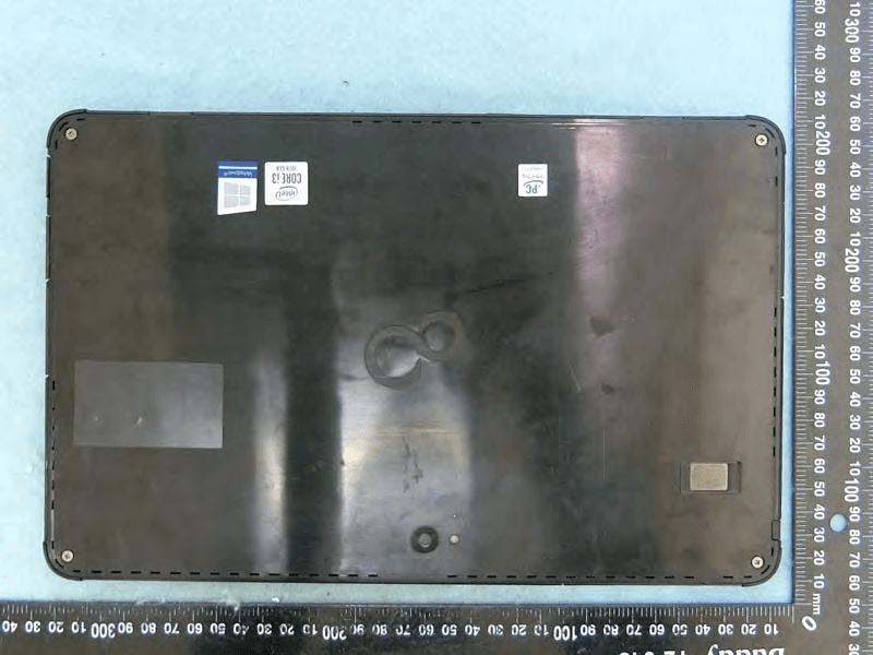
EJE-KST001
May 13, 2020Tablet Computer
Equipment Class
DXX - Part 15 Low Power Communication Device Transmitter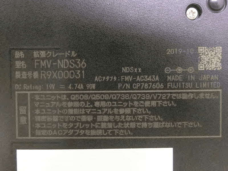
EJE-KSC001
May 13, 2020Port Replicator
Equipment Class
DXX - Part 15 Low Power Communication Device Transmitter
EJE-WB0099
Jan 27, 2016STYLISTIC Q series
Equipment Class
DSS - Part 15 Spread Spectrum Transmitter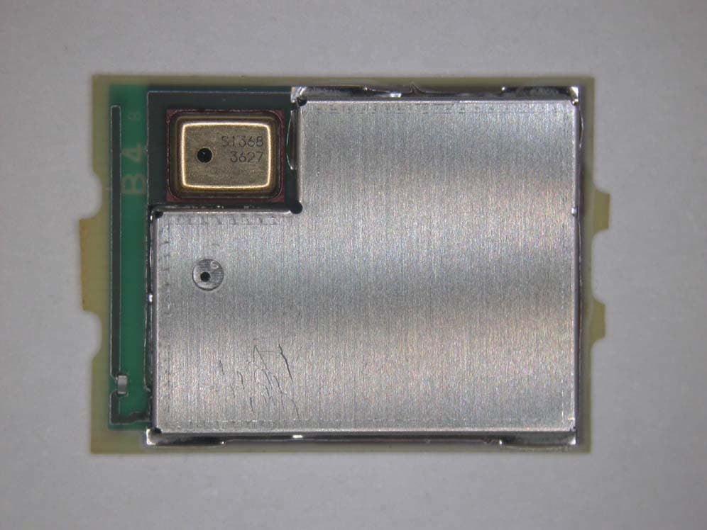
EJE-BT0004
Dec 06, 2015Ubiquitous-warecore module
Equipment Class
DTS - Digital Transmission System
EJE-WB0097
Nov 12, 2015FUJITSU STYLISTIC Q736
Equipment Class
DTS - Digital Transmission System