EJE-WB0013Stylistic ST Series w/ WLAN Calexico2 (11abg) & BT
Fujitsu Client Computing Limited (FCCL)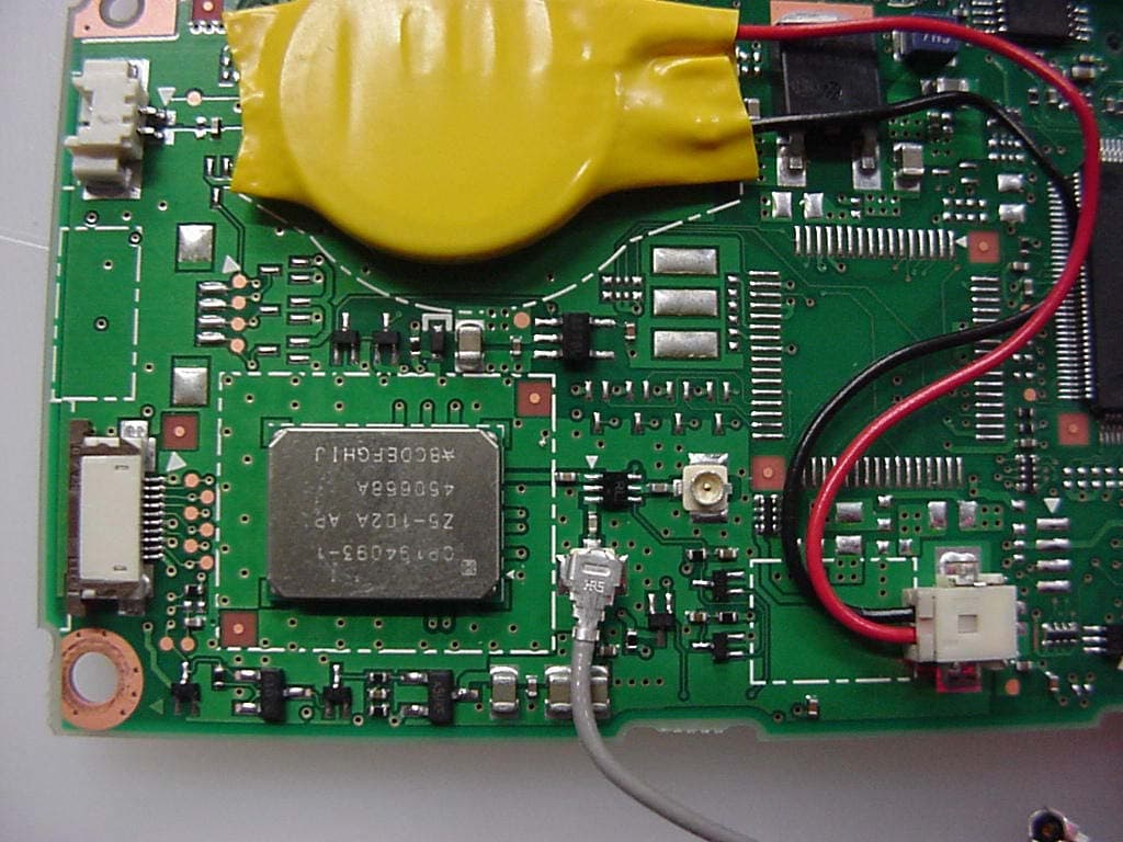
Click to zoom
Application Details
- Equipment Class
- DSS - Part 15 Spread Spectrum Transmitter
- Date of Grant
- Nov 18, 2004
- Application Purpose
- Original Equipment
- Date of Application
- Sep 26, 2004
- Equipment Note
- Stylistic ST Series w/ WLAN Calexico2 (11abg) & BT
- Frequency Range
- 2402.00000000 - 2480.00000000
- Country
- Japan
Documents & Files
Document Text
Text extracted from the exhibit documents filed with the FCC. Open a document above to read the original.
Users Manual
Copyright Fujitsu Computer Systems Corporation has made every effort to ensure the accuracy and completeness of this document. Because ongoing development efforts are made to continually improve the capabilities of our prod- ucts, however, the data contained herein represents Fujitsu design objectives and is provided for comparative purposes; actual results may vary based on a variety of factors. This product data does not constitute a warranty. Specifications are subject to change without knowledge. Fujitsu and the Fujitsu logo are registered trademarks of Fujitsu Limited; Stylistic is a registered trademark of Fujitsu Computer Systems Corporation. Microsoft and Windows are registered trademarks of Microsoft Corporation. PCMCIA and CardBus are registered trademarks of the Personal Computer Memory Card International Associa- tion. Intel, Pentium, and SpeedStep are registered trademarks of Intel Corporation. Atheros is a registered trademark of Atheros Communi- cations, Inc. PowerQuest and Drive Image are registered trademarks of PowerQuest Corp. Kensington and MicroSaver are registered trademarks of the Kensington Technology Group. SanDisk and the SanDisk logo are registered trademarks of SanDisk Corporation. Memory Stick is a registered trademark of Sony Corpora- tion and/or its affiliates Wi-Fi is a trademark of the Wireless Ethernet Compati- bility Alliance (WECA). All other products are trademarks or registered trade- marks of their respective companies. Copyright 2004-Fujitsu Computer Systems Corporation. All rights reserved. No part of this publication may be copied, reproduced, or translated, without the prior written consent of Fujitsu Computer Systems Corpora- tion. No part of this publication may be stored or trans- mitted in any electronic form without the prior consent of Fujitsu Computer Systems Corporation. B6FH-0561-02EN-00 Note:For more detailed information about the FCC rules and their applicability to the Stylistic ST5000 Series Tablet PC, refer to Chapter 5 of this document. Warning Handling the cord on this product will expose you to lead, a chemical known to the State of California to cause birth defects or other reproductive harm. Wash hands after handling. DECLARATION OF CONFORMITY according to FCC Part 15 Responsible Party Name:Fujitsu Computer Systems Corporation Address:1250 E. Arques Avenue, MS 122 Sunnyvale, CA 954085 Telephone:408-746-6000 Declares that product:Model Series: Stylistic® ST5000 Tablet PC Complies with Part 15 of the FCC Rules This device complies with Part 15 of the FCC rules. Operation is subject to the following two conditions: (1) This device may not cause harmful interference, and, (2) This device must accept any interference received, including interference that may cause undesired operation. Stylistic ST5000 Series Tablet PC - User’s Guide Table of Contents Table of Contents PREFACE About This Guide . . . . . . . . . . . . . . . . . . . . . . . . . v Fujitsu Contact Information . . . . . . . . . . . . . . . . . v Warranty Information . . . . . . . . . . . . . . . . . . . . . v 1 GETTING STARTED WITH YOUR TABLET PC Getting Started In-box Items for the Stylistic ST5000 Series Tablet PC . . . . . . . . . . . . . . . . . . 1 Optional Accessories . . . . . . . . . . . . . . . . . . . . . . 2 Stylistic Tablet PC Features. . . . . . . . . . . . . . . . . . 3 Status Display. . . . . . . . . . . . . . . . . . . . . . . . . . . . 8 Application Buttons . . . . . . . . . . . . . . . . . . . . . . 10 Navigation Buttons. . . . . . . . . . . . . . . . . . . . . . . 12 Tertiary Functions of Application and Navigation Buttons. . . . . . . . . . . . . . . . . . 13 Security Functions of Application Buttons. . . . . . 14 Setting up the Security Panel . . . . . . . . . . . . . . . 14 Passwords . . . . . . . . . . . . . . . . . . . . . . . . . . . . . 14 Using Your Security Panel . . . . . . . . . . . . . . . . . 15 Precautions . . . . . . . . . . . . . . . . . . . . . . . . . . . . 15 Uninstalling the Security Panel Application . . . . . 15 Connectors and Peripheral Interfaces . . . . . . . . . 17 2 USING YOUR TABLET PC Using the Stylistic ST5000 Series Tablet PC System States . . . . . . . . . . . . . . . . . . . . . . . . . . . 21 Powering Up the Tablet PC . . . . . . . . . . . . . . . . 22 Shutting Down the System. . . . . . . . . . . . . . . . . 22 Suspending System Operation . . . . . . . . . . . . . . 22 Resuming System Operation . . . . . . . . . . . . . . . 24 Adjusting the Display Brightness. . . . . . . . . . . . . 24 Using the Pen. . . . . . . . . . . . . . . . . . . . . . . . . . . 24 Calibrating the Pen . . . . . . . . . . . . . . . . . . . . . . 25 Installing a Pen Tether . . . . . . . . . . . . . . . . . . . . 25 Replacing the Pen Tip . . . . . . . . . . . . . . . . . . . . 25 Charging the Battery . . . . . . . . . . . . . . . . . . . . . 26 Removing and Installing the Battery. . . . . . . . . . 26 Tips for Conserving Battery Power . . . . . . . . . . . 27 Modem Connection . . . . . . . . . . . . . . . . . . . . . 27 Memory Stick/SD Card Slot . . . . . . . . . . . . . . . . 27 PC Card Slot . . . . . . . . . . . . . . . . . . . . . . . . . . . 28 Removing and Installing Memory Modules . . . . 28 3 CARE AND MAINTENANCE Care and Maintenance Caring for Your Tablet PC . . . . . . . . . . . . . . . . . 33 Protecting the Display Screen. . . . . . . . . . . . . . . 33 Storing the Tablet PC . . . . . . . . . . . . . . . . . . . . . 34 Avoiding Overheating . . . . . . . . . . . . . . . . . . . . 34 Cleaning the Display Screen . . . . . . . . . . . . . . . . 34 Troubleshooting. . . . . . . . . . . . . . . . . . . . . . . . . 34 Restoring Your Pre-Installed Software . . . . . . . . 35 Drive Image Special Edition (DISE) . . . . . . . . . . . 36 4 SPECIFICATIONS Stylistic ST5000 Series Hardware Specifications Physical Specifications . . . . . . . . . . . . . . . . . . . . 41 Processing Specifications . . . . . . . . . . . . . . . . . . 41 Memory/Storage Spec…
Text truncated - open the document above for the full version.
Attestation Statements
FCC ID: 337J-WB0013 (IC: 337J-WB0013) Report No. M040842_Cert_Ocampa3_BT_Cal2_11abg This document must not be copied or reproduced, except in full without the written permission of the Manager, EMC Technologies Pty Ltd. The certificate on page 3 may be reproduced in full. www.emctech.com.au FCC DoC Stylistic ST Series Pentablet PC (Ocampa3)
Cover Letter(s)
EMC Technologies Pty Ltd, 57 Assembly Drive, Tullamarine VIC 3043 Australia Ph: +613 9335 3333 Fax: +613 9338 9260 www.emctech.com.au EMC Technologies Pty Ltd ABN 82 057 105 549 57 Assembly Drive Tullamarine Victoria Australia 3043 Ph: + 613 9335 3333 Fax: + 613 9338 9260 email: [email protected] To: Federal Communications Commission Attention: Certification Manager, OET No. of pages: 1 From: Donna Cleary Date: 24 th September 2004 EMC Ref: M040842_Cert_Ocampa3_BT_Cal2_11abg Subject: FCC APPROVAL – FCC ID: EJE-WB0013 Please receive EMC Technologies’ Report M040842_Cert_Ocampa3_BT_Cal2_11abg for review. The EUT is a Stylistic ST Series Pentablet, Model: ST5020, ST5021, ST5022 (Ocampa3) installed with a Mini-PCI Wireless LAN (WLAN) Module (Calexico2 11a+b/g, Model WM3B2915ABG) & Bluetooth, Model UGXZ5-102A. The WLAN module is an OEM product from Intel Corp., which is already certified by the manufacturer FCC ID: PD9WM3B2915ABG and IC: 1000M-3B2915. The same ALPS Bluetooth also has been previously certified by the manufacturer, Fujitsu Ltd under FCC ID: EJE-WB0002 and IC: 337J-WB0002 for a different host. The intention of this application is to certify this Calexico2 (11a+b/g) WLAN & Bluetooth with a Monopole Ceramic Chip antenna in host – Stylistic ST Series Pentablet, ST5020, ST5021, ST5022 (Ocampa3). Test results are recorded as follows: This is a composite submission. DSS Submission EMC Technologies Report – M040842_Cert_Ocampa3_BT_Cal2_11abg Test results - FCC Part 15.247 (Part C) - (Bluetooth results). Documents submitted: Report Number: M040842_Cert_Ocampa3_BT_Cal2_11abg & all appendices. Required Forms: Agent Authority, Confidentiality Request, etc. The 11a (U-NII), 11a, 11b & 11g (DTS) sections of the WLAN transmitter results are submitted separately under UNII & DTS submissions. EMC Technologies Pty Ltd is acting as agent for Fujitsu Ltd during this product approval. Their corresponding FRN is 0009379173 & the FCC ID for this composite application is EJE-WB0013. Regards ______________ Donna Cleary Report Secretary EMC Technologies Pty Ltd
Cover Letter(s)
AUTHORITY TO ACT AS AGENT TO THE FEDERAL COMMUNICATIONS COMMISSION I appoint EMC Technologies Pty Ltd to act as agent, on our behalf in the preparation of this application for equipment authorization. I certify that the exhibits submitted properly describe the device or system for which equipment authorization is sought. I also certify that each unit manufactured, imported or marketed, as defined in the Commission's regulations, will have affixed to it a label identical to that submitted for approval with this application.
Cover Letter(s)
Federal Communications Commission Equipment Authorization Division Application Processing Branch 7435 Oakland Mills Road Columbia, MD 21045 Subject: Request for Confidentiality for FCC Certification Application Company: Fujitsu Limited Test Sample: Stylistic ST Series Pentablet, Model ST5020, ST5021, ST5022 (Ocampa3) installed with a Mini-PCI WLAN module (Calexico2, WM3B2915ABG) & Bluetooth (UGXZ5-102A). Pursuant to Rule 47 CFR, Chapter 1, Section 0.457(d)(1)(ii), Fujitsu Limited, requests that prior to the equipment authorization grant for the (test sample) the entire application be classified and deemed confidential by the Federal Communications Commission (FCC) and as such be withheld from public inspection. As per 47 CFR, Chapter 1, Section 0.457, the exhibits tendered for the purpose of this grant, contain details of trade secrets and technical data that is not made available to competitors and the general public. This information is treated in a confidential manner by Fujitsu Limited and guarded from disclosure to our competitors. The exhibits outlined below are not routinely made available to Fujitsu Limited, with such access granted only to those specifically involved with this particular project. They contain information detailing the unique technology and circuitry of the product that would be of significant benefit to our competitors. All employees treat this technical data in a confidential manner. The manufacture of this product has taken place after an extensive research and development process that has seen the company invest a considerable amount of time and money. The time and effort taken has enabled the product to meet the specific demands of the competitive market for which it is intended and it would be therefore detrimental to allow competitors easy access to design and development details. Apart from a limited number of employees, the information has previously only been disclosed to the Test House responsible for conducting testing and authorized to act as our agent during the certification process. Pursuant to 47CFR Chapter 1, Section 0.459, Fujitsu Limited requests post-grant confidentiality for the following items, ensuring that this material continue to be withheld from public inspection following the grant. Exhibits: Schematics, Block Diagram, Operational Description, Antenna Information Sincerely Yours,
External Photos
FCC ID: EJE-WB0013 (IC: 337J-WB0013) Report No. M040842_Cert_Ocampa3_BT_Cal2_11abg EMC Technologies Pty Ltd – 57 Assembly Drive, Tullamarine VIC 3043 Australia www.emctech.com.au EMC Technologies Report Number: M040842_Cert_Ocampa3_BT_Cal2_11abg APPENDIX B1 – Test Sample Photographs (external) FCC ID: EJE-WB0013 (IC: 337J-WB0013) Report No. M040842_Cert_Ocampa3_BT_Cal2_11abg EMC Technologies Pty Ltd – 57 Assembly Drive, Tullamarine VIC 3043 Australia www.emctech.com.au Test Sample Bluetooth Module – UGXZ5-102A (on Mother board) - Front Bluetooth Module (on Motherboard) - Rear FCC ID: EJE-WB0013 (IC: 337J-WB0013) Report No. M040842_Cert_Ocampa3_BT_Cal2_11abg EMC Technologies Pty Ltd – 57 Assembly Drive, Tullamarine VIC 3043 Australia www.emctech.com.au Test Sample Bluetooth Module – UGXZ5-102A (Exploded view) FCC ID: EJE-WB0013 (IC: 337J-WB0013) Report No. M040842_Cert_Ocampa3_BT_Cal2_11abg EMC Technologies Pty Ltd – 57 Assembly Drive, Tullamarine VIC 3043 Australia www.emctech.com.au Host PC Stylistic ST Series Pentablet PC, (Ocampa3) FCC ID: EJE-WB0013 (IC: 337J-WB0013) Report No. M040842_Cert_Ocampa3_BT_Cal2_11abg EMC Technologies Pty Ltd – 57 Assembly Drive, Tullamarine VIC 3043 Australia www.emctech.com.au Host PC Stylistic ST Series Pentablet PC, (Ocampa3)
ID Label/Location Info
FCC ID: EJE-WB0013 (IC: 337J-WB0013) Report No. M040842_Cert_Ocampa3_BT_Cal2_11abg EMC Technologies Pty Ltd – 57 Assembly Drive, Tullamarine VIC 3043 Australia www.emctech.com.au EMC Technologies Report Number: M040842_Cert_Ocampa3_BT_Cal2_11abg APPENDIX H – FCC Labelling
Internal Photos
FCC ID: EJE-WB0013 (IC: 337J-WB0013) Report No. M040842_Cert_Ocampa3_BT_Cal2_11abg EMC Technologies Pty Ltd – 57 Assembly Drive, Tullamarine VIC 3043 Australia www.emctech.com.au EMC Technologies Report Number: M040842_Cert_Ocampa3_BT_Cal2_11abg APPENDIX B3 Bluetooth and Antenna Location Photographs FCC ID: EJE-WB0013 (IC: 337J-WB0013) Report No. M040842_Cert_Ocampa3_BT_Cal2_11abg EMC Technologies Pty Ltd – 57 Assembly Drive, Tullamarine VIC 3043 Australia www.emctech.com.au APPENDIX B3 – BT & Antenna Location BT LOCATION BT ANTENNA LOCATION FCC ID: EJE-WB0013 (IC: 337J-WB0013) Report No. M040842_Cert_Ocampa3_BT_Cal2_11abg EMC Technologies Pty Ltd – 57 Assembly Drive, Tullamarine VIC 3043 Australia www.emctech.com.au APPENDIX B3 – BT & Antenna Location BT Antenna location – exploded view
Internal Photos
FCC ID: EJE-WB0013 (IC: 337J-WB0013) Report No. M040842_Cert_Ocampa3_BT_Cal2_11abg EMC Technologies Pty Ltd – 57 Assembly Drive, Tullamarine VIC 3043 Australia www.emctech.com.au EMC Technologies Report Number: M040842_Cert_Ocampa3_BT_Cal2_11abg APPENDIX B4 – Test Sample Photographs (internal) FCC ID: EJE-WB0007 (IC: 337J-WB0007) Report No. M040603_Cert_Ocampa3_BT_Atheros EMC Technologies Pty Ltd – 57 Assembly Drive, Tullamarine VIC 3043 Australia www.emctech.com.au Test Sample Bluetooth – UGXZ5-102A (on Mother board) - Front Bluetooth (on Motherboard) - Rear FCC ID: EJE-WB0013 (IC: 337J-WB0013) Report No. M040842_Cert_Ocampa3_BT_Cal2_11abg EMC Technologies Pty Ltd – 57 Assembly Drive, Tullamarine VIC 3043 Australia www.emctech.com.au Bluetooth – UGXZ5-102A (Exploded view) FCC ID: EJE-WB0013 (IC: 337J-WB0013) Report No. M040842_Cert_Ocampa3_BT_Cal2_11abg EMC Technologies Pty Ltd – 57 Assembly Drive, Tullamarine VIC 3043 Australia www.emctech.com.au Host PC Stylistic ST Series Pentablet PC, (Ocampa3)
Operational Description
1 Part A RADIO SPECIFICATION Core System Package [Controller volume] CONTENTS 1 Scope ..................................................................................................2 2 Frequency Bands and Channel Arrangement .................................3 3 Transmitter Characteristics...............................................................4 3.1 Modulation Characteristics...............................................................5 3.2 Spurious Emissions..........................................................................6 3.2.1 In-band spurious emission ............................................ ...............6 3.3 Radio Frequency Tolerance .............................................................7 4 Receiver Characteristics ...................................................................8 4.1 Actual Sensitivity Level ....................................................................8 4.2 Interference Performance ................................................................8 4.3 Out-of-Band Blocking........................................................................9 4.4 Intermodulation Characteristics.........................................................9 4.5 Maximum Usable Level...................................................................10 4.6 Receiver Signal Strength Indicator..................................................10 4.7 Reference Signal Definition.............................................................10 5 Appendix A .........................................................................................11 6 Appendix B .........................................................................................13 2 1 SCOPE Bluetooth devices operate in the unlicensed 2.4 GHz ISM (Industrial Scientific Medical) band. A frequency hop transceiver is applied to combat interference and fading. A shaped, binary FM modulation is applied to minimize transceiver complexity. The symbol rate is 1 Ms/s. For full duplex transmission, a Time- Division Duplex (TDD) scheme is used. This specification defines the requirements for a Bluetooth radio. Requirements are defined for two reasons: • Provide compatibility between radios used in the system • Define the quality of the system The Bluetooth radio shall fulfil the stated requirements under the operating conditions specified in Appendix A and Appendix B. The radio parameters shall be measured according to the methods described in the RF Test Specification. This specification is based on the established regulations for Europe, Japan and North America. The standard documents listed below are only for information, and are subject to change or revision at any time. Europe: Approval Standards: European Telecommunications Standards Institute, ETSI Documents: EN 300 328, ETS 300-826 Approval Authority: National Type Approval Authorities Japan: Approval Standards: Association of Radio Industries and Businesses, ARIB Documents: ARIB STD-T66 Approval Authority: Ministry of Post and Telecommunications, MPT. North America: Approval Standards: Federal Communications Commission, FCC, USA Documents: CFR47, Part 15, Sections 15.205, 15.209, 15.247 and 15.249 Approval Standards: Industry Canada, IC, Canada Documents: GL36 Approval Authority: FCC (USA), Industry Canada (Canada) 3 2 FREQUENCY BANDS AND CHANNEL ARRANGEMENT The Bluetooth system operates in the 2.4 GHz ISM band. This frequency band is 2400 - 2483.5 MHz. RF channels are spaced 1 MHz and are ordered in channel number k as shown in Table 2.1. In order to comply with out-of-band regulations in each country, a guard band is used at the lower and upper band edge. 4 3 TRANSMITTER CHARACTERISTICS The requirements stated in this section are given as power levels at the antenna connector of the Bluetooth device. If the device does not have a connector, a reference antenna with 0 dBi gain is assumed. Due to difficulty in measurement accuracy in radiated measurements, systems with an integral antenna should provide a temporary antenna connector during type approval. If transmitting antennas of directional gain greater than 0 dBi are used, the applicable paragraphs in EN 300 328, EN 301 489-17and FCC part 15 shall be compensated for. The device is classified into three power classes. Power class 1 device shall implement power control. The power control is used for limiting the transmitted power over +4 dBm. Power control capability under +4 dBm is optional and could be used for optimizing the power consumption and overall interference level. The power steps shall form a monotonic sequence, with a maximum step size of 8 dB and a minimum step size of 2 dB. A class 1 device with a maximum transmit power of +20 dBm shall be able to control its transmit power down to 4 dBm or less. Devices with power control capability optimizes the output power in a physical link with LMP commands (see Link Manager Protocol). It is done by measuring RSSI and reporting back if the transmission power shall be increased or decreased if possible. In a connection, the output power shall not exceed the maximum output power of power class 2 for transmitting packets if the receiving device does not support the necessary messaging for sending the power control messages, see Link Manager Protocol Section 4.1.3 on page 211. In this case, the transmitting device shall comply with the rules of a class 2 or class 3 device. If a class 1 device is paging or inquiring very close to another device, the input power can be larger than the requirement in Section 4.5 on page 39. This can 5 cause the receiving device to fail to respond. It may therefore be useful to page at Class 2 or 3 power in addition to paging at power class 1. 3.1 MODULATION CHARACTERISTICS The Modulation is GFSK (Gaussian Frequency Shift Keying) with a bandwidthbit period product BT=0.5. The Modulation index shall be between 0.28 and 0.35. A binary one shall be represented by a positive frequency deviation, and a binary zero…
Text truncated - open the document above for the full version.
RF Exposure Info
FCC ID: 337J-WB0013 (IC: 337J-WB0013) Report No. M040842_Cert_Ocampa3_BT_Cal2_11abg This document must not be copied or reproduced, except in full without the written permission of the Manager, EMC Technologies Pty Ltd. The certificate on page 3 may be reproduced in full. www.emctech.com.au RADIO FREQUENCY EXPOSURE (HAZARD) INFORMATION Testing was performed in accordance with the requirements of FCC Part 15.247(b)(5) and FCC Part 15.407(f) Spread spectrum transmitters operating in the 2400 - 2483.5 MHz, 5150 – 5350 MHz and 5725 – 5850 MHz bands are required to be operated in a manner that ensures that the public is not exposed to RF energy levels in accordance with CFR 47, Section 1.1307(b)(1). In accordance with this section and also section 2.1091 this device has been defined as a portable device. In accordance with Section 1.1310, the Maximum Permissible Exposure (MPE) limit for the General Population/Uncontrolled Exposure of 1.0 has been applied, i.e 1mW/cm 2 . Friis transmission formula: Pd = (P*G) / (4*π*r 2 ) where: Pd = power density (mW/cm 2 ) P = power input to the antenna (mW) G = antenna gain (numeric) r = distance to the center of radiation of the antenna (cm) The result was extracted from section 3.0 of of EMC Technologies Report No: M040842_Cert_Ocampa3_BT_Cal2_11abg (Bluetooth): Maximum peak output power = 10.41dBm = 11.0mW Antenna (Monopole Ceramic Chip) gain (typical) = 0.12 dBi = 1.03 numeric Prediction distance = 3.18 cm Prediction frequency = 2402 MHz MPE limit for uncontrolled exposure at prediction frequency = 1 mW/cm 2 Therefore, the power density at prediction frequency (Pd) = 0.089mW/cm 2 The result was extracted from section 3.0 of EMC Technologies Report No: M040842_Cert_Ocampa3_Cal2_11abg_NII_BT (WLAN Module): Maximum peak output power = 19.1dBm = 81.3mW Antenna (Monopole Ceramic Chip) gain (typical) = 1.51 dBi = 1.42 numeric Prediction distance = 3.18 cm Prediction frequency = 5320 MHz MPE limit for uncontrolled exposure at prediction frequency = 1 mW/cm 2 Therefore, the power density at prediction frequency (Pd) = 0.906 mW/cm 2 The total power density (TPd) for WLAN and Bluetooth transmitters continuously operated: TPd = 0.906 (WLAN) + 0.089 (Bluetooth) = 0.995mW/cm 2 Calculations show that this portable device with described antenna must have a minimum of 3.18 cm clearance between the user and the device. SAR testing was performed in accordance with OET Bulletin 65 and reported under EMC Technologies M040917_Ocampa3_Calexico2_11abg_SAR_5.2. The highest SAR value was 0.500 mW/g which complies with the FCC human exposure requirements of 47 CFR 2.1093 (d). Refer to EMC Technologies' report - M040917_Ocampa3_Calexico2_11abg_SAR_5.2 for details of SAR compliance. Results: Complies
RF Exposure Info
FCC ID: EJE-WB0013 IC: 377J-WB0013 EMC Report No. M040917_OCAMPA3_CALEXICO2_11ABG_SAR_2.4 Page 1 of 47 This document shall not be copied or reproduced, except in full without the written permission of the Technical Director , EMC Technologies Pty. Ltd. www. emctech.com.au SAR Test Report Report Number: M040917_OCAMPA3_CALEXICO2_11ABG_SAR_2.4 Test Sample: Portable Tablet Computer Wireless LAN Model Number: WM3B2915ABG Tested For: Fujitsu Australia Pty Ltd FCC ID: EJE-WB0013 IC: 377J-WB0013 Date of Issue: 28 th September 2004 EMC Technologies Pty Ltd reports apply only to the specific samples tested under stated test conditions. It is the manufacturer’s responsibility to assure that additional production units of this model are manufactured with identical electrical and mechanical components. EMC Technologies Pty Ltd shall have no liability for any deductions, inferences or generalisations drawn by the client or others from EMC Technologies Pty Ltd issued reports. This report shall not be used to claim, constitute or imply product endorsement by EMC Technologies Pty Ltd. EMC Technologies Pty Ltd A.C.N. 057 105 549 57 Assembly Drive Tullamarine Victoria Australia 3043 Ph: + 613 9335 3333 Fax: + 613 9338 9260 email: [email protected] FCC ID: EJE-WB0013 IC: 337J-WB0013 Report No. M040917_OCAMPA3_CALEXICO2_11ABG_SAR_2.4 Page 2 of 47 This document shall not be copied or reproduced, except in full without the written permission of the Technical Director , EMC Technologies Pty. Ltd. www. emctech.com.au CONTENTS 1.0 GENERAL INFORMATION........................................................................................................... 3 2.0 DESCRIPTION OF DEVICE..........................................................................................................4 2.1 Description of Test Sample .................................................................................................. 4 2.1.1 Summary of EUT Details .................................................................................................. 4 2.1.2 EUT Host Details .............................................................................................................. 5 2.2 Test sample Accessories ..................................................................................................... 5 2.2.1 Battery Types ...................................................................................................................5 2.3 Test Signal, Frequency and Output Power........................................................................... 6 2.4 Battery Status....................................................................................................................... 7 2.5 Details of Test Laboratory .................................................................................................... 7 2.5.1 Location............................................................................................................................ 7 2.5.2 Accreditations ................................................................................................................... 7 2.5.3 Environmental Factors...................................................................................................... 8 3.0 DESCRIPTION OF SAR MEASUREMENT SYSTEM ................................................................... 8 3.1 Probe Positioning System .................................................................................................... 8 3.2 E-Field Probe Type and Performance .................................................................................. 8 3.3 Data Acquisition Electronics ................................................................................................. 8 3.4 Calibration and Validation Procedures and Data .................................................................. 8 3.4.1 Validation Results @ 2450MHz ........................................................................................ 9 3.4.2 Deviation from reference validation values ....................................................................... 9 3.4.3 Liquid Depth 15cm.......................................................................................................... 10 3.5 Phantom Properties (Size, Shape, Shell Thickness) .......................................................... 11 3.6 Tissue Material Properties.................................................................................................. 12 3.6.1 Liquid Temperature and Humidity................................................................................... 12 3.7 Simulated Tissue Composition Used for SAR Test ............................................................ 13 3.8 Device Holder for Pentablets and P 10.1 Phantom ............................................................ 13 4.0 SAR MEASUREMENT PROCEDURE USING DASY4 ............................................................... 14 5.0 MEASUREMENT UNCERTAINTY.............................................................................................. 15 6.0 EQUIPMENT LIST AND CALIBRATION DETAILS .................................................................... 17 EQUIPMENT TYPE ............................................................................................................................. 17 7.0 OET BULLETIN 65 – SUPPLEMENT C TEST METHOD ........................................................... 18 7.1.1 “Tablet” Position Definition (0mm spacing) ..................................................................... 18 7.1.2 “Lap Arm Held” Position (0mm spacing) ......................................................................... 18 7.2 List of All Test Cases (Antenna In/Out, Test Frequencies, User Modes) ............................ 19 7.3 FCC RF Exposure Limits for Occupational/ Controlled Exposure....................................... 19 7.4 FCC RF Exposure Limits for Un-controlled/Non–occupational ...…
Text truncated - open the document above for the full version.
RF Exposure Info
FCC ID: EJE-WB0013 IC: 337J-WB0013 Report No. M040917_OCAMPA3_CALEXICO2_11ABG_SAR_2.4 Page 27 of 47 This document shall not be copied or reproduced, except in full without the written permission of the Technical Director , EMC Technologies Pty. Ltd. www. emctech.com.au APPENDIX B PLOTS OF THE SAR MEASUREMENTS Plots of the measured SAR distributions inside the phantom are given in this Appendix for the “Lap Arm Held” and “Tablet” tested configurations. The spatial peak SAR values were assessed with the procedure described in this report. Table 22:…
Text truncated - open the document above for the full version.
Contact Information
Applicant
Mr. Tsuyoshi Uchihara(Engineer)
Technical Contact
EMC Technologies Pty LtdChris Zombolas
[email protected]+613 9335 3333
57 Assembly Drive, Tullamarine · Melbourne, Victoria · Australia
Non-Technical Contact
EMC Technologies Pty LtdChris Zombolas
[email protected]+613 9335 3333
Test Firm
EMC Technologies Pty. Ltd.Chris Zombolas
Technical Specifications
| # | Rule Parts | Frequency Range | Power Output |
|---|---|---|---|
| 1 | 15C | 2.40 GHz - 2.48 GHz | 11.00 mW |
Other Applications from Fujitsu Client Computing Limited (FCCL)
EJE-KST001
May 13, 2020Tablet Computer
Equipment Class
DXX - Part 15 Low Power Communication Device Transmitter
EJE-KSC001
May 13, 2020Port Replicator
Equipment Class
DXX - Part 15 Low Power Communication Device Transmitter
EJE-WB0099
Jan 27, 2016STYLISTIC Q series
Equipment Class
DSS - Part 15 Spread Spectrum Transmitter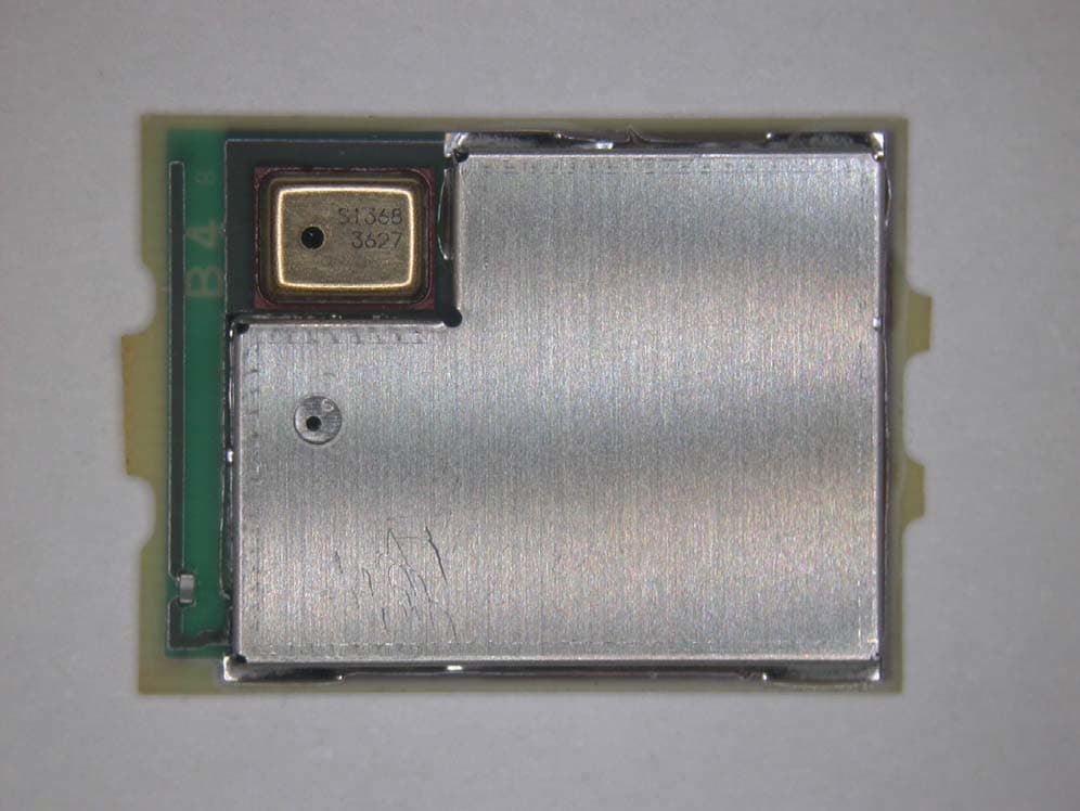
EJE-BT0004
Dec 06, 2015Ubiquitous-warecore module
Equipment Class
DTS - Digital Transmission System
EJE-WB0097
Nov 12, 2015FUJITSU STYLISTIC Q736
Equipment Class
DTS - Digital Transmission System