EJE-WL0001Notebook/Pentablet PC T3010
Fujitsu Client Computing Limited (FCCL)
Click to zoom
Application Details
- Equipment Class
- DTS - Digital Transmission System
- Date of Grant
- Aug 20, 2003
- Application Purpose
- Original Equipment
- Date of Application
- Aug 20, 2003
- Equipment Note
- Notebook/Pentablet PC T3010
- Frequency Range
- 2412.00000000 - 2462.00000000
- Country
- Japan
Documents & Files
Document Text
Text extracted from the exhibit documents filed with the FCC. Open a document above to read the original.
Users Manual
FCC ID: EJE-WL0001 (IC: 337J-WL0001) Report No. M030725_Certification_Mace_Calexico EMC Technologies Pty Ltd. 57 Assembly Drive, Tullamarine VIC 3043 Australia www.emctech.com EMC Technologies Pty Ltd - Report No. M030725_Certification_Mace_Calexico APPENDIX J – USER MANUAL (SUPPLIED TO ALL END USERS) Intel(R) PRO/Wireless LAN Mini PCI Adapter User's Guide This document provides information for the following wireless devices: • Intel(R) PRO/Wireless LAN 2100 3B Mini PCI Adapter, operating at 2.4 GHz These wireless adapters operate with high-capacity networks using multiple access points within large or small environments. Using the Intel(R) PROSet Windows utility you can configure, manage wireless local area network (WLAN) management tasks, adapter switching functions, and connections. Wireless LAN General Information 1.About Wireless LAN Technology Adapter Setup and Configuration 2.Software Installation 3.Using Intel(R) PROSet 4.Connecting to a Network using Intel® PROSet 5.Security Overview 6.Setting Up WEP Encryption and Authentication 7.Troubleshooting 8.Specifications 9.Glossary Support and Warranty 10.Customer Support 11.Software License 12.Safety and Regulatory Notices 13.Limited Warranty 14.Legal Notices Copyright (c) 2003 Intel Corporation. All rights reserved. Intel Corporation, 5200 N.E. Elam Young Parkway, Hillsboro, OR 97124-6497 USA Intel Corporation assumes no responsibility for errors or omissions in this document. Nor does Intel make any commitment to update the information contained herein. Intel, Itanium, and Pentium are trademarks or registered trademarks of Intel Corporation or its subsidiaries in the United States and other countries. *Other names and brands may be claimed as the property of others. 1.About Wireless LAN Technology A wireless network connects computers without using network cables. Computers use radio communications to send data between each other. You can communicate directly with other wireless computers, or connect to an existing network through a wireless access point. When you set up your wireless adapter, you select the operating mode for the kind of wireless network you want. You can use your Intel(R) PRO/Wireless adapter to connect to other similar wireless devices that comply with the 802.11 standard for wireless networking. Choosing a Wireless LAN Mode Wireless LANs can operate with or without access points, depending on the number of users in the network. Infrastructure mode uses access points to allow wireless computers to send and receive information. Wireless computers transmit to the access point, the access point receives the information and rebroadcasts it to other computers. The access point can also connect to a wired network or to the Internet. Multiple access points can work together to provide coverage over a wide area. Peer-to-Peer mode, also called Ad Hoc mode, works without access points and allows wireless computers to send information directly to other wireless computers. You can use Peer-to-Peer mode to network computers in a home or small office or to set up a temporary wireless network for a meeting. Configuring a Wireless LAN There are three basic components that must be configured for a wireless LAN to operate properly: • Network Name—Each wireless network uses a unique Network Name to identify the network. This name is called the Service Set Identifier (SSID). When you set up your wireless adapter, you specify the SSID. If you want to connect to an existing network, you must use the name for that network. If you are setting up your own network you can make up your own name and use it on each computer. The name can be up to 32 characters long and contain letters and numbers. • Profiles —When you set up your computer to access a wireless network, Intel(R) PROSet creates a profile for the wireless settings that you specify. If you want to connect to another network, you can scan for existing networks and make a temporary connection, or create a new profile for that network. After you create profiles, your computer will automatically connect when you change locations. • Security —The 802.11 wireless networks use encryption to help protect your data. Wired equivalent privacy (WEP) uses a 64-bit or 128-bit shared encryption key to scramble data. Before a computer transmits data, it scrambles the data using the secret encryption key. The receiving computer uses this same key to unscramble the data. If you are connecting to an existing network, use the encryption key provided by the administrator of the wireless network. If you are setting up your own network you can make up your own key and use it on each computer. Identifying a Wireless Network Depending on the size and components of a wireless LAN, there are many ways to identify a wireless LAN: • The Network Name or Service Set Identifier (SSID)—Identifies a wireless network. All wireless devices on the network must use the same SSID. • Extended Service Set Identifier (ESSID)—A special case of SSID used to identify a wireless network that includes access points. • Independent Basic Service Set Identifier (IBSSID)—A special case of SSID used to identify a network of wireless computers configured to communicate directly with one another without using an access point. • Basic Service Set Identifier (BSSID) —A unique identifier for each wireless device. The BSSID is the Ethernet MAC address of the device. • Broadcast SSID—An access point can respond to computers sending probe packets with the broadcast SSID. If this feature is enabled on the access point, any wireless user can associate with the access point by using a blank (null) SSID. Surveying the Site of Your Wireless LAN Conducting a site survey for your wireless LAN is the most crucial step in the process of setting up a wireless network. It greatly reduces the amount of troubleshooting you will have to do once you have the wireless LAN set up and ready for connection testing. To conduct a site survey, you will need th…
Text truncated - open the document above for the full version.
Users Manual
Copyright Copyright Fujitsu PC Corporation has made every effort to ensure the accuracy and completeness of this document. However, as ongoing development efforts are continually improving the capabilities of our products, we cannot guarantee the accuracy of the contents of this document. We disclaim liability for errors, omissions, or future changes. Fujitsu, the Fujitsu logo, and LifeBook are registered trademarks of Fujitsu Limited. The following are registered trademarks of Microsoft Corporation: MS, MS-DOS, Windows. PCMCIA is a trademark of the Personal Computer Memory Card International Association. Intel and Pentium are registered trademarks of Intel Corporation. Adobe Acrobat Reader is a registered trademark of Adobe System Inc. PowerQuest and Drive Image are registered trademarks of PowerQuest Corporation. All other trademarks mentioned herein are the property of their respective owners. © Copyright 2003 Fujitsu PC Corporation. All rights reserved. No part of this publication may be copied, reproduced, or translated, without prior written consent of Fujitsu PC Corporation. No part of this publication may be stored or transmitted in any electronic form without the written consent of Fujitsu PC Corporation. B5FH-9011-01EN-00 DECLARATION OF CONFORMITY according to FCC Part 15 Responsible Party Name:Fujitsu PC Corporation Address: 5200 Patrick Henry Drive Santa Clara, CA 95054 Telephone:(408) 982-9500 Declares that product:Model Configuration: LifeBook T3010 Tablet PC LifeBook T3010D Tablet PC Complies with Part 15 of the FCC Rules. This device complies with Part 15 of the FCC rules. Operations are subject to the following two conditions: (1) This device must not be allowed to cause harmful interference, (2) This device must accept any interference received, including interference that may cause undesired operation. T Series.book Page 1 Thursday, July 31, 2003 10:49 AM LifeBook T Series Tablet PC T Series.book Page 2 Thursday, July 31, 2003 10:49 AM Table of Contents Fujitsu LifeBook ® T Series Tablet PC Table of Contents 1 PREFACE Preface About This Guide . . . . . . . . . . . . . . . . . . . . . . . . . 3 FPC Contact Information . . . . . . . . . . . . . . . . . . . 3 Warranty . . . . . . . . . . . . . . . . . . . . . . . . . . . . . . . 3 2 GETTING TO KNOW YOU R TABL ET PC Overview Unpacking . . . . . . . . . . . . . . . . . . . . . . . . . . . . . . 7 Optional Accessories . . . . . . . . . . . . . . . . . . . . . . 8 Locating the Controls and Connectors Top and Front Components . . . . . . . . . . . . . . . . 10 Left-Side Panel Components . . . . . . . . . . . . . . . 11 Right-Side Panel Components . . . . . . . . . . . . . . 12 Rear Panel Components . . . . . . . . . . . . . . . . . . . 13 Bottom Components . . . . . . . . . . . . . . . . . . . . . 14 Status Indicator Panel Power Indicator . . . . . . . . . . . . . . . . . . . . . . . . . 15 AC Adapter Indicator . . . . . . . . . . . . . . . . . . . . . 15 Battery Level Indicators . . . . . . . . . . . . . . . . . . . 15 Battery Charging Indicator . . . . . . . . . . . . . . . . . 16 Hard Drive Access Indicator . . . . . . . . . . . . . . . . 16 NumLk Indicator. . . . . . . . . . . . . . . . . . . . . . . . . 16 CapsLock Indicator . . . . . . . . . . . . . . . . . . . . . . . 16 ScrLk Indicator . . . . . . . . . . . . . . . . . . . . . . . . . . 16 Security Indicator . . . . . . . . . . . . . . . . . . . . . . . . 16 Display Panel Opening the Display Panel . . . . . . . . . . . . . . . . . 17 Using the System as a Tablet . . . . . . . . . . . . . . . 17 Adjusting Display Panel Brightness . . . . . . . . . . . 18 Keyboard Using the Keyboard . . . . . . . . . . . . . . . . . . . . . . 19 Numeric Keypad. . . . . . . . . . . . . . . . . . . . . . . . . 19 Windows Keys . . . . . . . . . . . . . . . . . . . . . . . . . . 19 Cursor Keys . . . . . . . . . . . . . . . . . . . . . . . . . . . . 20 Function Keys . . . . . . . . . . . . . . . . . . . . . . . . . . . 20 LifeBook Security/Tablet PC Buttons Changing Tablet PC Button Functions . . . . . . . . 22 Setting up LifeBook Security Panel . . . . . . . . . . . 22 Passwords . . . . . . . . . . . . . . . . . . . . . . . . . . . . . 22 Using Your LifeBook Security Panel . . . . . . . . . . 23 Uninstalling the Security Panel Application . . . . . 24 Touchpad Pointing Device Clicking . . . . . . . . . . . . . . . . . . . . . . . . . . . . . . . 25 Double-Clicking . . . . . . . . . . . . . . . . . . . . . . . . . 25 Dragging . . . . . . . . . . . . . . . . . . . . . . . . . . . . . . 26 Scrolling . . . . . . . . . . . . . . . . . . . . . . . . . . . . . . . 26 Touchpad Control Adjustment . . . . . . . . . . . . . . 26 Pen and Active Digitizer Using the Pen. . . . . . . . . . . . . . . . . . . . . . . . . . . 27 Calibrating the Pen. . . . . . . . . . . . . . . . . . . . . . . 27 Replacing the Pen Tip . . . . . . . . . . . . . . . . . . . . . 28 Using the Active Digitizer . . . . . . . . . . . . . . . . . . 28 Volume Control Controlling the Volume . . . . . . . . . . . . . . . . . . . 29 3 USING YOUR TABLET PC Power Sources Connecting the Power Adapters . . . . . . . . . . . . . 33 Starting Your Tablet PC Power On. . . . . . . . . . . . . . . . . . . . . . . . . . . . . . 34 Boot Sequence . . . . . . . . . . . . . . . . . . . . . . . . . . 34 BIOS Setup Utility. . . . . . . . . . . . . . . . . . . . . . . . 34 Booting the System . . . . . . . . . . . . . . . . . . . . . . 34 T Series.book Page 3 Thursday, July 31, 2003 10:49 AM LifeBook T Series Tablet PC Activating Additional Utilities . . . . . . . . . . . . . . . 35 Registering Your LifeBook T Series Tablet PC . . . 35 Power Management Suspend/Resume Button . . . . . . . . . . . . . . . . . . 36 Standby Mode . . . . . . . . . . . . . . . . . . . . . . . . . . 36 Hibernate Mode. . . . . . . . . . . . . . . . . . . . . . . . . 37 Display Timeout . . . . . . . . . . . . . . . . . . . . . . . . . 37 Hard Disk Timeout . . . . . . . . . . . . . .…
Text truncated - open the document above for the full version.
Users Manual
FCC ID: EJE-WL0001 (IC: 337J-WL0001) Report No. M030725_Certification_Mace_Calexico EMC Technologies Pty Ltd. 57 Assembly Drive, Tullamarine VIC 3043 Australia www.emctech.com EMC Technologies Pty Ltd - Report No. M030725_Certification_Mace_Calexico ANNEX K – EUT HOST SPECIFICATIONS 28 Jul 03 Rev 3.0 (FJ Spec Rev 1.4) Mace Latest Intel Centrino Mobile Technology Seamless Wi-Fi Connectivity 12.1" XGA TFT Active Digitizer 2GB Maximum Memory support Programmable Security Feature Mace T3010 CPU Intel ® Pentium ® M Processor 1.4GHz Secondary Cache1MB ChipsetIntel 855GM Memory256MB SDRAM, Max. 2GB (DDR266) Hard Disk Drive40GB (Ultra DMA/100 and S.M.A.R.T. Support) Display12.1" XGA TFT Colour (Max 1024x768 dots) LCD TypeTransmissive DigitizerActive (Electromagnetic) GraphicsIntegrated Intel® Graphics w/ Dynamic Video Memory Technology with 3D Graphics Accelerator and AGP and MPEG-2 Support (for DVD) SoundAC Link Audio (AC97 compliance: ALC202) with Internal Speaker, Internal Microphone CommunicationV.90 Modem & 10/100Mbps LAN Wireless LANIntel® PRO/Wireless 2100 - 802.11b with Dual Antenna OR Broadcom Wireless 11b/11g External I/O Interface1xVGA, 2xUSB 2.0, 1xRJ11, 1xRJ45, Audio (Headphone-out, Microphone-in), Docking for Port Replicator, AC Adapter Power Input Port Replicator1xVGA, 2xUSB 2.0, 1xRJ45, AC Adapter Power Input Security PanelApplication Mode: Application Launch Buttons and 2 programmable buttons Security Mode: Unique Numeric Buttons for Security Lock (More than 800,000 possible password combinations) Keyboard82-key w/ 19mm Key Pitch, 3mm Key Stroke Pointing DeviceTouch Pad with Scroll button Card SlotPC Card Slot Type I/II x 2 IR InterfaceIrDA1.1 ( Max. 4Mbps ) AC AdapterInput: AC100-240V, Output: DC16V 60W Battery*Approx. 4.4 hours, Lithium-Ion OS SupportedMicrosoft® Windows® XP Tablet PC Edition Other Software BundledNorman Virus Control Norman Personal FireWall Dimensions293mm(W) x 236mm(D) x 27.4mm min. (H) WeightApprox. 1.9Kg
Cover Letter(s)
Federal Communications Commission Equipment Authorization Division Application Processing Branch 7435 Oakland Mills Road Columbia, MD 21045 Date: 01/08/2003 Reference: FCC ID: EJE-WL0001 Subject: Request for Confidentiality for FCC Certification Application Company: FUJITSU Test Sample: Mini-PCI Wireless LAN Module (Calexico) Product Type: - Low power transmitter (intentional radiator) Pursuant to Rule 47 CFR, Chapter 1, Section 0.457(d)(1)(ii), FUJITSU requests that prior to the equipment authorization grant for the (test sample), the entire application be classified and deemed confidential by the Federal Communications Commission (FCC) and as such be withheld from public inspection. As per 47 CFR, Chapter 1, Section 0.457, the exhibits tendered for the purpose of this grant, contain details of trade secrets and technical data that is not made available to competitors and the general public. This information is treated in a confidential manner by FUJITSU and guarded from disclosure to our competitors. The exhibits outlined below are not routinely made available to FUJITSU staff, with such access granted only to those specifically involved with this particular project. They contain information detailing the unique technology and circuitry of the product that would be of significant benefit to our competitors. All employees treat this technical data in a confidential manner. The manufacture of this product has taken place after an extensive research and development process that has seen the company invest a considerable amount of time and money. The time and effort taken has enabled the product to meet the specific demands of the competitive market for which it is intended and it would be therefore detrimental to allow competitors easy access to design and development details. Apart from a limited number of employees, the information has previously only been disclosed to the Test House responsible for conducting testing and authorized to act as our agent during the certification process. Pursuant to 47CFR Chapter 1, Section 0.459, post-grant confidentiality is requested for the following items, ensuring that this material continue to be withheld from public inspection following the grant. Exhibits – Technical PCB Layouts, Technical Schematic Circuit Diagrams, Detailed Antenna Information Sincerely Yours, Kanbe Katsuhito Fujitsu Japan Mobile Computing Division FUJITSU LIMITED 1405 Ohmaru, Inagi-shi, Tokyo 206-8503, Japan Tel(+81-42)370-7632 FAX(+81-42)370-7708 Mobile Computing Division
Cover Letter(s)
EMC Technologies Pty. Ltd., 57 Assembly Dve., Tullamarine, Vic., 3043, Australia. Phone : +61 3 9335 3333 Fax: +61 3 9338 9260 www.emctech.com.au FCC ID: EJE-WL0001 and EJE-WL0002 Date: 14 h August 2003 EMC Reference: M030726 Subject: Response to FCC Queries Q1. Please specify the probe tip diameter of the SAR measurement system. Has this been addressed somewhere in the report? The diameter of our probe tip is 7mm for the SN1380, this was not addressed in the SAR reports. Q2. On page 10 of the test report the target dielectric parameters of the brain simulating liquid are listed as 39.8 and 1.88. Supplement C lists these values as 39.2 and 1.80. Please clarify this difference. The dielectric parameters of the SAR liquid were referenced from page 36 of OET Bulletin 65C under the table listed “TYPICAL COMPOSITION OF INGREDIENTS FOR LIQUID TISSUE PHANTOMS”. This was simply an interpretation error and the oversight did not have any influence on the SAR results. The validations performed on each day were within the required 10% tolerance and the brain liquid was within 5% tolerance of the required dielectric parameters on the 1 st and 5 th to 7 th August. On the 4 th of August the liquid parameters were within 6%. The higher conductivity tends to overestimate the SAR validation result as shown by the deviation from IEEE reference values listed in table 3 of the SAR reports. The dielectric properties of the body liquid (used in all laptop configurations) were within the required 5% tolerance on all test days. Q3. Are there 2 antennas on the top of the LCD screen? (One on the left and another on the right). If this is the case, does the SAR data presented represent the worst readings? Please clarify this as well. Yes there are two antennas located on top of the LCD screen (one on the left and one on the right). One of these antennas is receive only and does not have any impact on the measured SAR levels. The pre-scans performed in each position define the location of the SAR hot spots and the corresponding locations of the transmitting antenna. The SAR levels measured are conservative and represent the worst-case scenario. EMC Technologies Pty Ltd ABN 82 057 105 549 57 Assembly Drive Tullamarine Victoria Australia 3043 Ph: + 613 9335 3333 Fax: + 613 9338 9260 email: [email protected]
Cover Letter(s)
Response to TCB EMC Findings Q: Please supply the Declaration of Conformity Form of the host Notebook PC Model T3010. Response: Supplied.
External Photos
FCC ID: EJE-WL0001 (IC: 337J-WL0001) Report No. M030725_Certification_Mace_Calexico EMC Technologies Pty Ltd. 57 Assembly Drive, Tullamarine VIC 3043 Australia www.emctech.com EMC Technologies Pty Ltd - Report No. M030725_Certification_Mace_Calexico APPENDIX B3 – EUT Host PC Photographs FCC ID: EJE-WL0001 (IC: 337J-WL0001) Report No. M030725_Certification_Mace_Calexico EMC Technologies Pty Ltd. 57 Assembly Drive, Tullamarine VIC 3043 Australia www.emctech.com APPENDIX B3 Host – LifeBook T Series – Model T3010 (Mace) FCC ID: EJE-WL0001 (IC: 337J-WL0001) Report No. M030725_Certification_Mace_Calexico EMC Technologies Pty Ltd. 57 Assembly Drive, Tullamarine VIC 3043 Australia www.emctech.com APPENDIX B3 Host – LifeBook T Series – Model T3010 (Mace)
Internal Photos
FCC ID: EJE-WL0001 (IC: 337J-WL0001) Report No. M030725_Certification_Mace_Calexico EMC Technologies Pty Ltd. 57 Assembly Drive, Tullamarine VIC 3043 Australia www.emctech.com EMC Technologies Pty Ltd - Report No. M030725_Certification_Mace_Calexico APPENDIX B1 – TEST SAMPLE PHOTOGRAPHS FCC ID: EJE-WL0001 (IC: 337J-WL0001) Report No. M030725_Certification_Mace_Calexico EMC Technologies Pty Ltd. 57 Assembly Drive, Tullamarine VIC 3043 Australia www.emctech.com APPENDIX B1 Test Sample – Wireless LAN Module (Calexico), Model WM3B2100-Mace
Internal Photos
FCC ID: EJE-WL0001 (IC: 337J-WL0001) Report No. M030725_Certification_Mace_Calexico EMC Technologies Pty Ltd. 57 Assembly Drive, Tullamarine VIC 3043 Australia www.emctech.com EMC Technologies Pty Ltd - Report No. M030725_Certification_Mace_Calexico APPENDIX B4 – EUT & ANTENNA LOCATION FCC ID: EJE-WL0001 (IC: 337J-WL0001) Report No. M030725_Certification_Mace_Calexico EMC Technologies Pty Ltd. 57 Assembly Drive, Tullamarine VIC 3043 Australia www.emctech.com APPENDIX B4 EUT & ANTENNA LOCATION WLAN Location (Exploded view) Antenna WLAN FCC ID: EJE-WL0001 (IC: 337J-WL0001) Report No. M030725_Certification_Mace_Calexico EMC Technologies Pty Ltd. 57 Assembly Drive, Tullamarine VIC 3043 Australia www.emctech.com APPENDIX B4 EUT & ANTENNA LOCATION Antenna
RF Exposure Info
FCC ID: EJE-WL0001 IC: 337J-WL0001 Report No. M030726_MACE_CALEXICO_SAR Page 1 of 39 This document shall not be copied or reproduced, except in full without the written permission of the Technical Director , EMC Technologies Pty. Ltd. www. emctech.com.au SAR Test Report Report Number: M030726_MACE_CALEXICO_SAR Test Sample: Portable Tablet Computer Wireless LAN Model Number: WM3B2100-MACE Tested For: Fujitsu Australia Pty Ltd FCC ID: EJE-WL0001 IC: 337J-WL0001 Date of Issue: 4 th August 2003 EMC Technologies Pty Ltd reports apply only to the specific samples tested under stated test conditions. It is the manufacturer’s responsibility to assure that additional production units of this model are manufactured with identical electrical and mechanical components. EMC Technologies Pty Ltd shall have no liability for any deductions, inferences or generalisations drawn by the client or others from EMC Technologies Pty Ltd issued reports. This report shall not be used to claim, constitute or imply product endorsement by EMC Technologies Pty Ltd. EMC Technologies Pty Ltd A.C.N. 057 105 549 57 Assembly Drive Tullamarine Victoria Australia 3043 Ph: + 613 9335 3333 Fax: + 613 9338 9260 email: [email protected] FCC ID: EJE-WL0001 IC: 337J-WL0001 Report No. M030726_MACE_CALEXICO_SAR Page 2 of 39 This document shall not be copied or reproduced, except in full without the written permission of the Technical Director , EMC Technologies Pty. Ltd. www. emctech.com.au CONTENTS 1.0 GENERAL INFORMATION........................................................................................................... 3 2.0 DESCRIPTION OF DEVICE..........................................................................................................4 2.1 Description of Test Sample .................................................................................................. 4 2.1.1 Summary of EUT Details .................................................................................................. 4 2.1.2 EUT Host Details .............................................................................................................. 5 2.2 Test sample Accessories ..................................................................................................... 5 2.2.1 Battery Types ...................................................................................................................5 2.3 Test Signal, Frequency and Output Power........................................................................... 5 2.4 Battery Status....................................................................................................................... 5 2.5 Details of Test Laboratory .................................................................................................... 6 2.5.1 Location............................................................................................................................ 6 2.5.2 Accreditations ................................................................................................................... 6 2.5.3 Environmental Factors...................................................................................................... 6 3.0 DESCRIPTION OF SAR MEASUREMENT SYSTEM ................................................................... 7 3.1 Probe Positioning System .................................................................................................... 7 3.2 E-Field Probe Type and Performance .................................................................................. 7 3.3 Data Acquisition Electronics ................................................................................................. 7 3.4 Calibration and Validation Procedures and Data .................................................................. 7 3.4.1 Validation Results @ 2450MHz ........................................................................................ 7 3.4.2 Deviation from reference validation values ....................................................................... 8 3.4.3 Liquid Depth 15cm............................................................................................................ 8 3.5 Phantom Properties (Size, Shape, Shell Thickness) ............................................................ 9 3.6 Tissue Material Properties.................................................................................................. 10 3.6.1 Liquid Temperature and Humidity................................................................................... 11 3.7 Simulated Tissue Composition Used for SAR Test ............................................................ 11 3.8 Device Holder for Laptops and PL550 Phantom ................................................................ 11 4.0 SAR MEASUREMENT PROCEDURE USING DASY4 ............................................................... 12 5.0 MEASUREMENT UNCERTAINTY.............................................................................................. 13 6.0 EQUIPMENT LIST AND CALIBRATION DETAILS .................................................................... 15 7.0 OET BULLETIN 65 – SUPPLEMENT C TEST METHOD ........................................................... 16 7.1 Description of the Test Positions (Lap Top)........................................................................ 16 7.1.1 “Tablet” Position Definition (0mm spacing) ..................................................................... 16 7.1.2 “Laptop no spacer” Position (0mm spacing) ................................................................... 16 7.1.3 “Lap Arm Held” Position (0mm spacing) ......................................................................... 16 7.1.4 “Back of Lid” Position (0mm spacing) ............................................................................. 16 7.2 List of All Test Cases (Antenna In/Out, Test Frequencies, User Modes) ............................…
Text truncated - open the document above for the full version.
RF Exposure Info
FCC ID: EJE-WL0001 IC: 337J-WL0001 Report No. M030726_MACE_CALEXICO_SAR Page 26 of 39 This document shall not be copied or reproduced, except in full without the written permission of the Technical Director , EMC Technologies Pty. Ltd. www. emctech.com.au APPENDIX B PLOTS OF THE SAR MEASUREMENTS Plots of the measured SAR distributions inside the phantom are given in this Appendix for only the “Lap Arm Held” and “Back of lid” tested configurations only. The spatial peak SAR values were assessed with the procedure described in this report. NOTE on SAR Plots: The measured SAR levels in the Tablet and Laptop positions were < 0.01mW/g (less than the required ambient noise level, per p1528-2003) and consequently the hotspot was not always clearly defined. The plots and graphs for these positions are not included because the measurement results are within the noise floor and measurement sensitivity of the SAR system and do not have any significance for compliance purposes. NOTE on SAR Graphs: The Z-axis scans listed in this appendix do not always show a consistent decay over distance. It is our opinion that this is not due to an incorrect liquid level but caused by a much lower than average SAR level, a metallic laptop case and fields that have very steep gradients. The steep gradients occur because a small high frequency source is placed very close to the tissue. It is also suspected that the metallic case of the laptop causes reflections and inconsistencies close to the phantom surface. For reference the Validation Z-axis scans show the expected field decay over distance. Table 15: 2450 MHz DSSS Band SAR Measurement Plot Numbers Plot 1 Lap Arm Held Position – CH#01 Page 26 Plot 2 Lap Arm Held Position – CH#06 Page 27 Plot 3 Lap Arm Held Position – CH#11 Page 28 Plot 4 Back of Lid Position – CH#01 Page 29 Plot 5 Back of Lid Position – CH#06 Page 30 Plot 6 Back of Lid Position – CH#11 Page 31 Z-Axis Graphs Z-Axis graphs for Plots 1 to 6 Pages 32-34 Table 16: 2450MHz Validation Plot Plot 7 Validation 2450MHz 6 th August 2003 Page 35 Plot 8 Validation 2450MHz 7 th August 2003 Page 36 Z-Axis Graphs Z-Axis graphs for Plots 7 to 8 Pages 37-38 FCC ID: EJE-WL0001 IC: 337J-WL0001 Report No. M030726_MACE_CALEXICO_SAR Page 27 of 39 This document shall not be copied or reproduced, except in full without the written permission of the Technical Director , EMC Technologies Pty. Ltd. www. emctech.com.au Test Date: 06 August 2003 File Name: Arm Held DSSS Tablet 06-08-03.da4 DUT: Fujitsu Notebook with WLAN; Type: Mace B1; Serial: No.59 * Communication System: DSSS 2450 MHz; Frequency: 2412 MHz; Duty Cycle: 1:1 * Medium: Body 2450 MHz; (σ = 1.95938 mho/m, ε r = 52.1071, ρ = 1000 kg/m 3 ) - Electronics: DAE3 Sn442; Probe: ET3DV6 - SN1380; ConvF(4.5, 4.5, 4.5) - Phantom: Flat Phantom 10.1; Serial: P 10.1; Phantom section: Flat 2.2 Section Channel 01 Test 2/Area Scan (71x71x1): Measurement grid: dx=15mm, dy=15mm Reference Value = 5.96 V/m Power Drift = -0.2 dB Maxi…
Text truncated - open the document above for the full version.
Contact Information
Applicant
Mr. Tsuyoshi Uchihara(Engineer)
Test Firm
Lexmark International, Inc.John Fessler
Technical Specifications
| # | Rule Parts | Frequency Range | Power Output |
|---|---|---|---|
| 1 | 15C | 2.41 GHz - 2.46 GHz | 33.20 mW |
Other Applications from Fujitsu Client Computing Limited (FCCL)
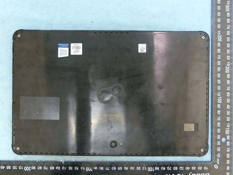
EJE-KST001
May 13, 2020Tablet Computer
Equipment Class
DXX - Part 15 Low Power Communication Device Transmitter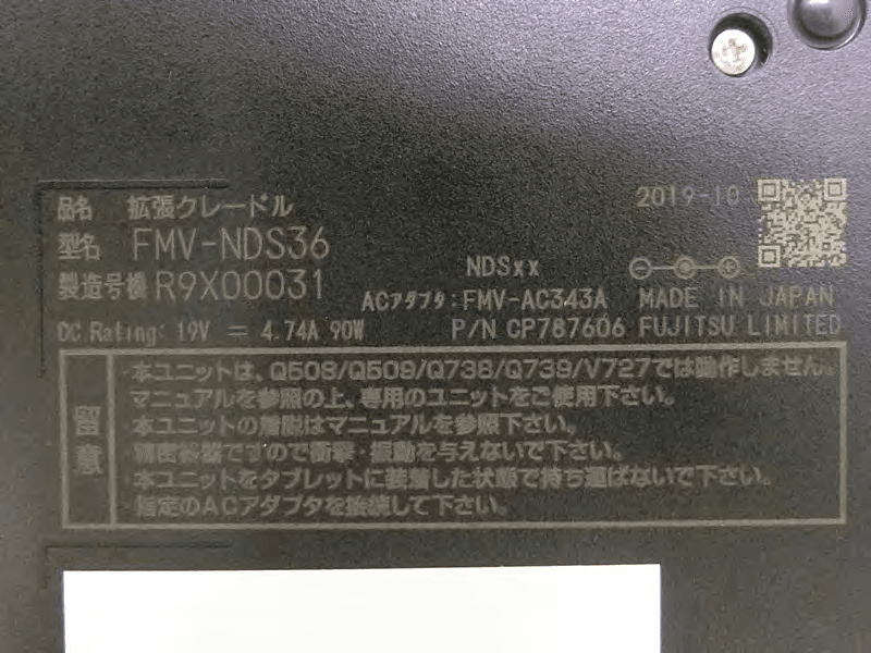
EJE-KSC001
May 13, 2020Port Replicator
Equipment Class
DXX - Part 15 Low Power Communication Device Transmitter
EJE-WB0099
Jan 27, 2016STYLISTIC Q series
Equipment Class
DSS - Part 15 Spread Spectrum Transmitter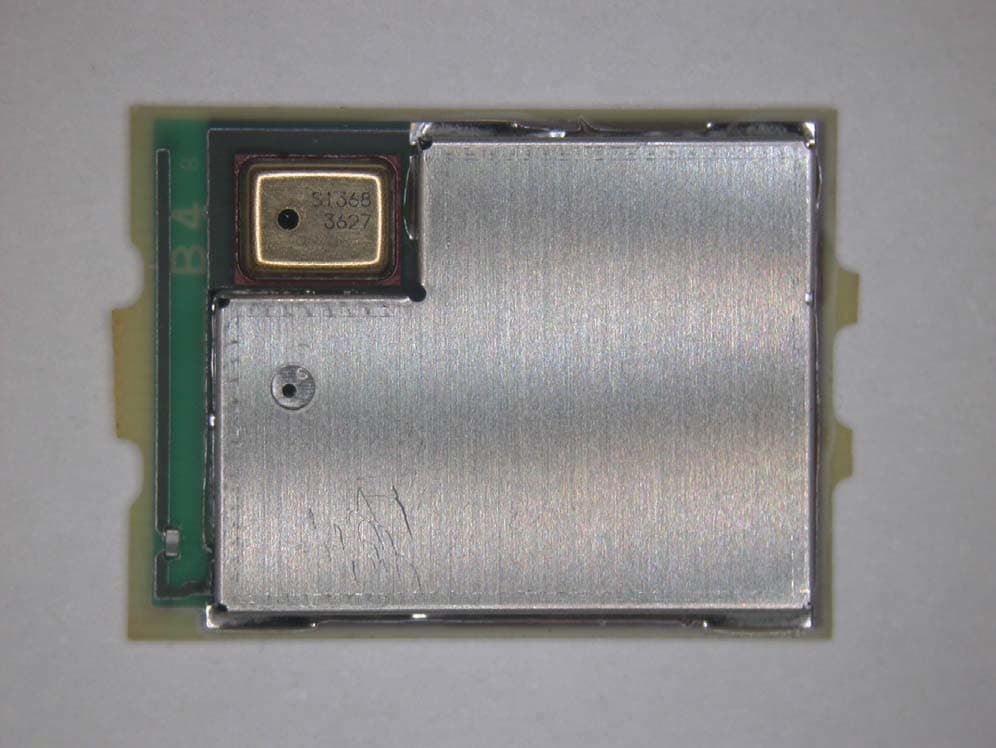
EJE-BT0004
Dec 06, 2015Ubiquitous-warecore module
Equipment Class
DTS - Digital Transmission System
EJE-WB0097
Nov 12, 2015FUJITSU STYLISTIC Q736
Equipment Class
DTS - Digital Transmission System