EJE-WL0005Stylistic ST Series Pentablet PC & WLAN
Fujitsu Client Computing Limited (FCCL)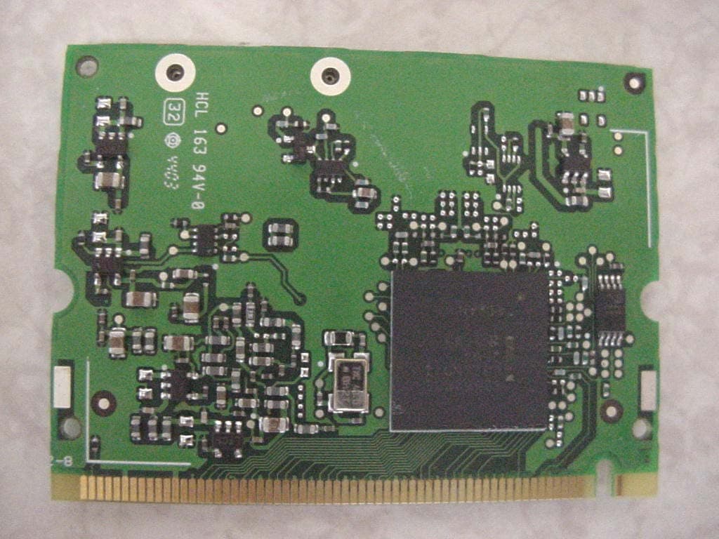
Click to zoom
Application Details
- Equipment Class
- DTS - Digital Transmission System
- Date of Grant
- Mar 03, 2004
- Application Purpose
- Original Equipment
- Date of Application
- Mar 03, 2004
- Equipment Note
- Stylistic ST Series Pentablet PC & WLAN
- Frequency Range
- 2412.00000000 - 2462.00000000
- Country
- Japan
Documents & Files
Document Text
Text extracted from the exhibit documents filed with the FCC. Open a document above to read the original.
Users Manual
Copyright Fujitsu Computer Systems Corporation has made every effort to ensure the accuracy and completeness of this document. Because ongoing development efforts are made to continually improve the capabilities of our prod- ucts, however, the data contained herein represents Fujitsu design objectives and is provided for comparative purposes; actual results may vary based on a variety of factors. This product data does not constitute a warranty. Specifications are subject to change without knowledge. Fujitsu and the Fujitsu logo are registered trademarks of Fujitsu Limited; Stylistic is a registered trademark of Fujitsu Computer Systems Corporation. Microsoft and Windows are registered trademarks of Microsoft Corporation. PCMCIA and CardBus are registered trademarks of the Personal Computer Memory Card International Associa- tion. Intel, Pentium, and SpeedStep are registered trademarks of Intel Corporation. Atheros is a registered trademark of Atheros Communi- cations, Inc. PowerQuest and Drive Image are registered trademarks of PowerQuest Corp. Kensington and MicroSaver are registered trademarks of the Kensington Technology Group. SanDisk and the SanDisk logo are registered trademarks of SanDisk Corporation. Memory Stick is a registered trademark of Sony Corpora- tion and/or its affiliates Wi-Fi is a trademark of the Wireless Ethernet Compati- bility Alliance (WECA). All other products are trademarks or registered trade- marks of their respective companies. Copyright 2004-Fujitsu Computer Systems Corporation. All rights reserved. No part of this publication may be copied, reproduced, or translated, without the prior written consent of Fujitsu Computer Systems Corpora- tion. No part of this publication may be stored or trans- mitted in any electronic form without the prior consent of Fujitsu Computer Systems Corporation. B6FH-0561-02EN-00 Note:For more detailed information about the FCC rules and their applicability to the Stylistic ST5000 Series Tablet PC, refer to Chapter 5 of this document. Warning Handling the cord on this product will expose you to lead, a chemical known to the State of California to cause birth defects or other reproductive harm. Wash hands after handling. DECLARATION OF CONFORMITY according to FCC Part 15 Responsible Party Name:Fujitsu Computer Systems Corporation Address:1250 E. Arques Avenue, MS 122 Sunnyvale, CA 954085 Telephone:408-746-6000 Declares that product:Model Series: Stylistic® ST5000 Tablet PC Complies with Part 15 of the FCC Rules This device complies with Part 15 of the FCC rules. Operation is subject to the following two conditions: (1) This device may not cause harmful interference, and, (2) This device must accept any interference received, including interference that may cause undesired operation. Stylistic ST5000 Series Tablet PC - User’s Guide Table of Contents Table of Contents PREFACE About This Guide . . . . . . . . . . . . . . . . . . . . . . . . . v Fujitsu Contact Information . . . . . . . . . . . . . . . . . v Warranty Information . . . . . . . . . . . . . . . . . . . . . v 1 GETTING STARTED WITH YOUR TABLET PC Getting Started In-box Items for the Stylistic ST5000 Series Tablet PC . . . . . . . . . . . . . . . . . . 1 Optional Accessories . . . . . . . . . . . . . . . . . . . . . . 2 Stylistic Tablet PC Features. . . . . . . . . . . . . . . . . . 3 Status Display. . . . . . . . . . . . . . . . . . . . . . . . . . . . 8 Application Buttons . . . . . . . . . . . . . . . . . . . . . . 10 Navigation Buttons. . . . . . . . . . . . . . . . . . . . . . . 12 Tertiary Functions of Application and Navigation Buttons. . . . . . . . . . . . . . . . . . 13 Security Functions of Application Buttons. . . . . . 14 Setting up the Security Panel . . . . . . . . . . . . . . . 14 Passwords . . . . . . . . . . . . . . . . . . . . . . . . . . . . . 14 Using Your Security Panel . . . . . . . . . . . . . . . . . 15 Precautions . . . . . . . . . . . . . . . . . . . . . . . . . . . . 15 Uninstalling the Security Panel Application . . . . . 15 Connectors and Peripheral Interfaces . . . . . . . . . 17 2 USING YOUR TABLET PC Using the Stylistic ST5000 Series Tablet PC System States . . . . . . . . . . . . . . . . . . . . . . . . . . . 21 Powering Up the Tablet PC . . . . . . . . . . . . . . . . 22 Shutting Down the System. . . . . . . . . . . . . . . . . 22 Suspending System Operation . . . . . . . . . . . . . . 22 Resuming System Operation . . . . . . . . . . . . . . . 24 Adjusting the Display Brightness. . . . . . . . . . . . . 24 Using the Pen. . . . . . . . . . . . . . . . . . . . . . . . . . . 24 Calibrating the Pen . . . . . . . . . . . . . . . . . . . . . . 25 Installing a Pen Tether . . . . . . . . . . . . . . . . . . . . 25 Replacing the Pen Tip . . . . . . . . . . . . . . . . . . . . 25 Charging the Battery . . . . . . . . . . . . . . . . . . . . . 26 Removing and Installing the Battery. . . . . . . . . . 26 Tips for Conserving Battery Power . . . . . . . . . . . 27 Modem Connection . . . . . . . . . . . . . . . . . . . . . 27 Memory Stick/SD Card Slot . . . . . . . . . . . . . . . . 27 PC Card Slot . . . . . . . . . . . . . . . . . . . . . . . . . . . 28 Removing and Installing Memory Modules . . . . 28 3 CARE AND MAINTENANCE Care and Maintenance Caring for Your Tablet PC . . . . . . . . . . . . . . . . . 33 Protecting the Display Screen. . . . . . . . . . . . . . . 33 Storing the Tablet PC . . . . . . . . . . . . . . . . . . . . . 34 Avoiding Overheating . . . . . . . . . . . . . . . . . . . . 34 Cleaning the Display Screen . . . . . . . . . . . . . . . . 34 Troubleshooting. . . . . . . . . . . . . . . . . . . . . . . . . 34 Restoring Your Pre-Installed Software . . . . . . . . 35 Drive Image Special Edition (DISE) . . . . . . . . . . . 36 4 SPECIFICATIONS Stylistic ST5000 Series Hardware Specifications Physical Specifications . . . . . . . . . . . . . . . . . . . . 41 Processing Specifications . . . . . . . . . . . . . . . . . . 41 Memory/Storage Spec…
Text truncated - open the document above for the full version.
Cover Letter(s)
Page 1 of 2 _____________________________________________________________________ EMC Technologies Pty Ltd, 57 Assembly Drive, Tullamarine VIC 3043 Australia www.emctech.com.au To: ATCB Fax: Attention: Timothy R Johnson Phone: From: EMC Technologies Pty. Ltd. No of pages: 2 EMC Ref: ATCB Query-3 response Date: 4 th March 2004 Subject: Information Request 1) While your conclusion regarding the LCD displays appears logical in certain cases, we are not aware of any published official interpretation from the FCC regarding this issue. Please provide a copy of this interpretation for our review. Please note that we have seen LCD displays with/without metal backings or different circuitry which can affect the results of SAR. While similar construction around the antenna area (including metal) may be reasonable for your conclusion, information regarding the construction around the antennas (i.e. internal photos comparing these areas and/or detailed explanations of the metallic component differences around the antennas, etc.) has not been provided to us. Yes, we understand your concerns. The manufacturer has written to the FCC and obtained a ruling or acceptance after providing similar details as what is being submitted here to ATCB. The FCC email correspondence has been included in the attachment provided for this item. The same document is attached here after including the Antenna photos of the Ocampa models. The manufacturer further states that the Antenna Board, LCD surroundings are identical in both Ocampa ST5010 and Ocampa ST5011. The ST5010D/ST5011D has a FCC Grant (FCC direct submission) already in similar circumstances where this Grant was for a different WLAN module. We do not have references to any official interpretation other than the email correspondence provided and the fact that a Grant has been issued for an identical case. The manufacturer has also stated that the Intel Calexico2 WLAN module and the Antenna boards are NOT specific for any Ocampa models. These items are common for ST5010 and ST5011 Ocampa models. This assembly is done by the manufacturer of the host unit Ocampa in a factory environment and the user is warned NOT to modify this assembly. On this note we would like to advise that we will do another verification SAR test on the second Ocampa for the worst case and submit this along with Item 3 results. 2) Please note that we will accept the power discussion provided. However, in the future please be aware that the FCC asks the power to be compared so that variances in test labs (where 2 labs perform the tests), and/or samples(where multiple samples are assessed), and/or changes to the device can be determined. We have seen in rare instances where samples with the same settings have yielded significant difference of power or where the sample begins to behave differently at a later date (variety of reason). Without an adequate "apples - to - apples" comparison, the fact that the power is >= to the EMC can not be assured. OK. Thanks. We note your points. 3) Since it is likely that only a small difference will be seen due to the retest due to the lowest measurement point, andthe fact that any difference noted is not likely to cause non-compliance due to the low SAR value obtained, we willgo ahead and issue the grant under the following conditions: a) Because of FCC requirements, please note that we will still need the retest information. Therefore, please provide the results of your retest as soon as possible. Please note that a complete retest is not deemed necessary; only the worse case positions. However, we must EMC Technologies Pty Ltd ABN 82 057 105 549 57 Assembly Drive Tullamarine Victoria Australia 3043 Ph: + 613 9335 3333 Fax: + 613 9338 9260 email: [email protected] Page 2 of 2 _____________________________________________________________________ EMC Technologies Pty Ltd, 57 Assembly Drive, Tullamarine VIC 3043 Australia www.emctech.com.au have this information within the next 14 days to properly update the filing and adjust grant if necessary. b) further detail in support of issue 1 above is provided. This will be provided to you within the next few days.
Cover Letter(s)
EMC Technologies Pty. Ltd., 57 Assembly Dve., Tullamarine, Vic., 3043, Australia. Phone : +61 3 9335 3333 Fax: +61 3 9338 9260 www.emctech.com.au FCC ID: EJE-WL0005 Date: 1 st March 2004 EMC Reference: M040122 Subject: Response to ATCB Queries Item 1: The difference between the ST5010 and ST5011 is the LCD screen size. Please see attached document for details. Item 2: See file attached - Test Sample internal photos Item 3: The computer shown for the OATS radiated emissions is identical to that shown for Conducted test set-up. This tablet PC is mounted on a docking station which can be oriented in Portrait OR Landscape positions. The conducted set-up is shown in Landscape orientation and the Radiated set- up is shown in Portrait orientation. Both Antenna polarities were tested and the orientation makes no change to the results. Item 4: Please refer to attached revised test report for results with higher resolution bandwidth & Appendix A for Measurement Instrumentation details. Please replace the original report with the attached. Item 5: As per page 11 of the test report: The out of Band emissions at the Bandedge of 2400 MHz was 36.7 dBuV/m @ 3m when the EUT was operating at its lowest channel (2412 MHz) with 1 MHz resolution bandwidth. The peak output power (using RF conducted test setup) of 102mW was performed with the RBW = 10MHz. The Bandedge plots (using RF conducted test setup) with 100 kHz RBW show that any emissions outside the operating band that were produced by the intentional radiator were at least 20 dB below the fundamental level. Item 5a: The power ratings in SAR report are measured with an average power meter (average power in dBm). The peak output power results in the EMC report are measured using a spectrum analyser. The results take into consideration the antenna gain and the cable loss. Item 6: This was an oversight in the report please see updated report (SAR report part 1 of 6). Item 7: • The Z-axis graphs in the SAR report are shown in dB rather than mW/g this is why the relationship is linear. • The Z-axis graphs shown in this report are all referenced to the maximum SAR level as listed in the corresponding plots. The measurement graphs show the Z-axis graphs up to the 0dB maximum SAR level only. For the tests performed on the laptops, the maximum SAR level was not measured at the lowest probe measuring point. This is why the Z-axis plots do not the expected decay and lower measurement points. EMC Technologies Pty Ltd ABN 82 057 105 549 57 Assembly Drive Tullamarine Victoria Australia 3043 Ph: + 613 9335 3333 Fax: + 613 9338 9260 email: [email protected] Page 2 of 2 The validation Z-axis scans show a more expected z-axis decay from the 0dB maximum SAR value. Item 8: The manual is common to other countries. The operational frequency range for the USA is shown in section 2.3 of the test report as 2412 to 2462 MHz, and the manufacturer confirmed in this response.
Cover Letter(s)
Page 1 of 2 _____________________________________________________________________ EMC Technologies Pty Ltd, 57 Assembly Drive, Tullamarine VIC 3043 Australia www.emctech.com.au To: ATCB Fax: Attention: Timothy R Johnson Phone: From: EMC Technologies Pty. Ltd. No of pages: 2 EMC Ref: ATCB Query-2 response Date: 3 rd March 2004 Subject: Information Request Question 1: Please see corrected document showing both front and rear of the host units. Question 2: Correct. They are the 2 models ST5010 and ST5011. Question 3: As per page 11 of Test Report - M040123_Certification_Ocampa2_Calexico2: "The field strength at 2400 MHz when the EUT was operating at its lowest channel (2412 MHz), was 36.7 dBμV/m peak (noise floor) and was > 20 dB below the maximum field strength of the in-band carrier". Refer to supporting plot (1-7 GHz), Raw peak reading at 2400 MHz ~ 13 dBuV. Cable Loss, Antenna Factor & PreAmp Gain are 23.7 dB and Field Strength at 2400 MHz is 36.7 dBuV/m @ 3m (Peak). Therefore the peak reading in the restricted band 2310-2390 MHz is lower than the peak reading at 2400 MHz. This method is also applied to the restricted band 2483.5-2500 MHz. Question 4: Please refer to document comparing the 2 Ocampa model (supplied for Question 1). FCC ruling has been obtained that NO additional SAR tests are required for the change in Host LCD screen size. The WLAN module, The Antenna models and their locations are identical in both Ocampa models. Question 5: The EUT was configured for maximum power setting - 802.11b = 18 dBm and 802.11g = 15 dBm and the following tests were performed: As required by SAR Test Procedures, an Average Power measurement is required. An Average Power meter was used to measure the Average Power at the Antenna (source point) port. RESULTS: Modulation Mode Channel Channel Frequency MHz Antenna Battery Type Maximum Conducted Average Output Power Measured 802.11b - DSSS 01 2412 Aux 4400mAh 14.19dBm 802.11b - DSSS 06 2437 Aux 4400mAh 14.06dBm 802.11b - DSSS 11 2462 Aux 4400mAh 14.27dBm 802.11g - OFDM 01 2412 Aux 4400mAh 8.91dBm 802.11g - OFDM 06 2437 Aux 4400mAh 9.08dBm 802.11g - OFDM 11 2462 Aux 4400mAh 9.25dBm 802.11b - DSSS 01 2412 Main 4400mAh 14.54dBm 802.11b - DSSS 06 2437 Main 4400mAh 14.23dBm 802.11b - DSSS 11 2462 Main 4400mAh 14.38dBm 802.11g - OFDM 01 2412 Main 4400mAh 9.14dBm 802.11g - OFDM 06 2437 Main 4400mAh 9.18dBm 802.11g - OFDM 11 2462 Main 4400mAh 9.24dBm EMC Technologies Pty Ltd ABN 82 057 105 549 57 Assembly Drive Tullamarine Victoria Australia 3043 Ph: + 613 9335 3333 Fax: + 613 9338 9260 email: [email protected] Page 2 of 2 _____________________________________________________________________ EMC Technologies Pty Ltd, 57 Assembly Drive, Tullamarine VIC 3043 Australia www.emctech.com.au As required by EMC Test Procedures, a Peak Power measurement was performed. A Spectrum Analyser was used to measure the Peak Power level at the same antenna port. RESULTS: Configuration 802.11b Configuration 802.11g To address your query (Item 5): If Average Power measured for both EMC & SAR, then the power levels would be the same. Similarly if Peak power was measured for both EMC & SAR, then the power levels would be the same. The Power settings of the EUT were identical for SAR and EMC tests i.e configured for maximum setting. For the same tune up procedure used. Average Power (EMC) = Average Power (SAR) Peak Power (EMC) = Peak Power (SAR) The power setting on the EUT was set to maximum : 802.11b = 18 dBm & 802.11g = 15 dBm for SAR AND EMC tests. This was confirmed by performing the conducted measurements at the antenna port before and after the SAR tests. Question 6: After additional inspection of the DASY4 configuration files it appears that a setup error has occurred and the lowest measurement point was 10mm from the phantom surface. In view of the low SAR values ( 0.605 W/kg ) recorded as the worst case, we believe that the EUT will still easily comply at the required setup. The reason for reporting 3.9mm in our test report is due to the fact that this spacing is used for all our tests so far. We are currently retesting the EUT to verify compliance at 3.9mm setup. Frequency MHz Peak Power dBm 2412 16.61 2437 16.48 2462 16.35 Frequency MHz Peak Power dBm 2412 18.62 2437 18.35 2462 18.59
Cover Letter(s)
Page 1 of 9 _____________________________________________________________________ EMC Technologies Pty Ltd, 57 Assembly Drive, Tullamarine VIC 3043 Australia www.emctech.com.au To: ATCB Fax: - Attention: Timothy R Johnson Phone: - From: EMC Technologies Pty. Ltd. No of pages: 9 EMC Ref: M040122 Date: 9 th March 2004 Subject: ATCB-Query-3-response Q1. While your conclusion regarding the LCD displays appears logical in certain cases, we are not aware of any published official interpretation from the FCC regarding this issue. Please provide a copy of this interpretation for our review. Please note that we have seen LCD displays with/without metal backings or different circuitry, which can affect the results of SAR. While similar construction around the antenna area (including metal) may be reasonable for your conclusion, information regarding the construction around the antennas (i.e. internal photos comparing these areas and/or detailed explanations of the metallic component differences around the antennas, etc.) has not been provided to us. An additional SAR scan was performed for the worst-case configuration of the ST5011 (10.4” screen) and the SAR level was 0.643mW/g for a 1g cube of tissue. See plot 4 for details. Q3. Since it is likely that only a small difference will be seen due to the retest due to the lowest measurement point, and the fact that any difference noted is not likely to cause non- compliance due to the low SAR value obtained, we will go ahead and issue the grant under the following conditions: a) Because of FCC requirements, please note that we will still need the retest information. Therefore, please provide the results of your retest as soon as possible. Please note that a complete retest is not deemed necessary; only the worse case positions. However, we must have this information within the next 14 days to properly update the filing and adjust grant if necessary. b) Further detail in support of issue 1 above is provided. Summary of Retest As shown in the following table the highest re-measured SAR level for the ST5010 host was 0.544mW/g for a 1g cube of tissue. This was measured with the lowest probe measuring point of 3.9mm. The retest of the Ocampa Host model ST5011 with the 10.4” screen showed the highest SAR to be 0.643mW/g for a 1g cube of tissue. Plot Number Test Configuration SAR 1g (mW/g) 1 Arm-Held - DSSS - Ant Aux - Extended Battery CH#11 0.544 2 Arm-Held - DSSS - Ant Aux - CH#11 0.478 3 Tablet Position – DSSS – Ant Main – CH#11 0.252 4 Arm-Held – DSSS – Ant Aux – 10.4 Inch screen CH#11 0.643 EMC Technologies Pty Ltd ABN 82 057 105 549 57 Assembly Drive Tullamarine Victoria Australia 3043 Ph: + 613 9335 3333 Fax: + 613 9338 9260 email: [email protected] Page 2 of 9 _____________________________________________________________________ EMC Technologies Pty Ltd, 57 Assembly Drive, Tullamarine VIC 3043 Australia www.emctech.com.au Test Date: 04 March 2004 File Name: Arm-Held DSSS 2.45 Ghz Antenna AUX Extended Battery 04-03-04.da4 DUT: Fujitsu Tablet Ocampa2 with Calexico2 11bg Module; Type: WM3B2200BG; Serial: 005681463ADC55373103 * Communication System: DSSS 2450 MHz; Frequency: 2462 MHz; Duty Cycle: 1:1 * Medium: Body 2450 MHz; (σ = 1.97633 mho/m, ε r = 51.2212, ρ = 1000 kg/m 3 ) - Electronics: DAE3 Sn442; Probe: ET3DV6 - SN1380; ConvF(4.5, 4.5, 4.5) - Phantom: Flat Phantom 10.1; Serial: P 10.1; Phantom section: Flat 2.2 Section Channel 11 Test/Area Scan (81x61x1): Measurement grid: dx=20mm, dy=20mm Reference Value = 15.6 V/m Power Drift = 0.2 dB Maximum value of SAR = 0.414 mW/g Channel 11 Test/Zoom Scan (7x7x7)/Cube 0: Measurement grid: dx=5mm, dy=5mm, dz=5mm Peak SAR (extrapolated) = 1.82 W/kg SAR(1 g) = 0.544 mW/g; SAR(10 g) = 0.201 mW/g Reference Value = 15.6 V/m Power Drift = 0.2 dB Maximum value of SAR = 0.655 mW/g 0 dB = 0.655mW/g SAR MEASUREMENT PLOT 1 Ambient Temperature 21.1 Degrees Celsius Liquid Temperature 20.7 Degrees Celsius Humidity 43 % Page 3 of 9 _____________________________________________________________________ EMC Technologies Pty Ltd, 57 Assembly Drive, Tullamarine VIC 3043 Australia www.emctech.com.au Test Date: 04 March 2004 File Name: Arm-Held DSSS 2.45 Ghz Antenna AUX 04-03-04.da4 DUT: Fujitsu Tablet Ocampa2 with Calexico2 11bg Module; Type: WM3B2200BG; Serial: 005681463ADC55373103 * Communication System: DSSS 2450 MHz; Frequency: 2462 MHz; Duty Cycle: 1:1 * Medium: Body 2450 MHz; (σ = 1.97633 mho/m, ε r = 51.2212, ρ = 1000 kg/m 3 ) - Electronics: DAE3 Sn442; Probe: ET3DV6 - SN1380; ConvF(4.5, 4.5, 4.5) - Phantom: Flat Phantom 10.1; Serial: P 10.1; Phantom section: Flat 2.2 Section Channel 11 Test/Area Scan (81x61x1): Measurement grid: dx=20mm, dy=20mm Reference Value = 15.6 V/m Power Drift = -0.1 dB Maximum value of SAR = 0.380 mW/g Channel 11 Test/Zoom Scan (7x7x7)/Cube 0: Measurement grid: dx=5mm, dy=5mm, dz=5mm Peak SAR (extrapolated) = 1.54 W/kg SAR(1 g) = 0.478 mW/g; SAR(10 g) = 0.184 mW/g Reference Value = 15.6 V/m Power Drift = -0.1 dB Maximum value of SAR = 0.562 mW/g 0 dB = 0.562mW/g SAR MEASUREMENT PLOT 2 Ambient Temperature 21.1 Degrees Celsius Liquid Temperature 20.7 Degrees Celsius Humidity 43 % Page 4 of 9 _____________________________________________________________________ EMC Technologies Pty Ltd, 57 Assembly Drive, Tullamarine VIC 3043 Australia www.emctech.com.au Test Date: 04 March 2004 File Name: Tablet DSSS 2.45 Ghz Antenna MAIN 04-03-04.da4 DUT: Fujitsu Tablet Ocampa2 with Calexico2 11bg Module; Type: WM3B2200BG; Serial: 005681463ADC55373103 * Communication System: DSSS 2450 MHz; Frequency: 2462 MHz; Duty Cycle: 1:1 * Medium: Body 2450 MHz; (σ = 1.97633 mho/m, ε r = 51.2212, ρ = 1000 kg/m 3 ) - Electronics: DAE3 Sn442; Probe: ET3DV6 - SN1380; ConvF(4.5, 4.5, 4.5) - Phantom: Flat Phantom 10.1; Serial: P 10.1; Phantom section: Flat 2.2 Section Channel 11 Test/Area Scan (81x61x1): Measurement grid: dx=20mm, dy=20mm Reference Value = 6.4 V/m Power Drift = -0.2 dB Maximum value of SAR = 0.285 mW/g Channel 1…
Text truncated - open the document above for the full version.
External Photos
FCC ID: EJE-WL0005 (IC: 337J-WL0005) Report No. M040123_Certification_Ocampa2_Calexico2 EMC Technologies Pty Ltd – 57 Assembly Drive, Tullamarine VIC 3043 Australia www.emctech.com.au EMC Technologies Report Number: M040123_Certification_Ocampa2_Calexico2 TEST SAMPLE PHOTOGRAPHS - EXTERNAL FCC ID: EJE-WL0005 (IC: 337J-WL0005) Report No. M040123_Certification_Ocampa2_Calexico2 EMC Technologies Pty Ltd – 57 Assembly Drive, Tullamarine VIC 3043 Australia www.emctech.com.au Test Sample - Stylistic ST Series Pentablet PC with Mini-PCI Wireless LAN Module (Calexico2) Stylistic ST Series Pentablet PC, Model ST5010, ST5011 (Ocampa/Ocampa2) FCC ID: EJE-WL0005 (IC: 337J-WL0005) Report No. M040123_Certification_Ocampa2_Calexico2 EMC Technologies Pty Ltd – 57 Assembly Drive, Tullamarine VIC 3043 Australia www.emctech.com.au Test Sample - Stylistic ST Series Pentablet PC with Mini-PCI Wireless LAN Module (Calexico2) Stylistic ST Series Pentablet PC, Model ST5010, ST5011 (Ocampa/Ocampa2) FCC ID: EJE-WL0005 (IC: 337J-WL0005) Report No. M040123_Certification_Ocampa2_Calexico2 EMC Technologies Pty Ltd – 57 Assembly Drive, Tullamarine VIC 3043 Australia www.emctech.com.au Test Sample - Stylistic ST Series Pentablet PC with Mini-PCI Wireless LAN Module (Calexico2) Calexico2, WM3B2200BG (11b/g) FCC ID: EJE-WL0005 (IC: 337J-WL0005) Report No. M040123_Certification_Ocampa2_Calexico2 EMC Technologies Pty Ltd – 57 Assembly Drive, Tullamarine VIC 3043 Australia www.emctech.com.au Test Sample - Stylistic ST Series Pentablet PC with Mini-PCI Wireless LAN Module (Calexico2) Calexico2, WM3B2200BG (11b/g)
Internal Photos
FCC ID: EJE-WL0005 (IC: 337J-WL0005) Report No. M040123_Certification_Ocampa2_Calexico2 EMC Technologies Pty Ltd – 57 Assembly Drive, Tullamarine VIC 3043 Australia www.emctech.com.au EMC Technologies Report Number: M040123_Certification_Ocampa2_Calexico2 TEST SAMPLE PHOTOGRAPHS - INTERNAL FCC ID: EJE-WL0005 (IC: 337J-WL0005) Report No. M040123_Certification_Ocampa2_Calexico2 EMC Technologies Pty Ltd – 57 Assembly Drive, Tullamarine VIC 3043 Australia www.emctech.com.au Test Sample – Stylistic ST Series Pentablet PC with Mini-PCI Wireless LAN Module (Calexico2) Stylistic ST Series Pentablet PC, Model ST5010, ST5011 (Ocampa/Ocampa2) FCC ID: EJE-WL0005 (IC: 337J-WL0005) Report No. M040123_Certification_Ocampa2_Calexico2 EMC Technologies Pty Ltd – 57 Assembly Drive, Tullamarine VIC 3043 Australia www.emctech.com.au Test Sample – Stylistic ST Series Pentablet PC with Mini-PCI Wireless LAN Module (Calexico2) Calexico2, WM3B2200BG (11b/g) FCC ID: EJE-WL0005 (IC: 337J-WL0005) Report No. M040123_Certification_Ocampa2_Calexico2 EMC Technologies Pty Ltd – 57 Assembly Drive, Tullamarine VIC 3043 Australia www.emctech.com.au Test Sample - Stylistic ST Series Pentablet PC with Mini-PCI Wireless LAN Module (Calexico2) Calexico2, WM3B2200BG (11b/g)
Operational Description
FCC ID: EJE-WL0005 (IC: 337J-WL0005) Report No. M040123_Certification_Ocampa2_Calexico2 EMC Technologies Pty Ltd – 57 Assembly Drive, Tullamarine VIC 3043 Australia www.emctech.com.au EMC Technologies Report Number: M040123_Certification_Ocampa2_Calexico2 ANTENNA LOCATION PHOTOGRAPHS FCC ID: EJE-WL0005 (IC: 337J-WL0005) Report No. M040123_Certification_Ocampa2_Calexico2 EMC Technologies Pty Ltd – 57 Assembly Drive, Tullamarine VIC 3043 Australia www.emctech.com.au ANTENNA LOCATION PHOTOGRAPHS Antenna - Main Antenna - Aux Calexico2 WLAN FCC ID: EJE-WL0005 (IC: 337J-WL0005) Report No. M040123_Certification_Ocampa2_Calexico2 EMC Technologies Pty Ltd – 57 Assembly Drive, Tullamarine VIC 3043 Australia www.emctech.com.au ANTENNA LOCATION PHOTOGRAPHS WLAN & Antenna location – Exploded view
Operational Description
ST5on010 (OCAMPA) and ST5011 (OCAMPA2) Comparis And FCC Ruling Canada ID: 3 and FCC ID: EJE-W Ocampa and Ocampa2 are Host Pentablets for Mini-PCI WLAN module (Calexico2) 37J-WL0005L0005 Parameter OCAMPA OCAMPA2 Model: ST5010 ST5011 CPU 1 GHzz 1 GH L 12.1” 10.4” CD Screen All Other Parameters SAME WLAN Module SAME Calexico2 (M3B2200BG) odel: WM Antenna SAME Monopole YCE 5008 Antenna Location SAME All Radio Parameters SAME Ocampa 12.1” Ocampa2 10.4” Ocampa2 10.4” Ocampa 12.1” Email correspondence between FCC and Fujitsu to declare Ocampa (ST5010) and Ocampa2 (ST5011) with no additional SAR/Radio tests for the 2 nd model. Please see Case2 below: From: Rao, Praveen [mailto:[email protected]] Sent: Wednesday, January 07, 2004 9:07 PM To: Tim Harrington; aaron Cc: Chris Zombolas; [email protected]; Joe Dichoso; Bette Taube; Rich Fabina Subject: RE: Question Thanks Tim, CC: Joe, Bette and Rich What we discussed a few weeks ago was different and your answer concurs in both cases. Anyway, I have summarised all the scenarios below and from all the discussions I believe the following submissions will be OK. Please confirm. Case 1: With 2 identical Host units (Mace and Mace2--Swivel Screen laptop) with identical transmitters, difference in host units being the CPU speed ONLY This will be a new submission (New FCC ID). We prefer 'Product approval' instead of LMA as there are only 2 models with very minimum difference only in the host. WLAN testing: FCC Pt 15E (U-NII) and SAR tested with MACE. FCC DOC will be submitted for both Mace and Mace2 Certificate to state Mace and Mace2 models as 'Product approvals'. Case 2: With 2 identical Host units with identical transmitters, difference in host units being the Tablet LCD screen size ONLY. The original host unit with 12.1" LCD screen application is currently being reviewed by FCC. Applied on 24th Oct 03. FCC ID: EJE-WL0004 The new host unit is with 10.4" LCD screen. The transmitters, Antenna, power, host CPU speed.........everything else is identical. Since the original application is still under review, can we submit a declaration letter to FCC now to add the model numbers of the 10.4" LCD screen to be part of the original application. And hence the certificate to state both LCD screen type models. Regards, Praveen -----Original Message----- From: Tim Harrington [mailto:[email protected]] Sent: Wednesday, January 14, 2004 10:32 AM To: Rao, Praveen; aaron Cc: Chris Zombolas; Joe Dichoso; Tim Harrington Subject: RE: Question Hello All For both Cases: SAR test in one version apply for same card and antennas in the other version, if filing includes internal photos/details to show that antenna surroundings are the same. Due to different microproc. in Case 1 and LCD in Case2, each version needs its own EMC evaluations. DoC (or additional certification application) also needed for Case 2 versions. Two versions under each FCC ID is OK - if card later used in other versions…
Text truncated - open the document above for the full version.
Contact Information
Applicant
Mr. Tsuyoshi Uchihara(Engineer)
Technical Contact
Elliott Laboratories Inc.Mark Briggs
[email protected]408-245-7800
684 West Maude Ave. · Sunnyvale, California · United States
Non-Technical Contact
Elliott Laboratories Inc.Mark Briggs
[email protected]408-245-7800
Test Firm
EMC Technologies Pty. Ltd.Chris Zombolas
Technical Specifications
| # | Rule Parts | Frequency Range | Power Output |
|---|---|---|---|
| 1 | 15C | 2.41 GHz - 2.46 GHz | 135.00 mW |
Other Applications from Fujitsu Client Computing Limited (FCCL)
EJE-KST001
May 13, 2020Tablet Computer
Equipment Class
DXX - Part 15 Low Power Communication Device Transmitter
EJE-KSC001
May 13, 2020Port Replicator
Equipment Class
DXX - Part 15 Low Power Communication Device Transmitter
EJE-WB0099
Jan 27, 2016STYLISTIC Q series
Equipment Class
DSS - Part 15 Spread Spectrum Transmitter
EJE-BT0004
Dec 06, 2015Ubiquitous-warecore module
Equipment Class
DTS - Digital Transmission System
EJE-WB0097
Nov 12, 2015FUJITSU STYLISTIC Q736
Equipment Class
DTS - Digital Transmission System