EMOHDL50Hotel Bluetooth Universal Bedside Spesker System
SDI Technologies Inc.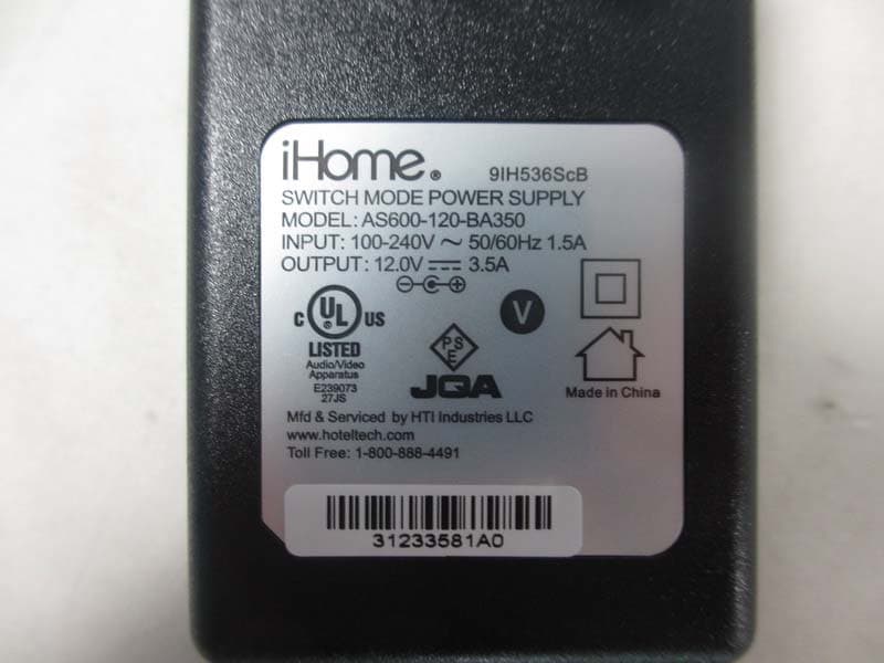
Click to zoom
Application Details
- Equipment Class
- DSS - Part 15 Spread Spectrum Transmitter
- Date of Grant
- Apr 22, 2013
- Application Purpose
- Original Equipment
- Date of Application
- Apr 22, 2013
- Equipment Note
- Hotel Bluetooth Universal Bedside Spesker System
- Frequency Range
- 2402.00000000 - 2480.00000000
- Company
- SDI Technologies Inc.
- Country
- United States
Documents & Files
Document Text
Text extracted from the exhibit documents filed with the FCC. Open a document above to read the original.
Users Manual
HDL50 Sta Quick Start Guide Included • HDL50 system • 100V-240V universal AC adaptor Set Up Connect AC adaptor to DC jack/wall outlet Remove pull tab from Backup Battery Compartment located on bottom of the unit. When Low Battery Icon appears on display, replace backup battery with 1 fresh CR2450 battery. Keep unit connected to power when replacing battery or you will lose settings. Remove thumbscrew and remove back cover to access sta controls Secure the attached Security Tether to a wall or other permanent surface. CAUTION: DO NOT attach to an AC outlet or cause it to become entangled with anything that can create a hazardous situation. -1 +1 auto DST time settime zonetime synchigh low volume level12VDC 35000mA 12V 3.5A outlet The unit ships with the Daylight Saving Time (DST) switch in Auto position, and will automatically adjust when the time changes in March and November. Setting Clock Using Time Sync Daylight Saving Time a) Connect a Lightning-compatible iPhone to the Dock Press the Time Sync Button on the back of the unit to instantly set the time on the HDL50. b NOTE: For the fastest, most accurate time setting, set the clock using Time Sync with a) a docked iPhone OR b) an iPhone connected to the USB port iPhone time is always current because it pings off cell towers; iPad or iPod are only accurate to the last time they were synced to a computer. Make sure the DST switch is in AUTO position. If you do not have an iPhone or if time sync fails, set the clock manually. b) connect any iPhone to the USB port using the USB cable that came with it -1 +1 auto DST time sync a snooze/dimmer function talk endpoweriPod/USB/radio Bluetooth/line-in alarm on/off wake-to FM presets alarm set pairing 1- place your device into “discoverable” mode 2- press and hold“pairing” button on unit for 2 sec 3- if prompted, enter code “0000” 4- your device is now paired. You can answer and end calls by pressing “talk” and “end” to use Bluetooth 1- press “alarm set” button 2- use </> to set desired wake-up time 3- press “alarm set” button again to confirm 4- press “wake-to” button to switch between waking to your iPod, USB dock, radio, or buzzer to use alarm Or Manual Clock Setting Press the Time Set Button Press the Time Set Button Press the or button to set time Press the or button to set year Press the or button to set date Press the or button to tune to a desired station (hold to search for next clear station) time set Press and hold the Time Set Button 2 SECS time set time set Press and hold the Time Set Button 2 SECS 2 SECS time set Press the Time Set Button to con rm Clock Setting time set Beep Beep time set Press the Time Set Button to con rm Beep Beep Setting 12/24 Hour Time Display FM Radio FM Presets To toggle time display between 12 or 24 hours, press alarm set button alarm set Press function Button as needed to cycle to FM mode function iPod/USB/radio Bluetooth/line-in Press FM presets Button to cycle to the preset (P1- P6) you wish to set Press FM presets Button to con rm Follow steps above to set all 6 FM presets Once sta has completed setup, replace security cover on back of unit and tighten thumbscrew. Beep Beep Press the or button to select station to preset FM presets Press and hold FM presets Button to con rm preset number FM presets HDL50 Quick Start Guide - Front Size: 432 x 140 mm Printing Color: Black Mat’l: 100 gsm WF paper Mar. 21, 13. HDL50 Quick Start Guide - Inside Size: 432 x 140 mm Printing Color: Black Mat’l: 100 gsm WF paper Mar. 21, 13. HDL50QSG-031913-A © 2013 HTI Industries, LLC. All rights reserved Printed in China
Users Manual
IMPORTANT SAFETY INSTRUCTIONS When used in the directed manner, this unit has been designed and manufactured to ensure your personal safety. However, improper use can result in potential electrical shock or fire hazards. Please read all safety and operating instructions carefully before installation and use, and keep these instructions handy for future reference. Take special note of all warnings listed in these instructions and on the unit. 1. Water and Moisture – The unit should not be used near water. For example: near a bathtub, washbowl, kitchen sink, laundry tub, swimming pool or in a wet basement. 2. Ventilation – The unit should be situated so that its location or position does not interfere with its proper ventilation. For example, it should not be situated on a bed, sofa, rug or similar surface that may block ventilation openings. Also, it should not be placed in a built-in installation, such as a bookcase or cabinet, which may impede the flow of air through the ventilation openings. 3. Heat – The unit should be situated away from heat sources such as radiators, heat registers, stoves or other appliances (including amplifiers) that produce heat. 4. Power Sources – The unit should be connected to a power supply only of the type described in the operating instructions or as marked on the appliance. 5. Power-Cable Protection – Power supply cables should be routed so that they are not likely to be walked on or pinched by items placed upon or against them. It is always best to have a clear area from where the cable exits the unit to where it is plugged into an AC socket. 6. Cleaning – The unit should be cleaned only as recommended. See the Maintenance section of this manual for cleaning instructions. 7. Objects and Liquid Entry – Care should be taken so that objects do not fall and liquids are not spilled into any openings or vents located on the product. 8. Attachments – Do not use attachments not recommended by the product manufacturer. 9. Lightning and Power Surge Protection – Unplug the unit from the wall socket and disconnect the antenna or cable system during a lightning storm or when it is left unattended and unused for long periods of time. This will prevent damage to the product due to lightning and power-line surges. 10. Overloading – Do not overload wall sockets, extension cords, or integral convenience receptacles as this can result in a risk of fire or electric shock. 11. Damage Requiring Service – The unit should be serviced by qualified service personnel when: A. the power supply cable or plug has been damaged. B. objects have fallen into or liquid has been spilled into the enclosure. C. the unit has been exposed to rain. D. the unit has been dropped or the enclosure damaged. E. the unit exhibits a marked change in performance or does not operate normally. 12. Periods of Nonuse – If the unit is to be left unused for an extended period of time, such as a month or longer, the power cable should be unplugged from the unit to prevent damage or corrosion. 13. Servicing – The user should not attempt to service the unit beyond those methods described in the user’s operating instructions. Service methods not covered in the operating instructions should be referred to qualified service personnel. Hotel Technologies, a division of HTI Industries LLC, (hereafter referred to as Hotel Technologies), warrants this product to be free from defects in workmanship and materials, under normal use and conditions, for a period of 30 days from the date of receipt of the item. Should service be required by reason of any defect or malfunction during the warranty period, Hotel Technologies will repair or, at its discretion, replace this product without charge. This decision is subject to verification of the defect or malfunction upon delivery of this product to the Factory Service Center listed below. Before returning this product for service, please first replace the batteries (if applicable) with fresh ones, as exhausted or defective batteries are the most common cause of problems encountered. If service is still required: 1. Fax a representative at 915.633.1388 with a Return Authorization request including proof of purchase date (i.e., invoice number and date from distributor or HTI) to receive a Return Authorization Number. Issuance of Return Authorization Number is subject to review prior to granting. NO ITEM CAN BE ACCEPTED WITHOUT A RETURN AUTHORIZATION NUMBER. 2. Remove batteries (if applicable) and pack the unit in a well-padded, heavy corrugated box. 3. Send the unit by method agreed to with your representative to the Factory Service Center listed below: Consumer Repair Department Hotel Technologies Inc. 1330 Goodyear Drive El Paso TX 79936-6420 NOTE: Improperly packed items or Items received without an RA # cannot receive credit. NOTE: This warranty is valid only if the product is used for the purpose for which it was designed. It does not cover (i) products which have been damaged by negligence, misuse or accident, or which have been modified or repaired by unauthorized persons; (ii) cracked or broken cabinets, or units damaged by excessive heat; (iii) damage to tape cassettes (if applicable); (iv) the cost of shipping this product to the Factory Service Center and its return to the owner. This warranty is valid only in the United States of America and does not extend to owners of the product subsequent to the original purchaser. Any applicable implied warranties are also limited to 30 days, and Hotel Technologies will not be liable for consequential damages. (Some states do not allow limitations on implied warranties or exclusion of consequential damages, so these restrictions may not apply to you.) This warranty gives you specific legal rights, and you may also have other rights which vary from state to state. LIMITED 30 DAY WARRANTY (valid in contiguous U.S.A. only: not valid in Hawaii or Alaska) If you did not purchase this product directly from Hotel Technologies, please cont…
Text truncated - open the document above for the full version.
External Photos
Neutron Engineering Inc. Project No.: 1303C042 Page 2 of 20 Neutron Engineering Inc. Project No.: 1303C042 Page 3 of 20 Neutron Engineering Inc. Project No.: 1303C042 Page 4 of 20 Neutron Engineering Inc. Project No.: 1303C042 Page 5 of 20
ID Label/Location Info
1 OF 1 2013.2.4 01 (B/E) (Customer) F o r m N O . : S -ENG-0120- 0 2 CONFIDENTIAL UNDER NDA Rating label 460-032534-000V0 460-032534-000V0 HDL50HDL50 PVC Plate Printing : Pantone 428C 0.3±0.05 40 +0.10 -0.05 25± 0.05 3 3 此面黑色,亞光,紋面 絲印內容依照左面文件 此面備3M雙面膠
Internal Photos
Neutron Engineering Inc. Project No.: 1303C042 Page 6 of 20 Neutron Engineering Inc. Project No.: 1303C042 Page 7 of 20 Neutron Engineering Inc. Project No.: 1303C042 Page 8 of 20 Neutron Engineering Inc. Project No.: 1303C042 Page 9 of 20 Neutron Engineering Inc. Project No.: 1303C042 Page 10 of 20 Neutron Engineering Inc. Project No.: 1303C042 Page 11 of 20 Neutron Engineering Inc. Project No.: 1303C042 Page 12 of 20 Neutron Engineering Inc. Project No.: 1303C042 Page 13 of 20 Neutron Engineering Inc. Project No.: 1303C042 Page 14 of 20 Neutron Engineering Inc. Project No.: 1303C042 Page 15 of 20 Neutron Engineering Inc. Project No.: 1303C042 Page 16 of 20 Neutron Engineering Inc. Project No.: 1303C042 Page 17 of 20 Neutron Engineering Inc. Project No.: 1303C042 Page 18 of 20 Neutron Engineering Inc. Project No.: 1303C042 Page 19 of 20 Neutron Engineering Inc. Project No.: 1303C042 Page 20 of 20
Test Report
Neutron Engineering Inc. Report No.: NEI-FICP-1-1303C042 Page 1 of 109 FCC/IC Radio Test Report FCC ID: EMOHDL50 IC: 986B-HDL50 This report concerns (check one) : Original Grant Class II Change Issued Date : Mar. 14, 2013 Project No. : 1303C042 Equipment : Hotel Bluetooth Universal Bedside Speaker System Model Name For FCC HDL50, HDL50X (“X” denote as color of cabinet) Model Name For IC HDL50 Applicant : SDI TECHNOLOGIES INC. Address : 1299 Main Street, Rahway, NJ 07065, U.S.A Manufacturer : SDI TECHNOLOGIES INC. Address : 1299 Main Street, Rahway, NJ 07065, U.S.A Tested by: Neutron Engineering Inc. EMC Laboratory Date of Receipt: Mar. 06, 2013 Date of Test: Mar. 06, 2013 ~ Mar. 13, 2013 Testing Engineer : (David Mao) Technical Manager : (Leo Hung) Authorized Signatory : (Steven Lu) Neutron Engineering Inc. No.3,Jinshagang 1st Road, ShiXia, Dalang Town, Dong Guan, China. TEL : (0769) 8318-3000 FAX : (0769) 8319-6000 Neutron Engineering Inc. Report No.: NEI-FICP-1-1303C042 Page 2 of 109 Declaration Neutron represents to the client that testing is done in accordance with standard procedures as applicable and that test instruments used has been calibrated with the standards traceable to National Measurement Laboratory (NML) of CHINA, or National Institute of Standards and Technology (NIST) of U.S.A. Neutron's reports apply only to the specific samples tested under conditions. It is manufacture’s responsibility to ensure that additional production units of this model are manufactured with the identical electrical and mechanical components. Neutron shall have no liability for any declarations, inferences o r generalizations drawn by the client or others from Neutron issued reports. Neutron’s reports must not be used by the client to claim product endorsement by the authorities or any agency of the Government. This report is the confidential property of the client. As a mutual protection to the clients, the public and Neutron-self, extracts from the test report shall not be reproduced except in full with Neutron’s authorized written approval. Neutron’s laboratory quality assurance procedures are in compliance with the ISO Guide 17025 requirements, and accredited by the conformity assessment authorities listed in this test report. Limitation For the use of the authority's logo is limited unless the Test Standard(s)/Scope(s)/Item(s) mentioned in this test report is (are) included in the conformity assessment authorities acceptance respective. Neutron Engineering Inc. Report No.: NEI-FICP-1-1303C042 Page 3 of 109 Table of Contents Page 1 . CERTIFICATION 5 2 . SUMMARY OF TEST RESULTS 6 2.1 TEST FACILITY 7 2.2 MEASUREMENT UNCERTAINTY 7 3 . GENERAL INFORMATION 8 3.1 GENERAL DESCRIPTION OF EUT 8 3.2 DESCRIPTION OF TEST MODES 10 3.3 TABLE OF PARAMETERS OF TEXT SOFTWARE SETTING 10 3.4 BLOCK DIGRAM SHOWING THE CONFIGURATION OF SYSTEM TESTED 11 3.5 DESCRIPTION OF SUPPORT UNITS 12 4 . EMC EMISSION TEST 13 4.1 CONDUCTED EMISSION MEASUREMENT 13 4.1.1 POWER LINE CONDUCTED EMISSION LIMITS 13 4.1.2 MEASUREMENT INSTRUMENTS LIST AND SETTING 13 4.1.3 TEST PROCEDURE 14 4.1.4 DEVIATION FROM TEST STANDARD 14 4.1.5 TEST SETUP 14 4.1.6 EUT OPERATING CONDITIONS 14 4.1.7 TEST RESULTS 15 4.2 RADIATED EMISSION MEASUREMENT 18 4.2.1 RADIATED EMISSION LIMITS 18 4.2.2 MEASUREMENT INSTRUMENTS LIST ANS SETTING 19 4.2.3 TEST PROCEDURE 20 4.2.4 DEVIATION FROM TEST STANDARD 20 4.2.5 TEST SETUP 21 4.2.6 EUT OPERATING CONDITIONS 22 4.2.7 TEST RESULTS (BELOW 30MHZ) 23 4.2.8 TEST RESULTS (BETWEEN30 – 1000 MHZ) 24 4.2.9 TEST RESULTS (ABOVE 1000 MHZ) 37 5 . NUMBER OF HOPPING CHANNEL 61 5.1 APPLIED PROCEDURES / LIMIT 61 5.1.1 MEASUREMENT INSTRUMENTS LIST AND SETTING 61 5.1.2 TEST PROCEDURE 61 5.1.3 DEVIATION FROM STANDARD 61 5.1.4 TEST SETUP 61 5.1.5 EUT OPERATION CONDITIONS 61 5.1.6 TEST RESULTS 62 6 . AVERAGE TIME OF OCCUPANCY 64 Neutron Engineering Inc. Report No.: NEI-FICP-1-1303C042 Page 4 of 109 Table of Contents Page 6.1 APPLIED PROCEDURES / LIMIT 64 6.1.1 MEASUREMENT INSTRUMENTS LIST 64 6.1.2 TEST PROCEDURE 64 6.1.3 DEVIATION FROM STANDARD 64 6.1.4 TEST SETUP 65 6.1.5 EUT OPERATION CONDITIONS 65 6.1.6 TEST RESULTS 66 7 . HOPPING CHANNEL SEPARATION MEASUREMENT 78 7.1 APPLIED PROCEDURES / LIMIT 78 7.1.1 MEASUREMENT INSTRUMENTS LIST AND SETTING 78 7.1.2 TEST PROCEDURE 78 7.1.3 DEVIATION FROM STANDARD 78 7.1.4 TEST SETUP 78 7.1.5 EUT OPERATION CONDITIONS 78 7.1.6 TEST RESULTS 79 8 . BANDWIDTH TEST 83 8.1 APPLIED PROCEDURES / LIMIT 83 8.1.1 MEASUREMENT INSTRUMENTS LIST AND SETTING 83 8.1.2 TEST PROCEDURE 83 8.1.3 DEVIATION FROM STANDARD 83 8.1.4 TEST SETUP 83 8.1.5 EUT OPERATION CONDITIONS 83 8.1.6 TEST RESULTS 84 9 . PEAK OUTPUT POWER TEST 88 9.1 APPLIED PROCEDURES / LIMIT 88 9.1.1 MEASUREMENT INSTRUMENTS LIST AND SETTING 88 9.1.2 TEST PROCEDURE 88 9.1.3 DEVIATION FROM STANDARD 88 9.1.4 TEST SETUP 88 9.1.5 EUT OPERATION CONDITIONS 88 9.1.6 TEST RESULTS 89 10 . ANTENNA CONDUCTED SPURIOUS EMISSION 93 10.1 APPLIED PROCEDURES / LIMIT 93 10.1.1 MEASUREMENT INSTRUMENTS LIST AND SETTING 93 10.1.2 TEST PROCEDURE 93 10.1.3 DEVIATION FROM STANDARD 93 10.1.4 TEST SETUP 93 10.1.5 EUT OPERATION CONDITIONS 93 10.1.6 TEST RESULTS 94 11 . EUT TEST PHOTO 106 Neutron Engineering Inc. Report No.: NEI-FICP-1-1303C042 Page 5 of 109 1. CERTIFICATION Equipment : Hotel Bluetooth Universal Bedside Speaker System Brand Name : iHome Model Name For FCC HDL50, HDL50X (“X” denote as color of cabinet) Model Name For IC HDL50 Applicant : SDI TECHNOLOGIES INC. Factory : Shenzhen Synchron Electronics Co., Ltd. Address : No. 9 Mei Li Road, Xia Mei Lin, Fu Tian Area, Shenzhen, Guangdong, China Date of Test : Mar. 06, 2013 ~ Mar. 13, 2013 Test Item : ENGINEERING SAMPLE Standards : FCC Part15, Subpart C(15.247) / ANSI C63.4 : 2009 FCC Public Notice DA 00-705, March 30, 2000. Canada RSS-210:2010 RSS-GEN Issue 3, Dec 2010 The above equipment has been tested and found compliance with the requirement of the relative standards by Neutron Engineering Inc. EMC Laboratory. The t…
Text truncated - open the document above for the full version.
Test Setup Photos
Neutron Engineering Inc. Report No.: NEI-FICP-1-1303C042 Page 106 of 109 11. EUT TEST PHOTO Conducted Measurement Photos Neutron Engineering Inc. Report No.: NEI-FICP-1-1303C042 Page 107 of 109 Radiated Measurement Photos 9K~30MHz Neutron Engineering Inc. Report No.: NEI-FICP-1-1303C042 Page 108 of 109 Radiated Measurement Photos 30M~1000MHz Neutron Engineering Inc. Report No.: NEI-FICP-1-1303C042 Page 109 of 109 Radiated Measurement Photos Above 1000MHz
Contact Information
Applicant
David Stetin(Compliance Officer)
Test Firm
BTL Inc.Daisy Dai
Technical Specifications
| # | Rule Parts | Frequency Range | Power Output |
|---|---|---|---|
| 1 | 15C | 2.40 GHz - 2.48 GHz | 1.20 mW |
Other Applications from SDI Technologies Inc.
EMOIPCV3A
May 27, 2026Magnetic Wallet Power Bank
Equipment Class
DCD - Part 15 Low Power Transmitter Below 1705 kHz
EMOTW502A
Apr 22, 2026ALARM CLOCK WITH NIGHTLIGHT AND FAST WIRELESS CHARGING
Equipment Class
DCD - Part 15 Low Power Transmitter Below 1705 kHz
EMO555B
Nov 23, 2025Bluetooth Karaoke
Equipment Class
DSS - Part 15 Spread Spectrum Transmitter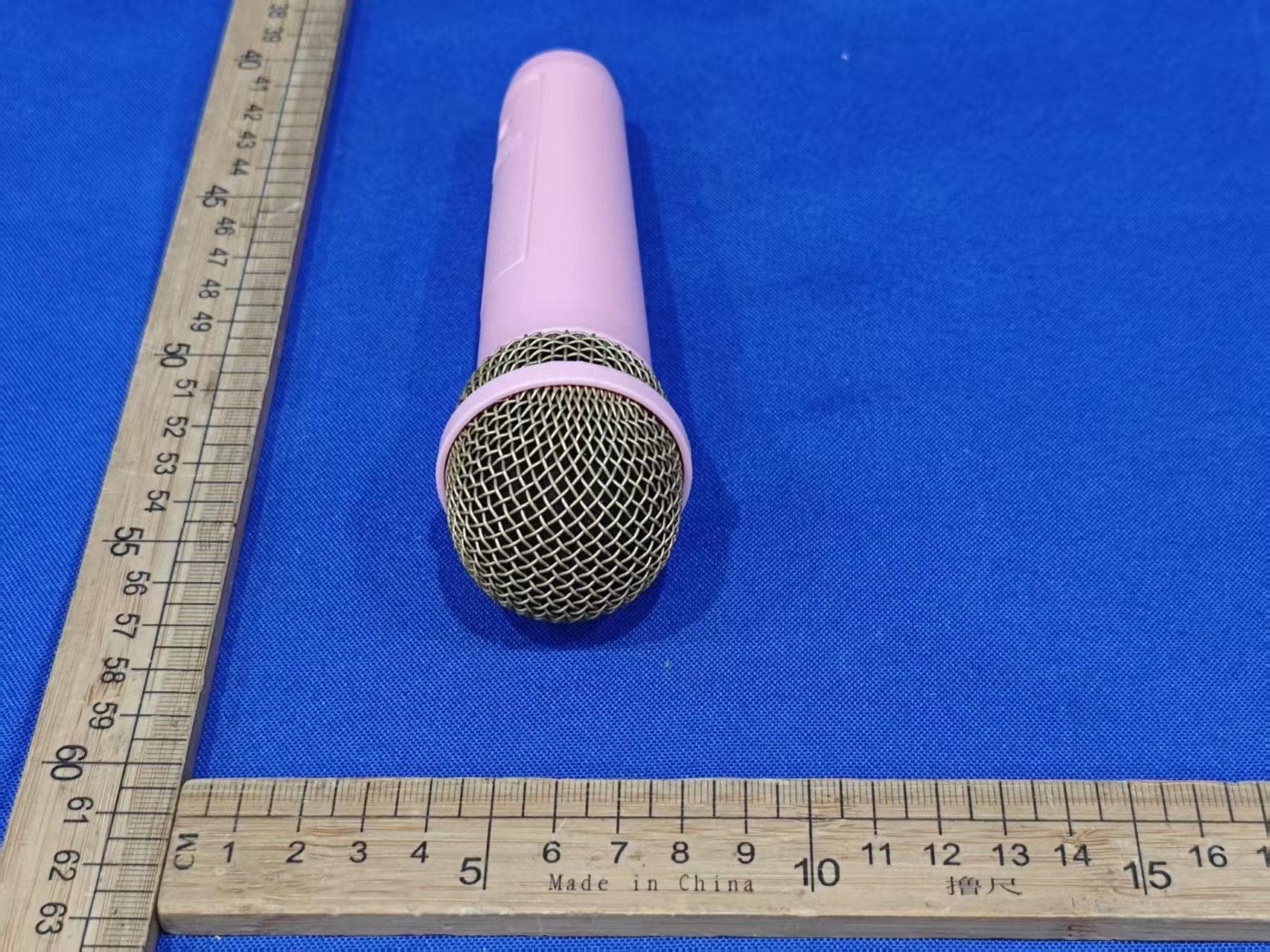
EMO555BM
Nov 23, 2025Bluetooth Karaoke
Equipment Class
DTS - Digital Transmission System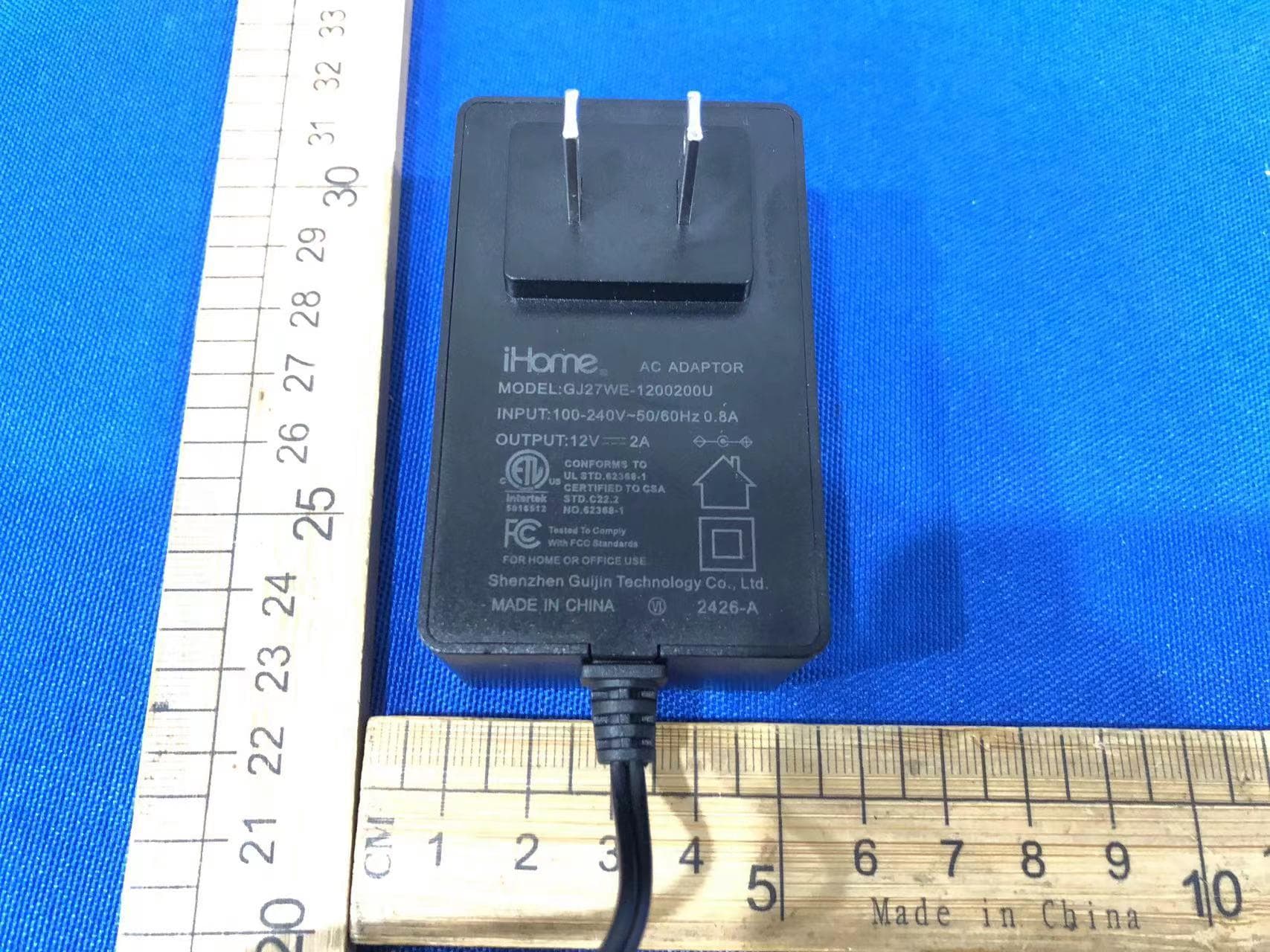
EMOIBTW112A
Sep 07, 2024Bluetooth Alarm Clock with wireless and USB charging
Equipment Class
DSS - Part 15 Spread Spectrum Transmitter