EMOHW5BWireless Qi Charging Bedside Clock Stereo Speaker with Single Day Alarm and Dual USB Charging
SDI Technologies Inc.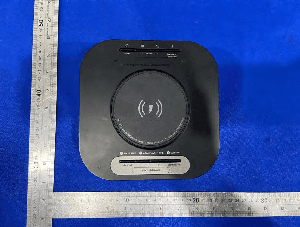
Click to zoom
Application Details
- Equipment Class
- DCD - Part 15 Low Power Transmitter Below 1705 kHz
- Date of Grant
- Aug 01, 2021
- Application Purpose
- Original Equipment
- Date of Application
- Aug 01, 2021
- Equipment Note
- Wireless Qi Charging Bedside Clock Stereo Speaker with Single Day Alarm and Dual USB Charging
- Frequency Range
- 0.11000000 - 0.20500000
- Company
- SDI Technologies Inc.
- Country
- United States
Documents & Files
Document Text
Text extracted from the exhibit documents filed with the FCC. Open a document above to read the original.
Users Manual
HW5 Sta Quick Start Guide Included • HW5 system • Universal AC adaptor Set Up Daylight Saving Time HW5QSG-060921-F© 2021 HTI Industries, LLC. All rights reservedPrinted in China Setting the Time Zone and Clock (Factory Preset Clock) Connect the universal voltage AC adaptor to the DC jack on the bottom panel of the unit. Plug into a wall outlet that is not controlled by a light switch and is within easy reach of the unit. The unit ships with the Daylight Saving Time (DST) switch located on the bottom of the unit in Auto position, and will automatically adjust when the time changes in March and November. To switch manually, slide switch to +1 to add an hour or to -1 to subtract an hour. The first time you connect your new preset clock to the AC outlet, the unit will automatically show the correct Eastern Standard time, which is the default setting. If you are not in the Eastern time zone, you must change the default setting to match your time zone (see Time Zone Setting below). Once the correct time zone is set, if the time displayed is not correct, follow steps under Manual Clock Setting to set the correct hour, minute, year and date. Press and release the – or + button as needed until your time zone is displayed. The time display will also change according to zone selected. When Low Battery Icon flashes on the bottom right of the display, replace backup batteries with 2 fresh AA batteries. Keep unit connected to AC power when replacing batteries or you will lose settings. Make sure to match polarity (+/–) on batteries as shown below. Battery Cautions and Tips •Only use the recommended/supplied batteries or equivalent. • Use alkaline batteries for longer life. • Do not mix old and new batteries, and do not mix alkaline, carbon-zinc or rechargeable nickel-cadmium batteries. •Insert batteries with proper polarity (+/–) as indicated. • Remove exhausted batteries from product. • Do not attempt to recharge non-rechargeable batteries. • Do not open batteries or heat them beyond normal ambient temperatures. • To prevent battery leakage or damage, remove batteries from a pr oduct if it will not be used f or a month or longer. • Use extreme caution handling leaking batteries (avoid direct contact with eyes and skin). If battery leakage comes in contact with eyes, IMMEDIATELY flush the eye with lukewarm and gently flowing water for at least 30 minutes. If skin contact occurs, wash skin with clear water for at least 15 minutes. Seek medical attention if any symptoms occur. • Store in cool, dry, ventilated area away from hazardous or combustible material. • Do not dispose of batteries in the household trash or fire. • Follow applicable laws and local regulations for the disposal and transporta tion of ba tteries. •Caution – Risk of explosion if the battery is replaced by an incorrect type. Time Zone Setting Battery backup installation Volume Limiter The unit ships with the Volume Limit switch in HI position, and the maximum volume output will be at 100%. For smaller rooms, slide the switch to the LO position to limit/lower the maximum volume by 25%. Press and hold the time zone button located on the bottom of the unit. The default EASTERN time zone will flash in the bottom of the display. Press and release the time zone button to confirm time zone setting. outlet Low Battery Icon AA x 2 Bluetooth is a registered trademarks of Bluetooth SIG Inc. Bluetooth technology is incorporated under license from Bluetooth SIG Inc. Press the time set button to confirm year. The date will flash. Press the – or + button to set the date (hold for rapid adjust). Press the time set button. 2 beeps will confirm Clock Setting is complete. √ TIP: Press the Alarm On/O Button when display is flashing during clock setting to toggle between 12 hour and 24 hour display modes. Note: Make sure that the Year, Month, and Date settings are correct so that the Auto Daylight Savings Time adjustments will occur on time. • Place the unit on a level surface away from sources of direct sunlight or excessive heat. • Remove plastic protective film from the clock display. • Clean your unit with a soft, damp cloth. Strong cleaning agents, such as thinner or similar materials can damage the surface of the unit. Secure the attached Security Tether to a wall or other permanent surface. CAUTION: DO NOT attach to an AC outlet or cause it to become entangled with anything that can create a hazardous situation. Tips For Guests •Using the wireless charger: Place Qi compatible device in the middle of marked charging target circle, with the front facing you. Check the wireless charging icon on the right of the display: •Rapid blinking icon – Device is not charging. Reposition device. •Slow blinking icon – Device is charging properly. •Solid icon – Device is charged (some devices do not support this feature). •No icon – Not in charging mode (no device on unit) Note: • Thick or metal device cases can interfere with wireless charging. Removing such a case may improve wireless charging. • Wireless charging uses a magnetic field. Avoid placing any metal object or personal items with magnetic stripes (credit cards, bank cards, key cards, metal or magnetic phone cases) near the wireless charging area to prevent damage. • This unit is compatible with the Qi wireless charging standard. PMA wireless charging is not supported. The wireless charging process generates heat that may cause phones and chargers to get warm to the touch. This is natural for wireless charging devices. USB Charging (Unit Includes USB-C Port and Standard USB Port) FCC Radiation Exposure Statement This equipment complies with FCC RF radiation exposure limits set forth for an uncontrolled environment. This equipment should be installed and operated with minimum distance 20cm between the radiator & your body. • Warning: Changes or modifications to this unit not expressly approved by the party responsible for compliance could void the user’s authority to operate the equipment. • NOTE: This …
Text truncated - open the document above for the full version.
Cover Letter(s)
Rev11/20/07 SDITechnologiesInc. FederalCommunicationsCommission AuthorizationandEvaluationDivision ConfidentialityRequestregardingapplicationforcertificationofFCCID:EMOHW5B PursuanttoSections0.457and0.459oftheCommission’sRules,weherebyrequestconfidential treatmentofinformationaccompanyingthisapplicationasoutlinedbelow: ExhibitTypeFileName BlockDiagram Schematics OperationalDescription BlockDiagram Schematics OperationalDescription Theabovematerialscontaintradesecretsandproprietaryinformationnotcustomarilyreleasedto thepublic.Thepublicdisclosureofthesematerialsmaybeharmfultotheapplicantandprovide unjustifiedbenefitstoitscompetitors. TheapplicantunderstandsthatpursuanttoSection0.457oftheRules,disclosureofthis applicationandallaccompanyingdocumentationwillnotbemadebeforethedateoftheGrant forthisapplication. PursuanttoDA04-1705June15,2004oftheCommission’spublicnotice,Wealsorequestingthe commissiontograntshort-termconfidentialityrequestonthefollowingattachmentsuntil180 daysaftertheGrantDateofEquipmentAuthorizations. ExhibitTypeFileName ManualUsermanual Sincerely, DavidStetin 2021-08-02
Cover Letter(s)
SDITechnologiesInc. Declarationonmodeldifference Wetheundersignedherebyconfirmthatthesemodelsareidentical,andallmodelshavethe sameRFmoduleandantenna,PCBlayout,schematicsandcomponent.Onlydifferentonmodel numberandcolorofappearance. ProductionnameTrademarkFCCModelno. WirelessQiCharging BedsideClockStereo SpeakerwithSingleDay AlarmandDualUSB Charging iHomeEMOHW5B HW5,HW5B,HW5X ( Xcouldbe singleormultipledigitsbyany alphabetsdenotedifferent cabinetcolor ) Confirmedby: DavidStetin 2021-08-02
Cover Letter(s)
W:\案件资料\案件数据图片\罗工\ED191107034EKIDiBT235FCCIDReport\work\POA_Letter_140225.docx SDITechnologiesInc. FederalCommunicationsCommission AuthorizationandEvaluationDivision 1435OaklandMillsRoad Columbia,MD21046 Date:2021-07-06 SUBJECT:FCCApplicationfor(FCCID:EMOHW5B) ToWhomItMayConcern: We,theundersigned,herebyauthorizeEMTEK(DONGGUAN)CO.,LTD.atSamLv onourbehalf,toapplytotheFederalCommunicationsCommissiononourequipment. AnyandallactscarriedoutbyEMTEK(DONGGUAN)CO.,LTD.onourbehalfshall havethesameeffectasactsofourown. ThisistoadvisethatweareinfullcompliancewiththeAnti-DrugAbuseAct.We,the applicant,arenotsubjecttoadenialoffederalbenefitspursuanttoSection5301ofthe Anti-DrugActof1988,21USC853a,andnopartytotheapplicationissubjecttoadenial offederalbenefitspursuanttothatsection. Regards, Sincerely, DavidStetin 2021-08-02
ID Label/Location Info
USBUSB-C D o n o t p l a c e m e t a l p h o n e c a s e s o r m e t a l o b j e c t s i n t h e w i r e l e s s c h a r g i n g a r e a . START HERECONFIRMADJUST ALARM TIME VIEWING AREA 20MM X 72.5MM snooze | dimmer alarm setalarm on-o bluetooth press + hold powervolume Title: Wireless Qi Charging Bedside Clock Stereo Speaker w/ Single Day Alarm + Dual USB Charging Version: 9 Designer: Eric Holzer Date: 02. 19. 2020 Model #: HW5 GAW revised May 24, 2021 revised May 24, 2021: BK3266 new PCB version Clock Backup: DC 3V, AA x 2 Input: DC 12V, 5A HW5-A-BService Number: Made in China Serviced by Hotel Technologies, Inc. Patent Pending CAN RSS-216 / CNR-216 FCC ID: EMOHW5B IC: 986B-HW5B HVIN: HW5b MODEL: DST -1 +1 AUTO TIME ADJUST TIME SETTIME ZONE VOL LIMITER HI LOW actual size: 72.2W x 28.8H (mm) www.hoteltech.com Wireless Charger Supports Samsung 9W Fast Charge USB output : 5V 2.4A (12W) USBC output : 5V 3A , 9V 2A (18W) HKCS: 05/24/2021-V15 Mar 1, 2021 running change start for PO# 4420000324-3K
Internal Photos
Coil ANT BTANT
RF Exposure Info
TRFNO.FCC15C/APage1of10 AccesstotheWorld 1.EUTSPECIFICATION FCCID:EMOIW18B CharacteristicsDescription ProductName WirelessQiChargingBedsideClockStereoSpeakerwith SingleDayAlarmandDualUSBCharging Modelnumber HW5,HW5B,HW5X ( Xcouldbesingleormultipledigitsby anyalphabetsdenotedifferentcabinetcolor) PowerSupplyAC120V OperatingFrequency Range 110KHz-205KHz Modulation Technique ASK AntennaTypeInductionCoilantenna DevicecategoryPortable(<20cmseparation) Mobile(>20cmseparation) Others___ Exposure classification Occupational/Controlledexposure(S=5mW/cm2) GeneralPopulation/Uncontrolledexposure (S=1mW/cm2) AntennadiversitySingleantenna Multipleantennas Txdiversity Rxdiversity Tx/Rxdiversity EvaluationappliedMPEEvaluation SAREvaluation TRFNO.FCC15C/APage2of10 AccesstotheWorld 2.SUMMARYOFTESTRESULT EMISSION DescriptionofTestItemStandard&LimitsResults MPE FCCPart1(1.1310)andPart2(2.1091) 680106D01RFExposureWireless ChargingAppv03 Pass Note:N/AisanabbreviationforNotApplicable. TRFNO.FCC15C/APage3of10 AccesstotheWorld 3.MEASURINGDEVICEANDTESTEQUIPMENT 3.1.ForMPEMeasurement UsedEquipmentManufacturerModelNo.SerialNo.LastCal.Cal.Interval Probe(100cm 2 )NardaELT-400C-0012May22,20211Year E-Field Probe(100kHz-3GHz) NardaEF03912304/03May22,20211Year BroadbandFieldMeterNardaNBM-550232421May22,20211Year ExposureLevel Tester(1Hz-400KHz) NardaELT-400C-0012May22,20211Year TRFNO.FCC15C/APage4of10 AccesstotheWorld 4.RFEXPOSURE 4.1.MeasuringStandard FCCPart1(1.1310)andPart2(2.1091) 4.2.Requiments ThreedifferentcategoriesoftransmittersaredefinedbytheFCCinOETBulletin65.Thesecategories arefixedinstallation,mobile,andportableandaredefinedasfollows:oFixedInstallations:fixed locationmeansthatthedevice,includingitsantenna,isphysicallysecuredatapermanentlocationand isnotabletobeeasilymovedtoanotherlocation.Additionally,distancetohumansfromtheantennais maintainedtoatleast2meters.oMobileDevices:amobiledeviceisdefinedasatransmittingdevice designedtobeusedinotherthanfixedlocationsandtobegenerallyusedinsuchawaythata separationdistanceofatleast20centimetersisnormallymaintainedbetweenthetransmitter'sradiating structuresandthebodyoftheuserornearbypersons.Transmittersdesignedtobeusedbyconsumers orworkersthatcanbeeasilyre-located,suchasawirelessmodemoperatinginalaptopcomputer,are consideredmobiledevicesiftheymeetthe20centimeterseparationrequirement.TheFCCrulesfor evaluatingmobiledevicesforRFcompliancearefoundin47CFR§2.1091.oPortableDevices:a portabledeviceisdefinedasatransmittingdevicedesignedtobeusedsothattheradiatingstructure(s) ofthedeviceis/arewithin20centimetersofthebodyoftheuser.Portabledevicerequirementsare foundinSection2.1093oftheFCC'sRules(47CFR§2.1093).TheFCCalsocategorizestheuseof thedeviceasbasedupontheuser’sawarenessandabilitytoexercisecontroloverhisorherexposure. ThetwocategoriesdefinedareOccupational/ControlledExposureandGeneral Population/UncontrolledExposure.Thesetwocategoriesaredefinedasfollows: Occupational/ControlledExposure:Ingeneral,occupational/controlledexposurelimitsareapplicableto situationsinwhichpersonsareexposedasaconsequenceoftheiremployment,whohavebeenmade fullyawareofthepotentialforexposureandcanexercisecontrolovertheirexposure.Thisexposure categoryisalsoapplicablewhentheexposureisofatransientnatureduetoincidentalpassagethrough alocationwheretheexposurelevelsmaybehigherthanthegeneralpopulation/uncontrolledlimits,but theexposedpersonisfullyawareofthepotentialforexposureandcanexercisecontroloverhisorher exposurebyleavingtheareaorbysomeotherappropriatemeans.AwarenessofthepotentialforRF exposureinaworkplaceorsimilarenvironmentcanbeprovidedthroughspecifictrainingaspartofaRF safetyprogram.Ifappropriate,warningsignsandlabelscanalsobeusedtoestablishsuchawareness byprovidingprominentinformationontheriskofpotentialexposureandinstructionsonmethodsto minimizesuchexposurerisks.GeneralPopulation/UncontrolledExposure:Thegeneralpopulation/ uncontrolledexposurelimitsareapplicabletosituationsinwhichthegeneralpublicmaybeexposedor inwhichpersonswhoareexposedasaconsequenceoftheiremploymentmaynotbemadefullyaware ofthepotentialforexposureorcannotexercisecontrolovertheirexposure.Membersofthegeneral publicwouldcomeunderthiscategorywhenexposureisnotemployment-related;forexample,inthe caseofawirelesstransmitterthatexposespersonsinitsvicinity.Warninglabelsplacedonlow-power consumerdevicessuchascellulartelephonesarenotconsideredsufficienttoallowthedevicetobe consideredundertheoccupational/controlledcategory,andthegeneralpopulation/uncontrolled exposurelimitsapplytothesedevices. TRFNO.FCC15C/APage5of10 AccesstotheWorld 4.3.Testconfiguration 1)ThefieldstrengthofbothE-fieldandH-fieldwasmeasuredat15cm(the15cmmeasuredfromthe centeroftheprobe(s)totheedgeofthedevice)usingtheequipmentlistabovefordetermining compliancewiththeMPErequirementsofFCCPart1.1310. 2)TheRFpowerdensitywasmeasuredat3ifferentchargeconditions:.minload,midload,maxload. 3)MaximumE-fieldandH-fieldmeasurementsweremade15cmfromeachsideoftheEUT.Alongthe sideoftheEUTandstill15cmawayfromtheedgeoftheEUT,thefieldprobeswerepositionedatthe locationwherethereismaximumfieldstrength.ThemaximumE-fieldandH-fieldisreportedbelow. 4)Emissionsbetween100kHzto300kHzshouldbeassessedversusthelimitsat300kHzinTable1of Section1.1310:614V/mand1.63A/m.AKDBinquiryisrequiredtodeterminetheapplicable exposurelimitsbelow100kHz. 5)Thisdeviceusesawirelesschargingcircuitforpowertransferoperatingatthefrequencyof 110KHz-208KHz.Thus,thelimitswereused:E-fieldLimit=614(V/m);H-fieldlimit=1.63(A/m). TRFNO.FCC15C/APage6of10 AccesstotheWorld 4.4.Limits TestModeDescriptionRemark ModeA Charging 100%LoadWithresistor 50%LoadWithresistor 0%LoadNoload TRFNO.FCC15C/APage7of10 AccesstotheWorld 4.5.MeasuringResults TestMode:ModeA.1(100%Load) ElectricFieldEmissions TestPositionMeasureValue(V/m)Limit(V/m) Top2.14 614 Left2.82 614 Right2.94 614 Rear2.79 614 Front3.18 614 Bottom1.95 614 MagneticFieldEmissions TestPositionMeasureValue(A/m)Limit(A/m) Top0.0265 1.63 Left0.0329 1.63 Right0.0357 1.63 Rear0.0338 1.63 Front0.057…
Text truncated - open the document above for the full version.
Test Report
Report No. EDG2107060069E00202RPage 1 of 22 Ver.1.0 TEST REPORT Product Name : Wireless Qi Charging Bedside Clock Stereo Speaker with Single Day Alarm and Dual USB Charging Model Number :HW5, HW5B, HW5X(X could be single or multiple digits by any alphabets denote different cabinet color) FCC ID : EMOHW5B Prepared for:SDI Technologies Inc. Address:1299 Main Street, Rahway, NJ 07065, U.S.A Prepared by:EMTEK (DONGGUAN) CO., LTD. Address:-1&2/F.,Building 2, Zone A, Zhongda Marine Biotechnology Reserch and Development Base, No.9, Xincheng Avenue, Songshanhu High-technology Industrial Development Zone, Dongguan, Guangdong, China TEL: +86-0769-22807078 FAX: +86-0769-22807079 Report Number:EDG2107060069E00202R Date(s) of Tests:July 08, 2021 to July 23, 2021 Date of issue:July 23, 2021 $二维码$ Report No. EDG2107060069E00202RPage 2 of 22 Ver.1.0 TABLE OF CONTENT Test Report DescriptionPage 1. SUMMARY OF TEST RESULTS.......................................................................................................................................5 2. GENERAL INFORMATION ................................................................................................................................................ 6 2.1. Description of Device (EUT).......................................................................................................................................6 2.2. Input / Output Ports......................................................................................................................................................6 2.3. Independent Operation Modes...................................................................................................................................7 2.4. Test Manner ................................................................................................................................................................... 7 2.5. Description of Test Facility ........................................................................................................................................... 7 2.6. Test Software ................................................................................................................................................................. 7 2.7. Description of Support Device....................................................................................................................................8 2.8. Measurement Uncertainty...........................................................................................................................................8 3. MEASURING DEVICE AND TEST EQUIPMENT..........................................................................................................9 3.1. Conducted Emission Test Equipment ........................................................................................................................ 9 3.2. For 3m Radiated Emission Measurement 9K-30M (3m chamber 1#) .................................................................. 9 3.3. For 3m Radiated Emission Measurement 30M-1G (3m chamber 1#) .............................................................. 9 4. 20DB BANDWIDTH..........................................................................................................................................................10 4.1. Test Procedure............................................................................................................................................................10 4.2. Test Results.................................................................................................................................................................10 5. POWER LINE CONDUCTED EMISSION MEASUREMENT ..................................................................................... 11 5.1. Block Diagram of Test Setup ..................................................................................................................................... 11 5.2. Limits ............................................................................................................................................................................. 11 5.3. Test Procedure............................................................................................................................................................11 5.4. Measuring Results......................................................................................................................................................12 6. RADIATED EMISSION TEST..........................................................................................................................................15 6.1. Measurement Procedure ........................................................................................................................................... 15 6.2. Test SET-UP (Block Diagram of Configuration) ..................................................................................................... 15 6.3. Measurement Equipment Used ................................................................................................................................ 16 6.4. Radiated Emission Limit............................................................................................................................................16 6.5. Measurement Result..................................................................................................................................................18 7. ANTENNA REQUIREMENT............................................................................................................................................21 Report No. EDG2107060069E00202RPage 3 of 22 Ver.1.0 TEST REPORT DESCRIPTION Applicant:SDI Technologies Inc. Address:1299 Main Street, Rahway, NJ 07065, U.S.A Manufacturer:Hotel Technologies Inc. Address:1299 Main Street, Rahway, NJ 07065, U.S.A EUT: Wireless Qi Charging B…
Text truncated - open the document above for the full version.
Contact Information
Applicant
David Stetin(Compliance Officer)
Test Firm
EMTEK (Dongguan) Co., Ltd.Sam Lv
[email protected]886-0769-22807078
Technical Specifications
| # | Rule Parts | Frequency Range | Power Output |
|---|---|---|---|
| 1 | 15C | 0.11 MHz - 0.205 MHz | - |
Other Applications from SDI Technologies Inc.
EMOIPCV3A
May 27, 2026Magnetic Wallet Power Bank
Equipment Class
DCD - Part 15 Low Power Transmitter Below 1705 kHz
EMOTW502A
Apr 22, 2026ALARM CLOCK WITH NIGHTLIGHT AND FAST WIRELESS CHARGING
Equipment Class
DCD - Part 15 Low Power Transmitter Below 1705 kHz
EMO555B
Nov 23, 2025Bluetooth Karaoke
Equipment Class
DSS - Part 15 Spread Spectrum Transmitter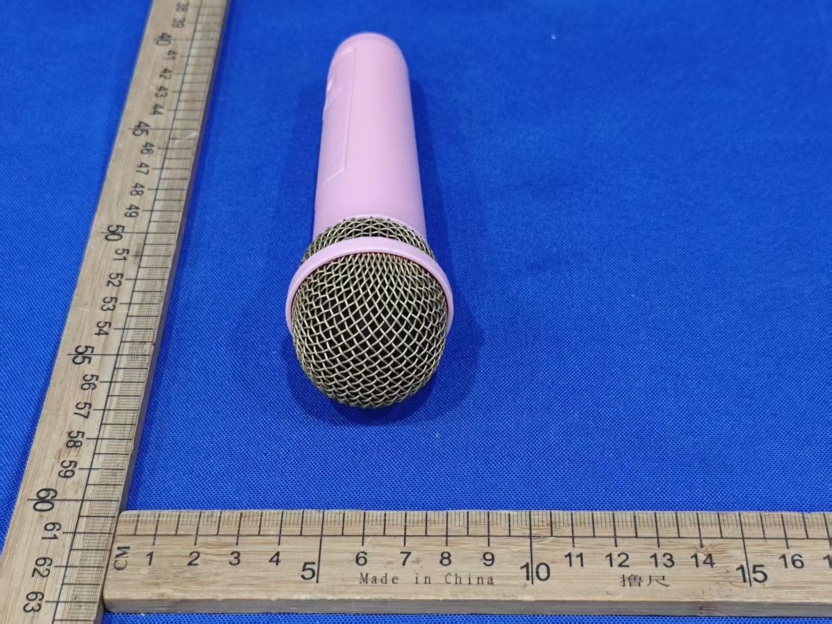
EMO555BM
Nov 23, 2025Bluetooth Karaoke
Equipment Class
DTS - Digital Transmission System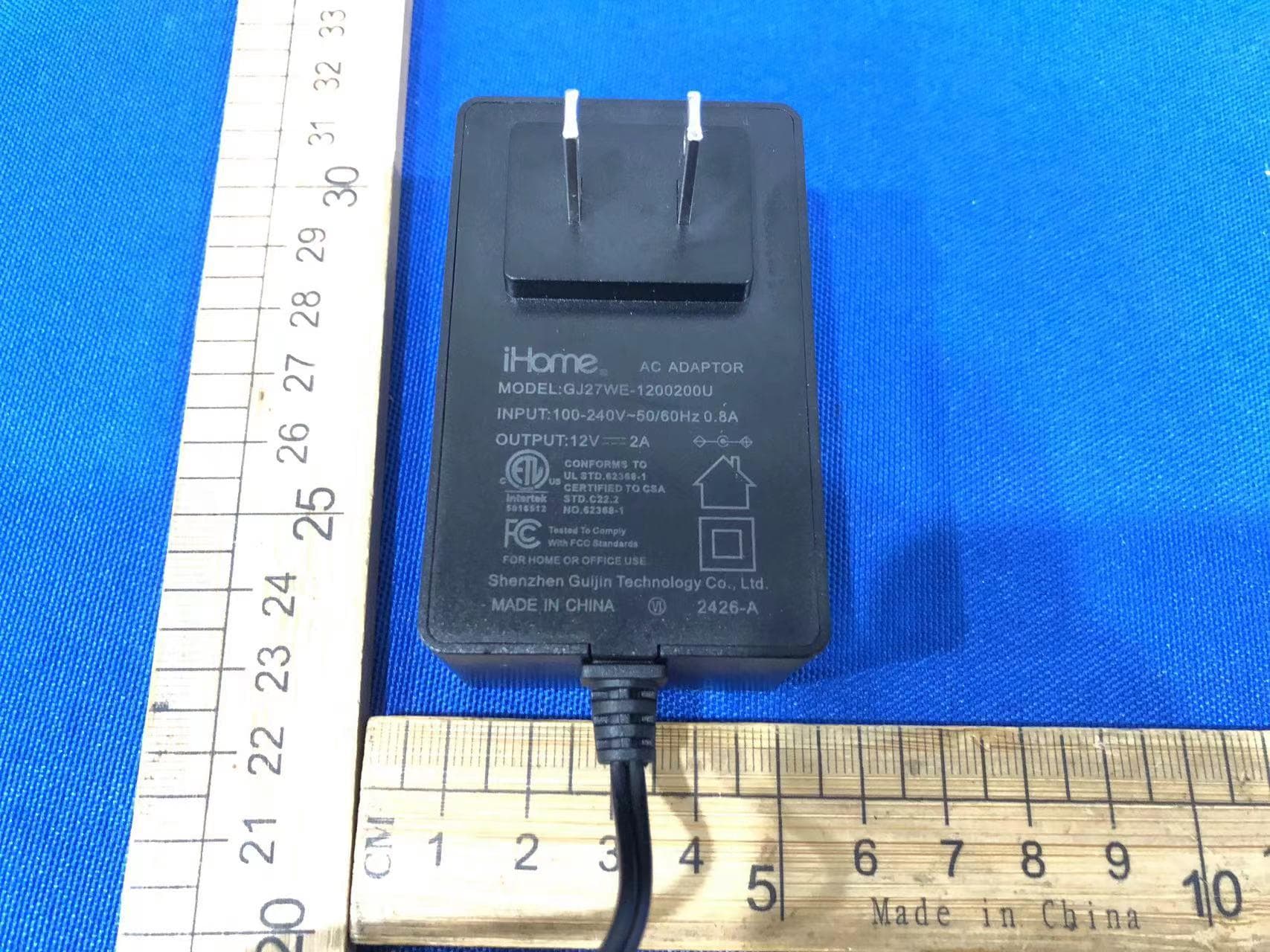
EMOIBTW112A
Sep 07, 2024Bluetooth Alarm Clock with wireless and USB charging
Equipment Class
DSS - Part 15 Spread Spectrum Transmitter